

Page 1
GF Piping Systems
Bedienungsanleitung
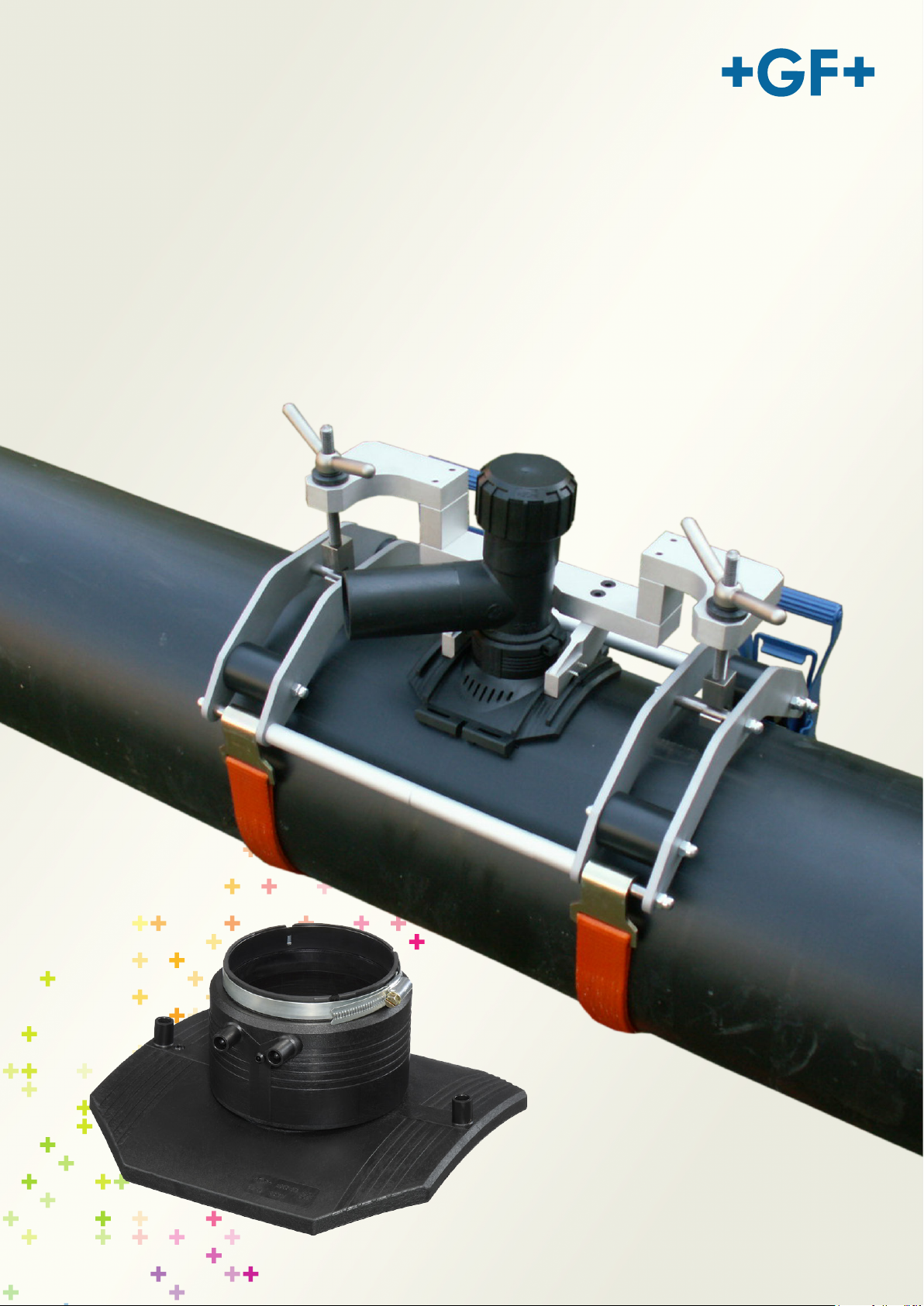
Spannvorrichtung
Topload 400 Code 799.350.475
Topload 630 Code 799.350.477
Page 2

Alle Rechte, insbesondere das Recht der Vervielfältigung und Verbreitung sowie der Übersetzung,
vorbehalten. Vervielfältigungen oder Reproduktionen in jeglicher Form (Druck, Fotokopie, Mikrofilm oder
Datenerfassung) bedürfen der schriftlichen Genehmigung durch die Georg Fischer Piping Systems.
Page 3

Bedienungsanleitung Spannvorrichtung Topload Inhaltsverzeichnis
0
1
1
2
1
3
3
3
2
4
4
4
5
5
3
6
6
7
10
13
4
13
13
5
14
Inhaltsverzeichnis
Seite
Zu dieser Anleitung
0.1 Warnhinweise
0.2 Weitere Symbole und Auszeichnungen
Sicherheitshinweise
1.1 Bestimmungsgemässe Verwendung
1.2 Sicherheitsvorschriften
Aufbau des Produkts
2.1 Topload 400
2.2 Technische Daten Topload 400
2.3 Topload 630
2.4 Technische Daten Topload 630
Vorbereitung und Montage
3.1 Vorbereitung
3.2 Montage Topload 400
3.3 Montage Topload 630
3.4 Demontieren
Wartung
4.1 Service/Kundendienst
Ersatzteile
I
Page 4
Inhaltsverzeichnis Bedienungsanleitung Spannvorrichtung Topload
II
Page 5
Bedienungsanleitung Spannvorrichtung Topload 0 Zu dieser Anleitung
Warnsymbol
Bedeutung
0 Zu dieser Anleitung
Für das schnelle Erfassen dieser Anleitung und das sichere Umgehen mit der
Maschine werden Ihnen hier die in der Anleitung verwendeten Warnhinweise,
Hinweise und Symbole sowie deren Bedeutung vorgestellt.
0.1 Warnhinweise
In dieser Anleitung werden Warnhinweise verwendet, um Sie vor Verletzungen
oder vor Sachschäden zu warnen. Lesen und beachten Sie diese
Warnhinweise immer!
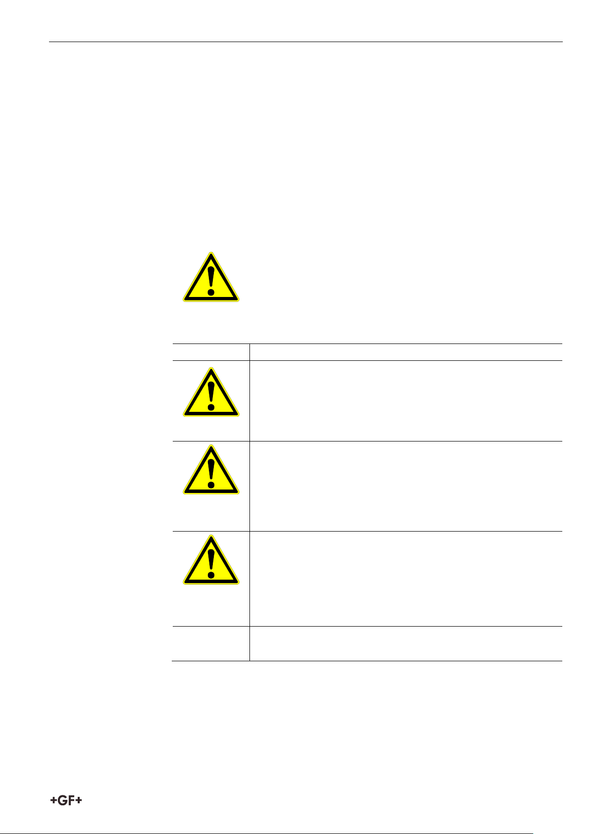
Dies ist das Warnsymbol. Es warnt Sie vor Verletzungsgefahren.
Befolgen Sie alle Maßnahmen, die mit dem Sicherheitszeichen
gekennzeichnet sind, um Verletzungen oder Tod zu
vermeiden.
GEFAHR
WARNUNG
VORSICHT
VORSICHT
Unmittelbar drohende Gefahr!
Bei Nichtbeachtung drohen Ihnen Tod oder schwerste
Verletzungen.
Verbote (wenn vorhanden).
Massnahmen, um die Gefahr zu vermeiden.
Möglicherweise drohende Gefahr!
Bei Nichtbeachtung drohen Ihnen schwere Verletzungen.
Verbote (wenn vorhanden).
Massnahmen, um die Gefahr zu vermeiden.
Gefährliche Situation!
Bei Nichtbeachtung drohen leichte Verletzungen.
Gefährliche Situation!
Bei Nichtbeachtung drohen Sachschäden.
1
Page 6
0 Zu dieser Anleitung Bedienungsanleitung Spannvorrichtung Topload
Symbol
Bedeutung
Allein stehende Handlungsaufforderung: Hier müssen Sie
0.2 Weitere Symbole und Auszeichnungen
Wichtig
Hinweis
1.
Hinweise: Enthalten besonders wichtige Informationen zum
Verständnis.
Handlungsaufforderung in einer Handlungsabfolge: Hier
müssen Sie etwas tun.
etwas tun.
Bedingte Handlungsaufforderung: Hier müssen Sie etwas tun,
wenn die davor stehende Bedingung erfüllt ist.
2
Page 7
Bedienungsanleitung Spannvorrichtung Topload 1 Sicherheitshinweise
1 Sicherheitshinweise
Die Spannvorrichtung Topload ist nach dem Stand der Technik gebaut. Ein
anderer Einsatz als der in dieser Anleitung beschriebene, kann zu
Personenschäden des Benutzers oder Dritter führen. Ferner können die
Maschine oder andere Gegenstände beschädigt werden.
Deshalb:
• Die Spannvorrichtung Topload nur in technisch einwandfreiem Zustand
benutzen und diese Sicherheitshinweise unbedingt beachten.
• Komplette Dokumentation in der Nähe der Spannvorrichtung Topload
aufbewahren.
• Allgemein anerkannte Unfallverhütungsvorschriften müssen beachtet
werden.
1.1 Bestimmungsgemässe Verwendung
• Spannvorrichtung Topload 400
– ELGEF Plus Schellen für die Dimension d 280 mm – 400 mm mit
Abgang d63 mm.
• Spannvorrichtung Topload 630
– ELGEF Plus Schellen für die Dimension d 280 mm – 400 mm mit
Abgang d63 mm.
– ELGEF Plus Anschlussfittings für die Dimension d 280 mm – 630 mm mit
Abgang d90/110/125 mm.
• Für Schäden durch nicht bestimmungsgemässen Gebrauch haftet allein
der Benutzer.
1.2 Sicherheitsvorschriften
• Nur die in dieser Anleitung aufgeführten Abmessungen und Werkstoffe
verwenden. Andere Materialien nur nach Rücksprache mit dem Georg
Fischer Kundendienst verwenden.
• Nur Original-Ersatzteile und -Betriebsstoffe von Georg Fischer verwenden.
• Die Spannvorrichtung Topload täglich auf äusserlich erkennbare Schäden
und Mängel überprüfen. Schäden und Mängel sofort beheben lassen.
3
Page 8
2 Aufbau des Produkts Bedienungsanleitung Spannvorrichtung Topload
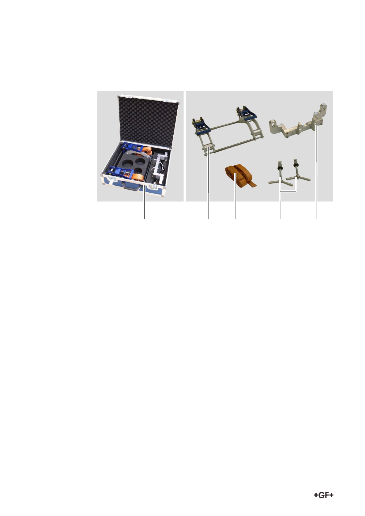
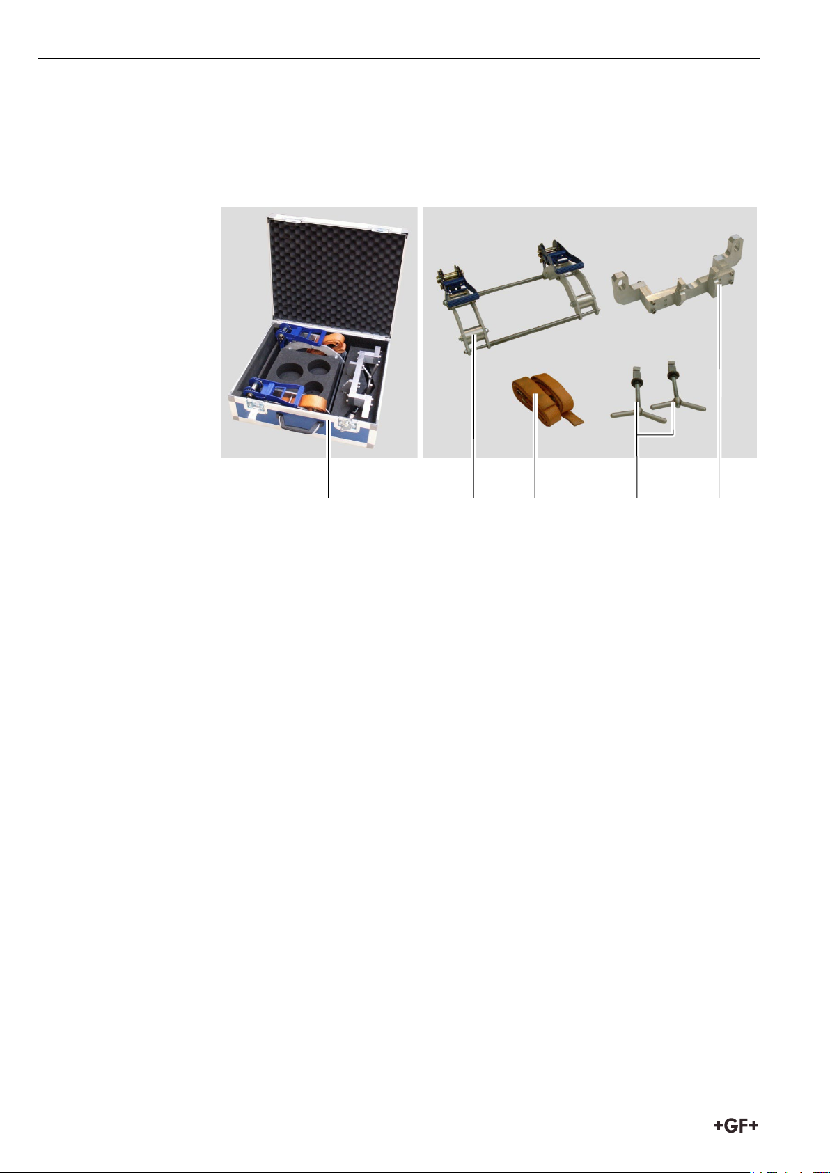
1 Transportkoffer mit Inhalt
2 Spannvorrichtung Topload
3 Spanngurte (2 x)
4 Spanngriffe (2 x)
5 Spannbügel
Gewicht mit Koffer
19,5 kg
Abmasse in cm (L x B x H)
60 x 52 x 19
2 Aufbau des Produkts
2.1 Topload 400
1 2 5 3 4
2.2 Technische Daten Topload 400
4
Page 9
Bedienungsanleitung Spannvorrichtung Topload 2 Aufbau des Produkts
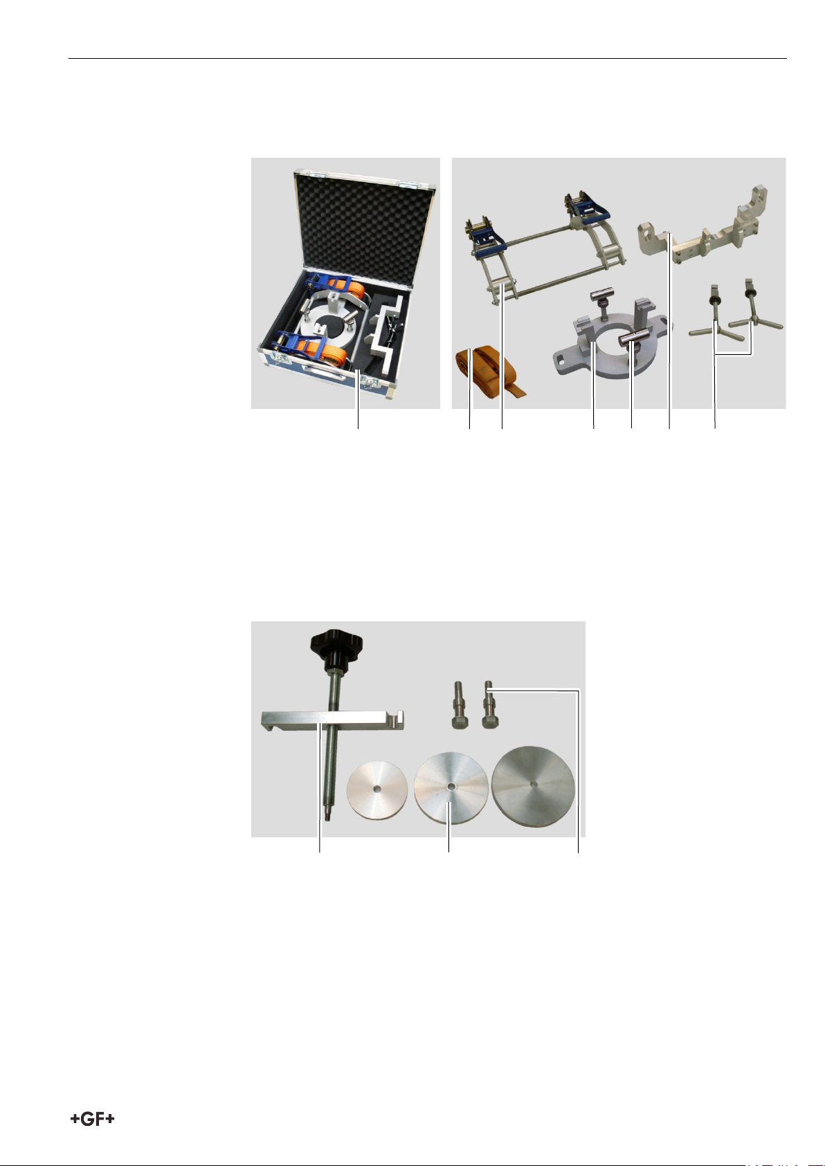
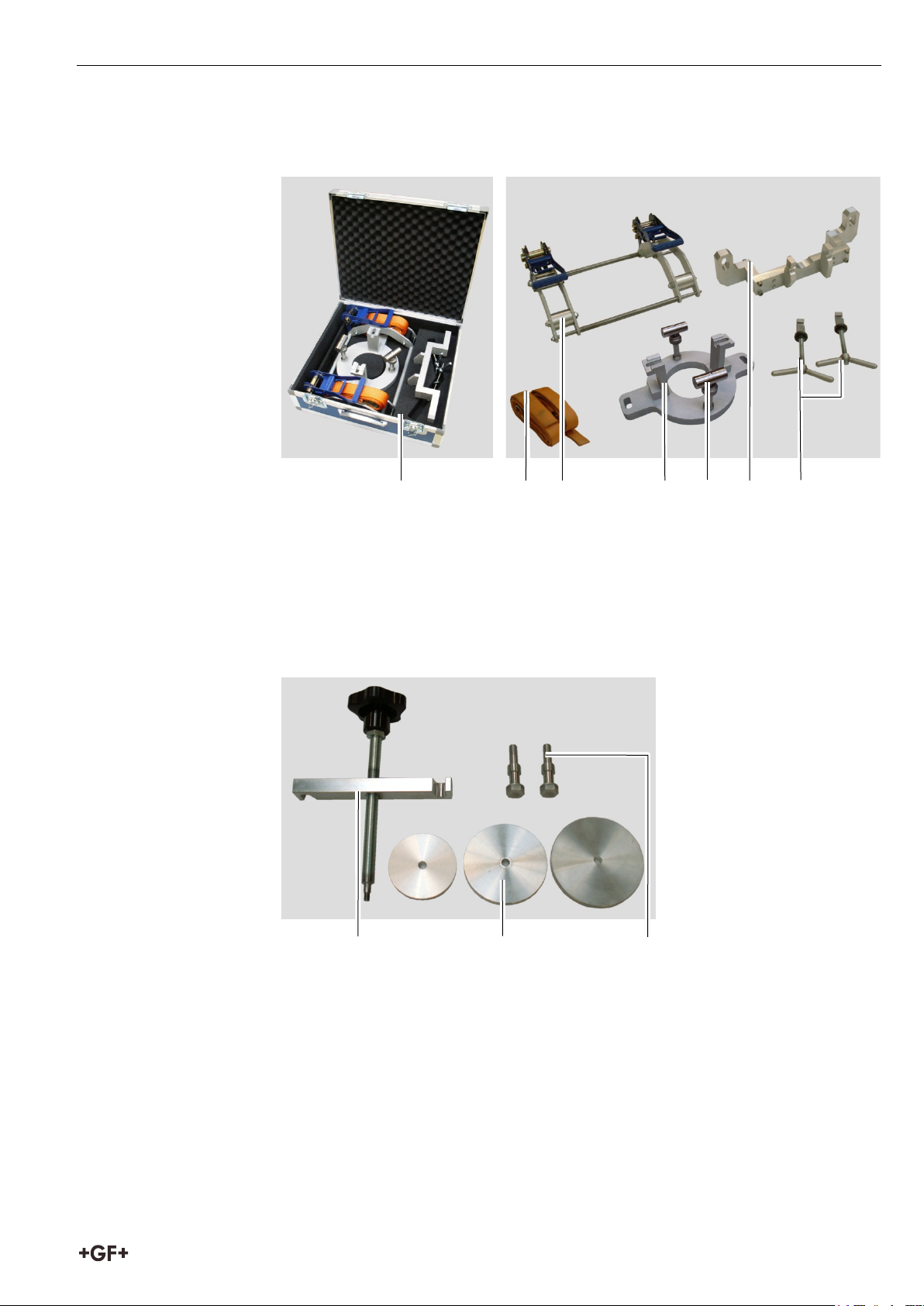
1 Transportkoffer mit Inhalt
2 Spanngurte (2 x)
3 Spannvorrichtung Topload
4 Spannaufsatz
5 Anschlagschraube
6 Spannbügel
7 Spanngriffe (2 x)
8 Spannbalken
9 Auswechselbare Druckscheiben für jede Abgangsdimension
(90 mm / 110 mm / 125 mm)
10 Schrauben (2 x)
Gewicht mit Koffer
24 kg
Abmasse in cm (L x B x H)
60 x 52 x 19
10
2.3 Topload 630
5 3 4 2 6 1 7
8 9
2.4 Technische Daten Topload 630
5
Page 10
3 Vorbereitung und Montage Bedienungsanleitung Spannvorrichtung Topload
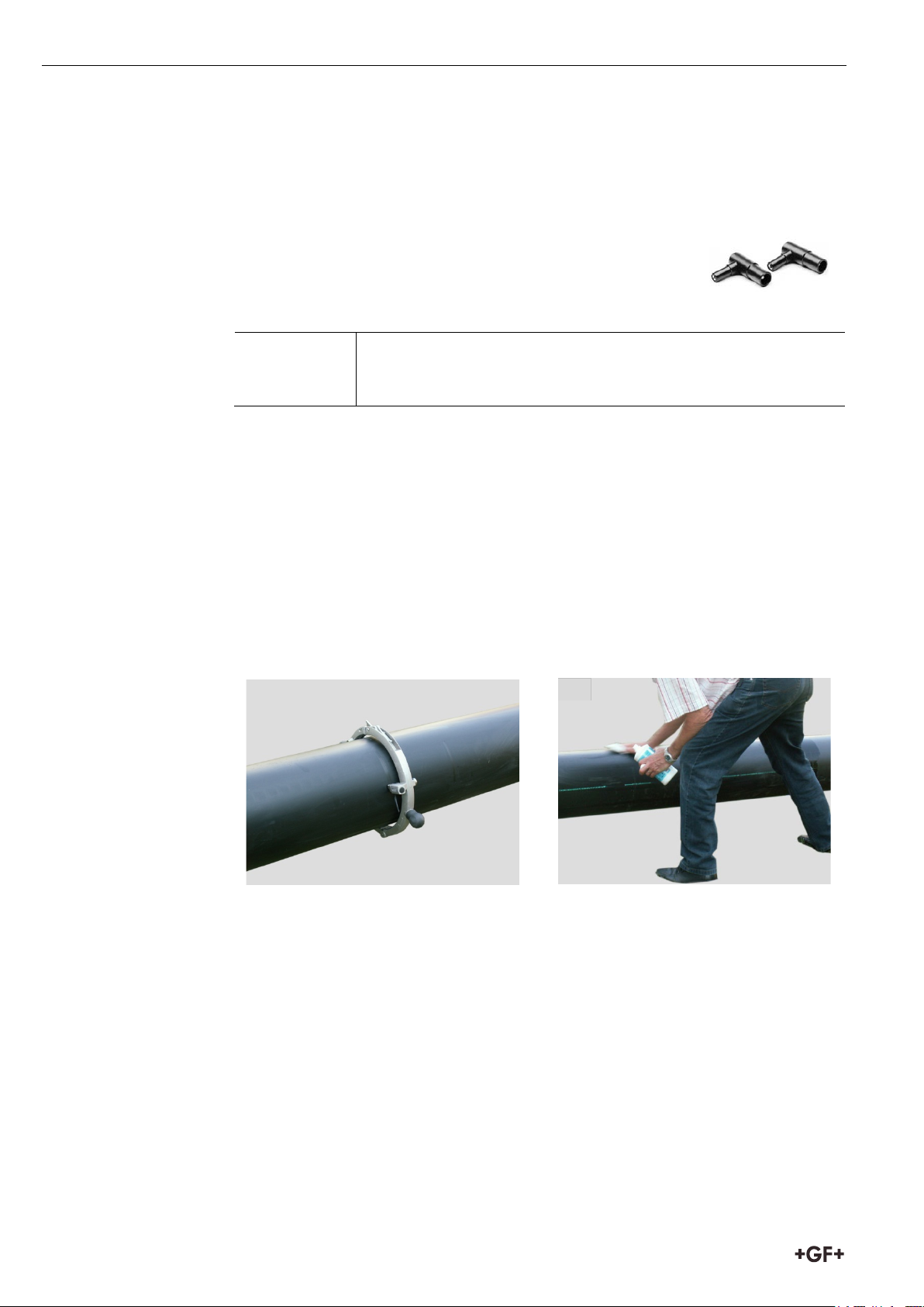
Für die Schweissung sind Winkelstecker (4 mm)
Wichtig
2
3
3 Vorbereitung und Montage
3.1 Vorbereitung
erforderlich (Codenr. 799350340).
VORSICHT Mangelhafte Schweissverbindung
Ungenügende Vorbereitungsmassnahmen können zu einer
mangelhaften Schweissverbindung führen.
1. Den Arbeitsbereich auf dem PE Rohr grob reinigen.
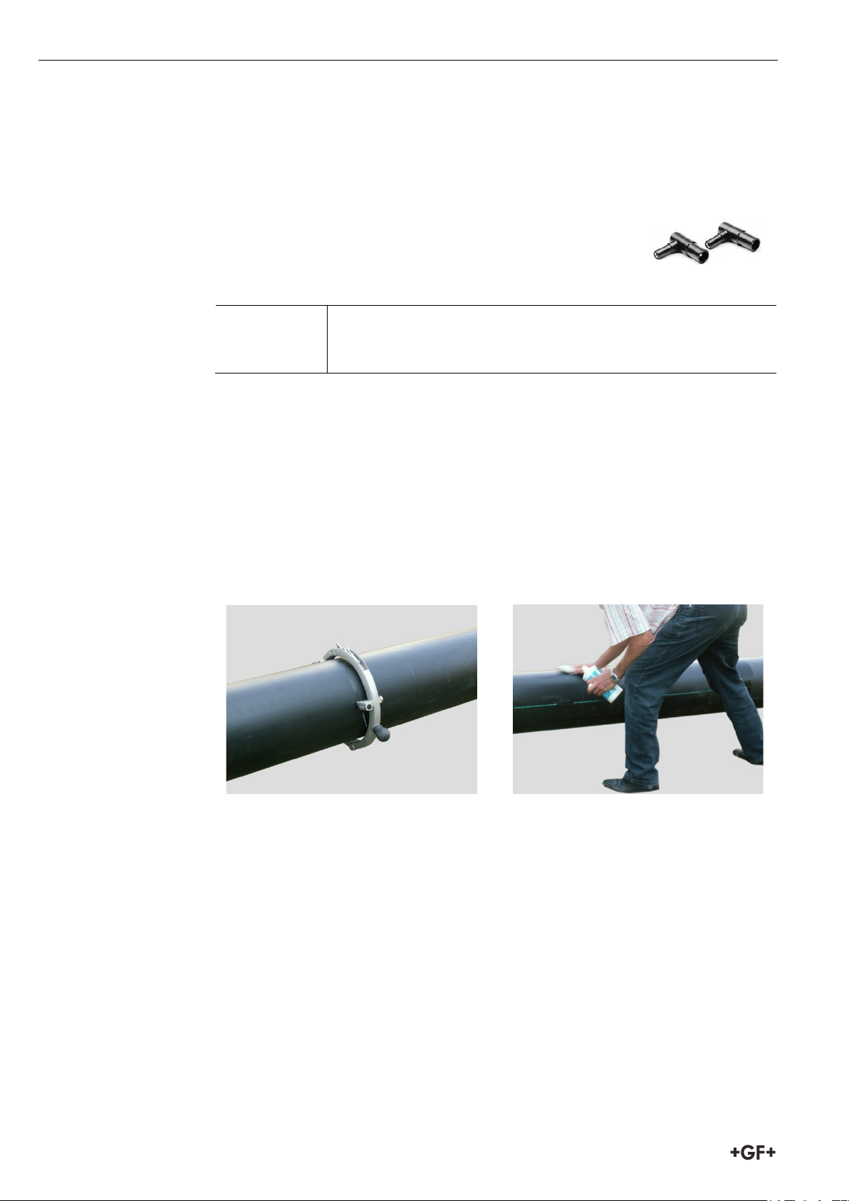
2. Das PE Rohr mit Rotationsschälgerät schälen. Min. Spanabtrag von 0.2mm
sowie min. zulässigen Rohraussendurchmesser beachten.
Wir empfehlen das Rotationsschälgerät "RS" (Codenr. 790136014 für d280
bzw. 790136015 für d315) oder das Schälgerät "RST 1000" (Codenummer
799 300 799) für d355 und grösser.
3. Das PE Rohr nur im geschälten Bereich mit Tangit PE Reiniger und
fusselfreiem, unbedruckten, sauberen Tuch in Umfangsrichtung reinigen.
Ablüften lassen. Schweissfläche nicht mehr berühren, Verschmutzungen
vermeiden.
6
Page 11
Bedienungsanleitung Spannvorrichtung Topload 3 Vorbereitung und Montage
4
3
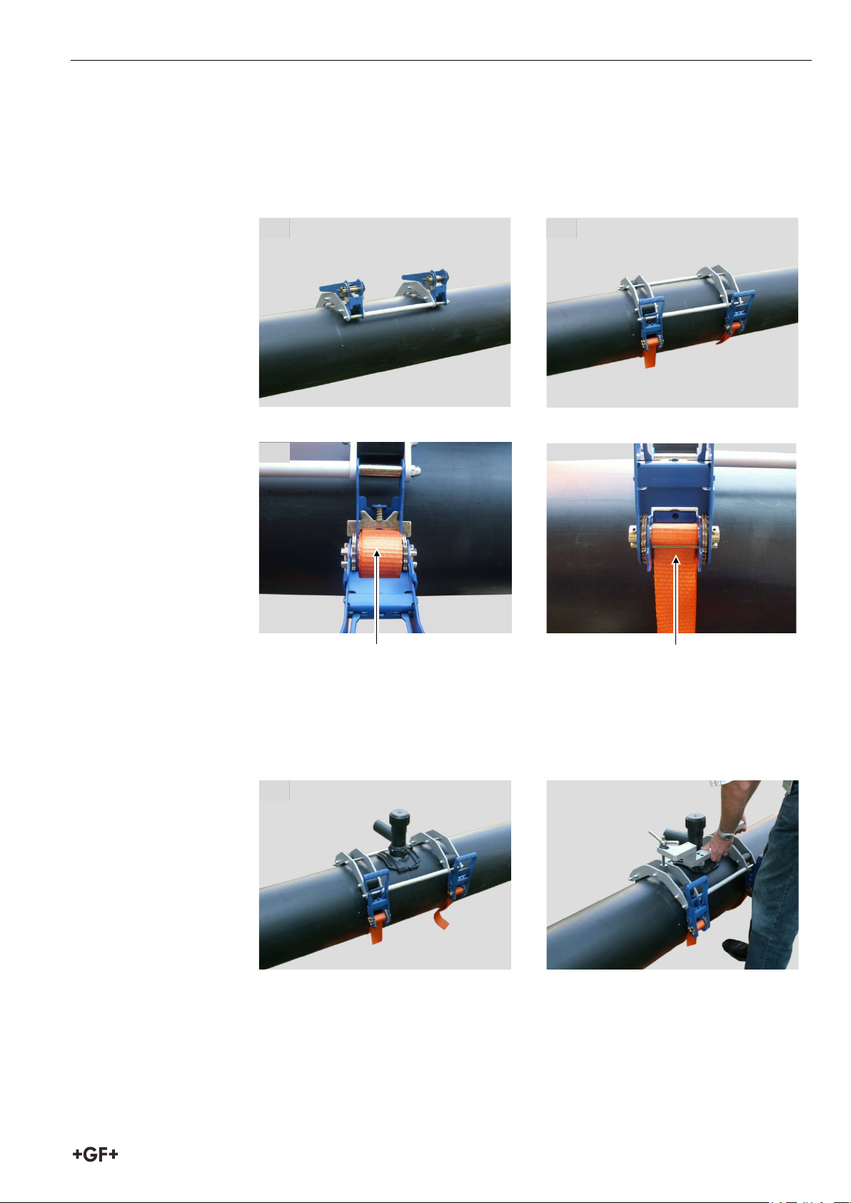
3.2 Montage Topload 400
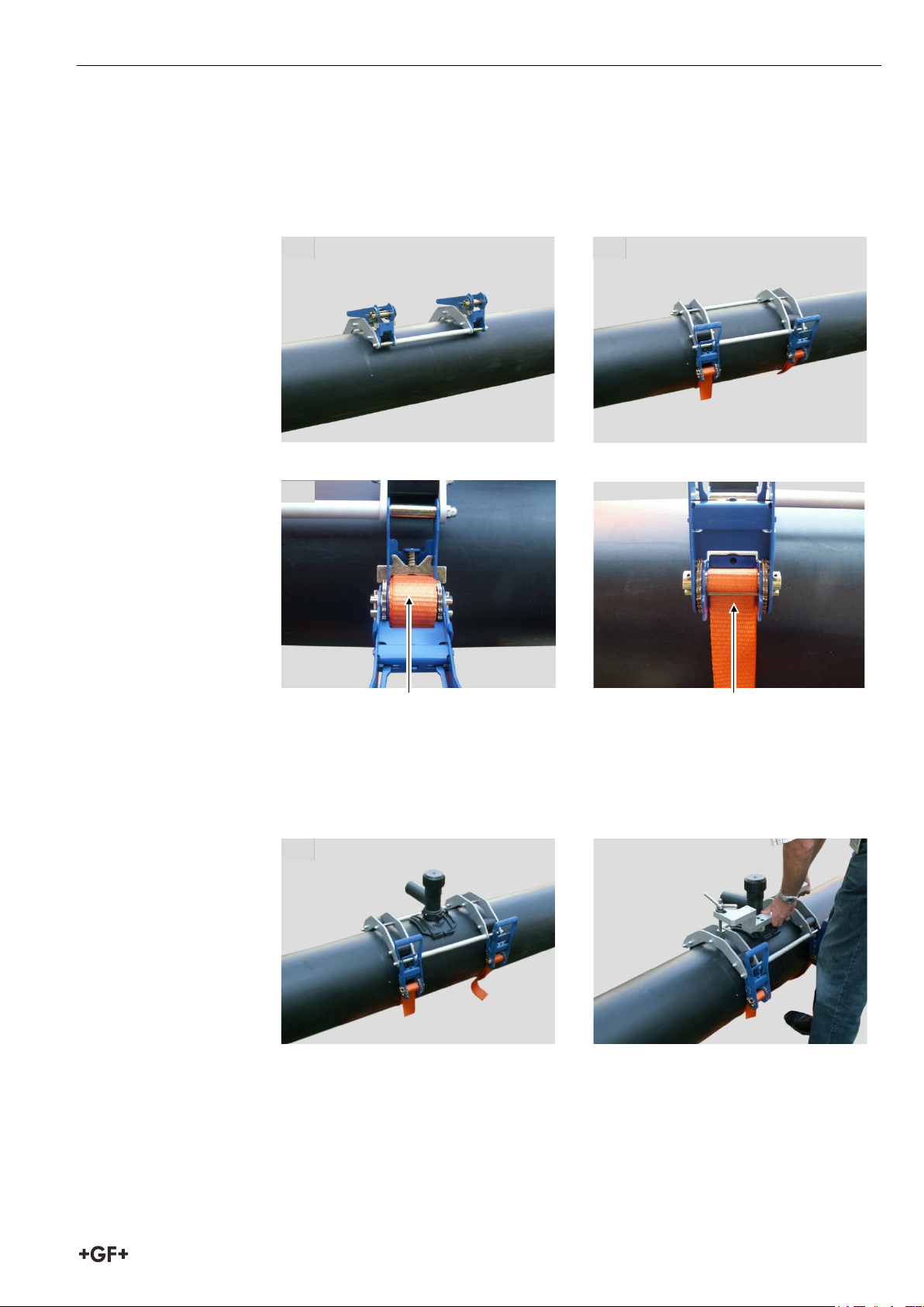
1. Spannvorrichtung Topload aufsetzen.
2. Spanngurte montieren und fest spannen.
2 1
3. Spanngurte festziehen.
Falsch
Richtig
4. Elektroschweissschelle unmittelbar vor der Montage aus Verpackung
nehmen ohne Schweissfläche zu berühren. Visuelle Prüfung des
Produktes.
Elektroschweissschelle auflegen und mit Spannbügel ausrichten.
7
Page 12
3 Vorbereitung und Montage Bedienungsanleitung Spannvorrichtung Topload
Hinweis
Wichtig
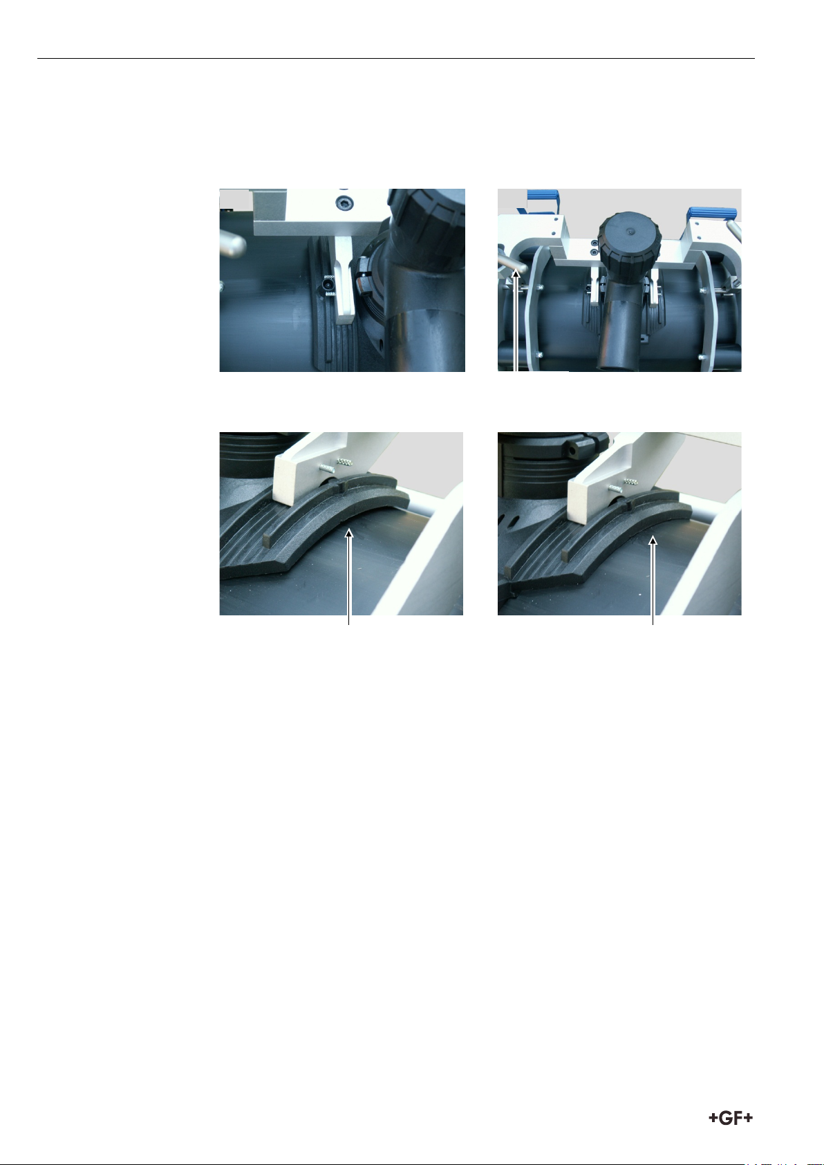
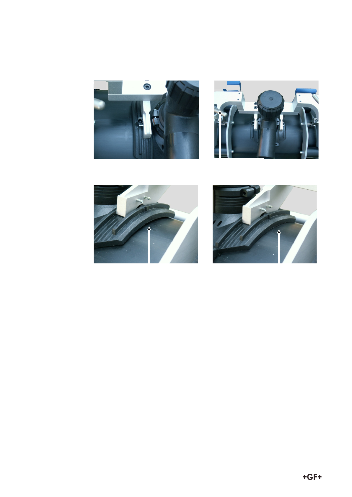
Richtig (Spalt < 0,5 mm)
5
6
5. Darauf achten, dass Kontaktstecker in der richtigen Position liegen.
6. Elektroschweissschelle mit Hilfe der Spanngriffe gleichmässig und fest auf
das Rohr spannen.
Spanngriff
Falsch
Die Montageanleitung für Schellen und Anbohrventile aus dem „Georg Fischer
Technischen Handbuch; Rohrleitungssysteme für die Versorgung“ sind für die
Schweissung und die weiteren Schritte zu beachten.
8
Page 13
Bedienungsanleitung Spannvorrichtung Topload 3 Vorbereitung und Montage
7
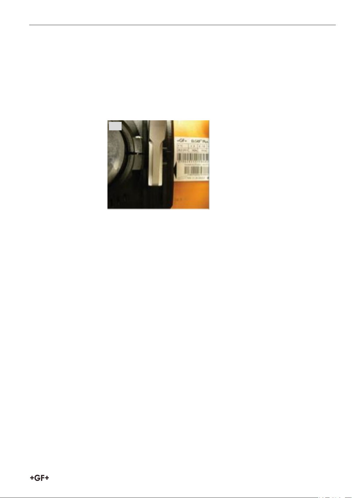
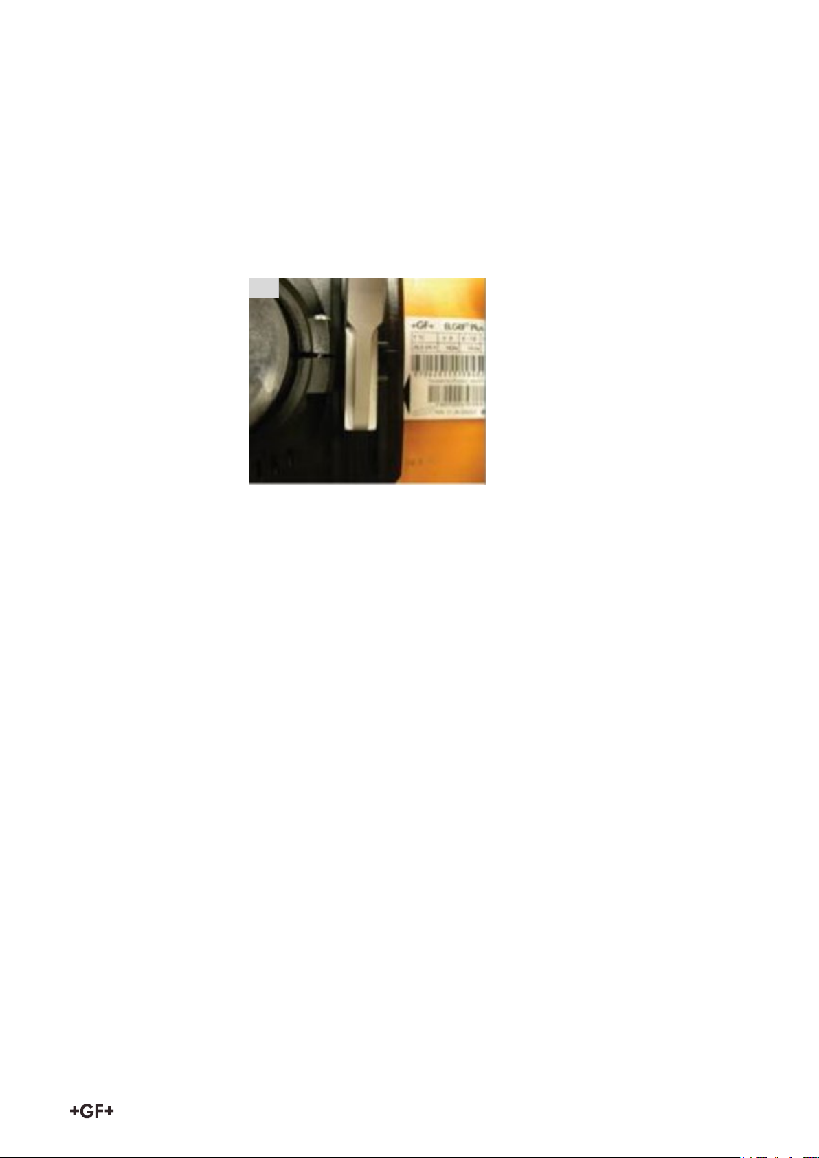
7. Nach der Montage darf maximal ein umlaufender Spalt von 0.5 mm
vorhanden sein. Dies wird durch Einschieben einer sauberen
Spaltprüfkarte geprüft.
Dazu den Schweissdatenträger je einmal links und rechts im
Scheitelbereich zwischen Rohr und Schelle bis zur Pfeilspitze (ca.5 mm)
einschieben. Mit Spanngriffen gleichmässig spannen, bis die Spaltprüfkarte
fest klemmt. Anschliessend nur so weit lösen, bis die Spaltprüfkarte mit
leichtem Zug herausgezogen werden kann.
7
8. Elektroschweissgerät anschliessen und Schweissung starten.
9. Schweissprozess überwachen.
10. Ende des Schweissprozesses und Abkühlzeit abwarten.
9
Page 14
3 Vorbereitung und Montage Bedienungsanleitung Spannvorrichtung Topload
Hinweis
1
2
3
4
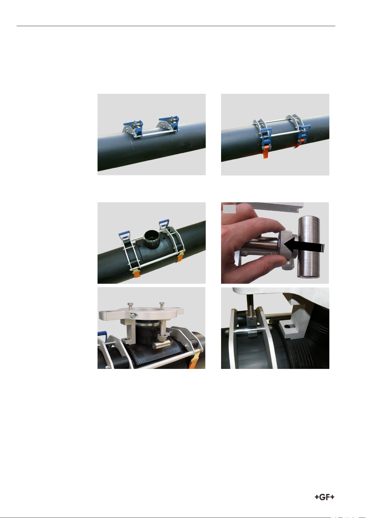
3.3 Montage Topload 630
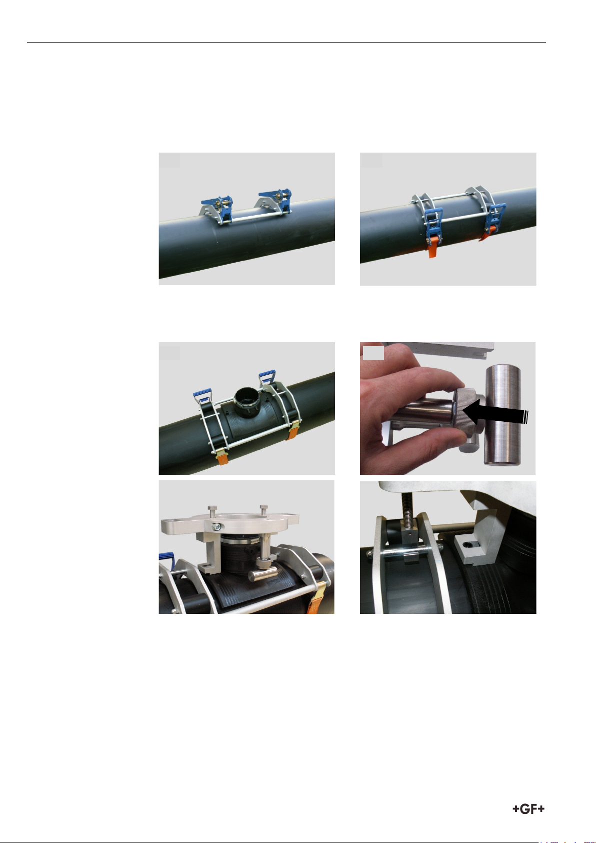
1. Spannvorrichtung Topload aufsetzen.
2. Spanngurte anlegen und vorspannen.
3. Anschlussfitting auflegen und mit Spannaufsatz ausrichten.
4. Anschlagschraube zurück drehen.
Darauf achten, dass Kontaktstecker des Fittings in der richtigen Position liegen
und zugänglich sind.
10
Page 15
Bedienungsanleitung Spannvorrichtung Topload 3 Vorbereitung und Montage
5 6 7
8
9
10
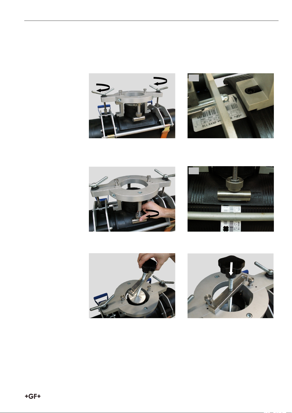
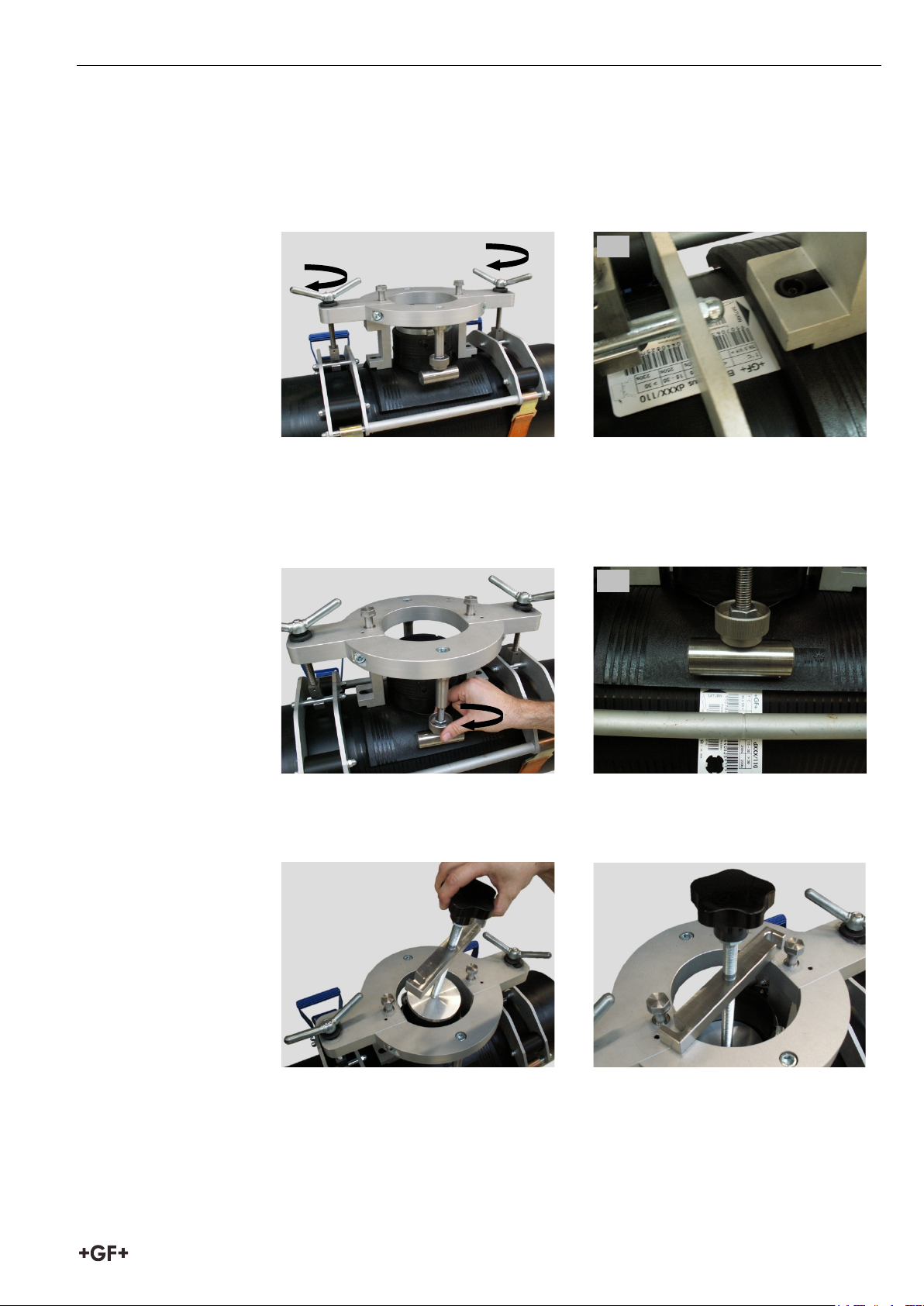
5. Spanngriffe mit der Hand gleichmässig anziehen.
6. Spaltmass zwischen Anschlussfitting und Rohr in der Mittelachse
kontrollieren. Magnetkarte kann dafür verwendet werden;
max. 1 cm Einstecktiefe; siehe Markierung
auf Magnetkarte.
7. Anschlagschrauben mit der Hand gleichmässig anziehen.
8. Spaltmass kontrollieren. Magnetkarte kann dafür verwendet werden;
max. 1 cm Einstecktiefe; siehe Markierung
auf Magnetkarte.
9. Spannbalken mit Druckscheibe einsetzen.
10. Auf Anschlag drücken.
11
Page 16
3 Vorbereitung und Montage Bedienungsanleitung Spannvorrichtung Topload
11
12
13
14
15
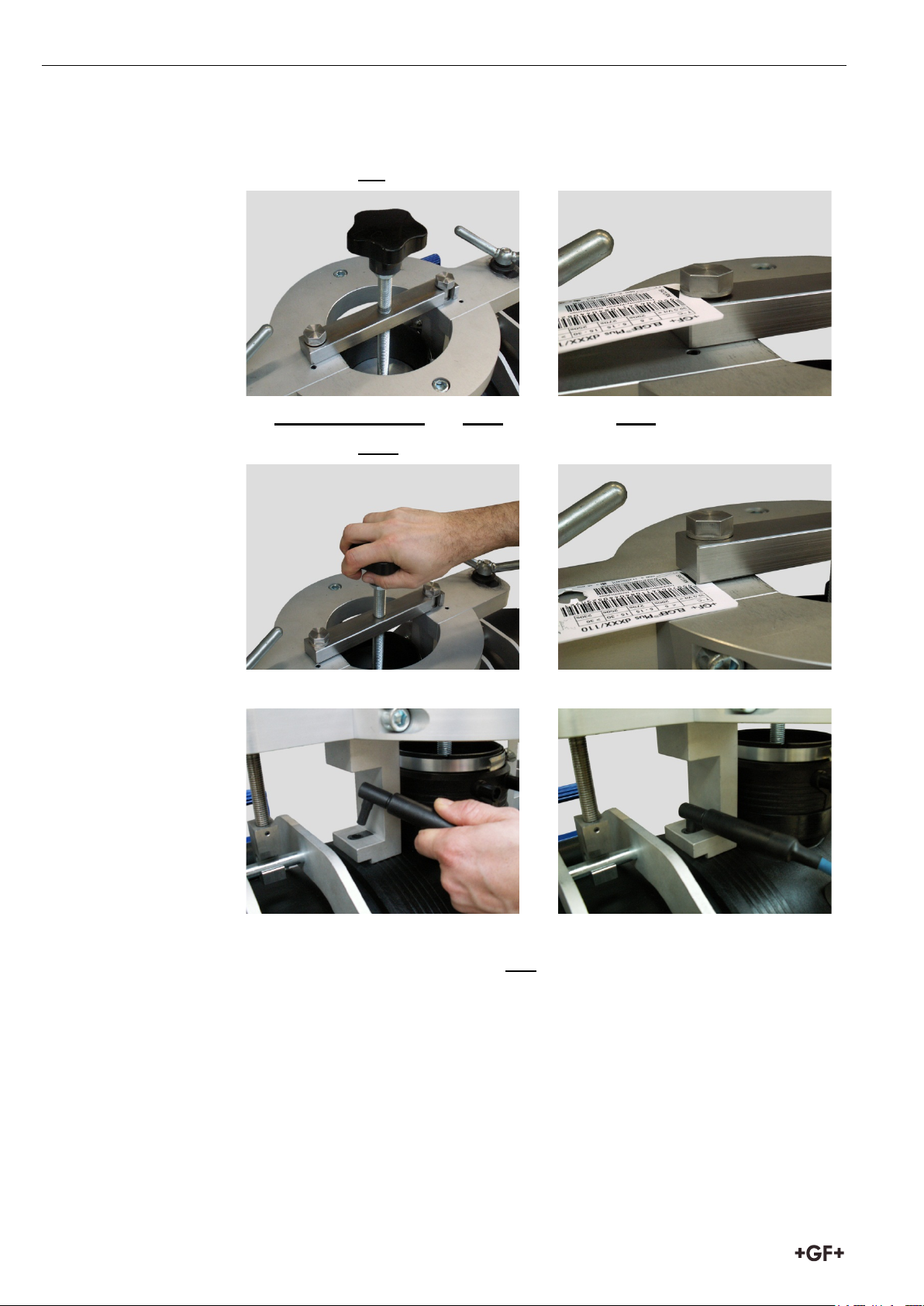
11. Auf Position bringen.
12. Spaltmass vor dem Anziehen kontrollieren.
13. Spanner von Hand und ohne übermässiger Kraft anziehen.
14. Spaltmass nach dem Anziehen kontrollieren.
15. Elektroschweissgerät anschliessen und Schweissung starten.
16. Schweissprozess überwachen.
17. Ende des Schweissprozesses und Abkühlzeit abwarten.
12
Page 17
Bedienungsanleitung Spannvorrichtung Topload 4 Wartung
Wichtig
Wichtig
3.4 Demontieren
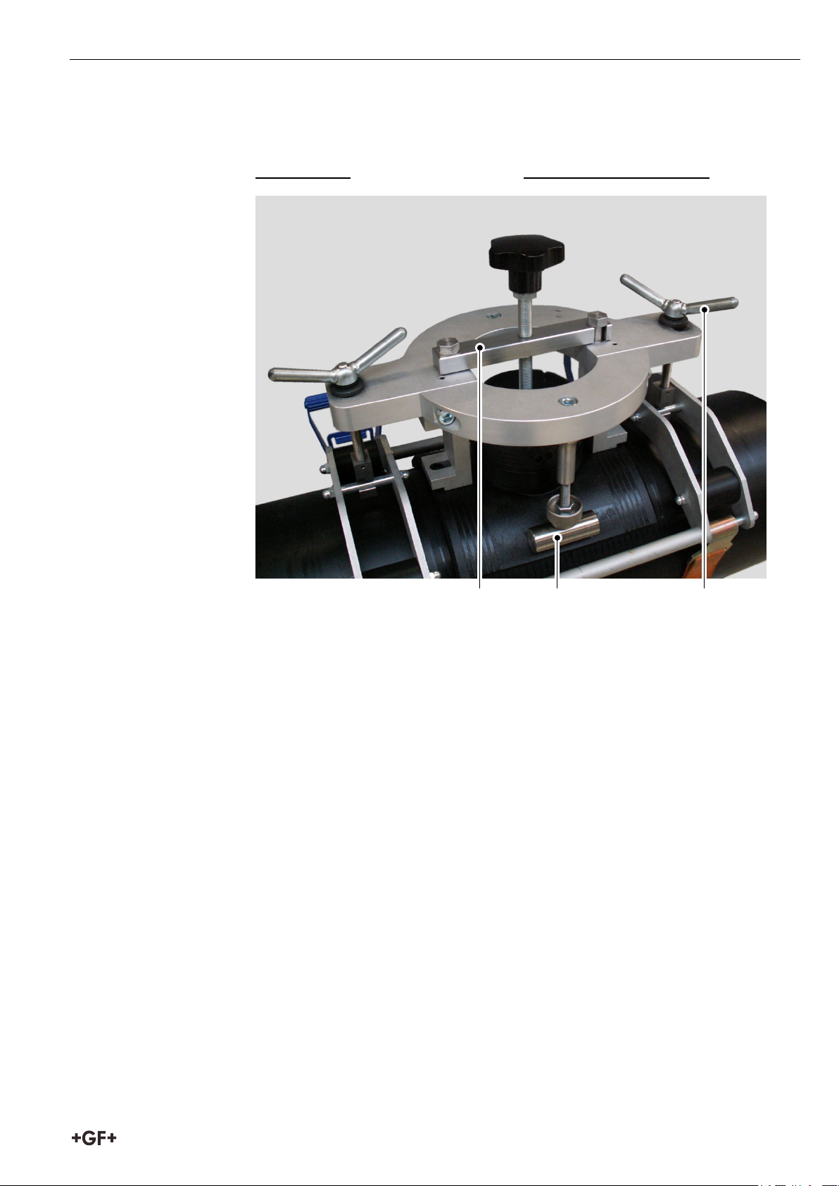
Demontieren der Spannvorrichtung in umgekehrter Reihenfolge
1. Spannbalken
2. Anschlagschrauben
3. Spanngriffe
Die Montageanleitung für Anschlussfittings aus dem „Georg Fischer
Technischen Handbuch; Rohrleitungssysteme für die Versorgung“ sind für die
Schweissung und die weiteren Schritte zu beachten.
1 2 3
4 Wartung
4.1 Service/Kundendienst
Für die Behebung von Störungen wenden Sie sich bitte direkt an unsere für
Sie zuständige Niederlassung. Das Adressenverzeichnis finden Sie auf der
Rückseite dieser Anleitung.
13
Page 18
5 Ersatzteile Bedienungsanleitung Spannvorrichtung Topload
5 Ersatzteile
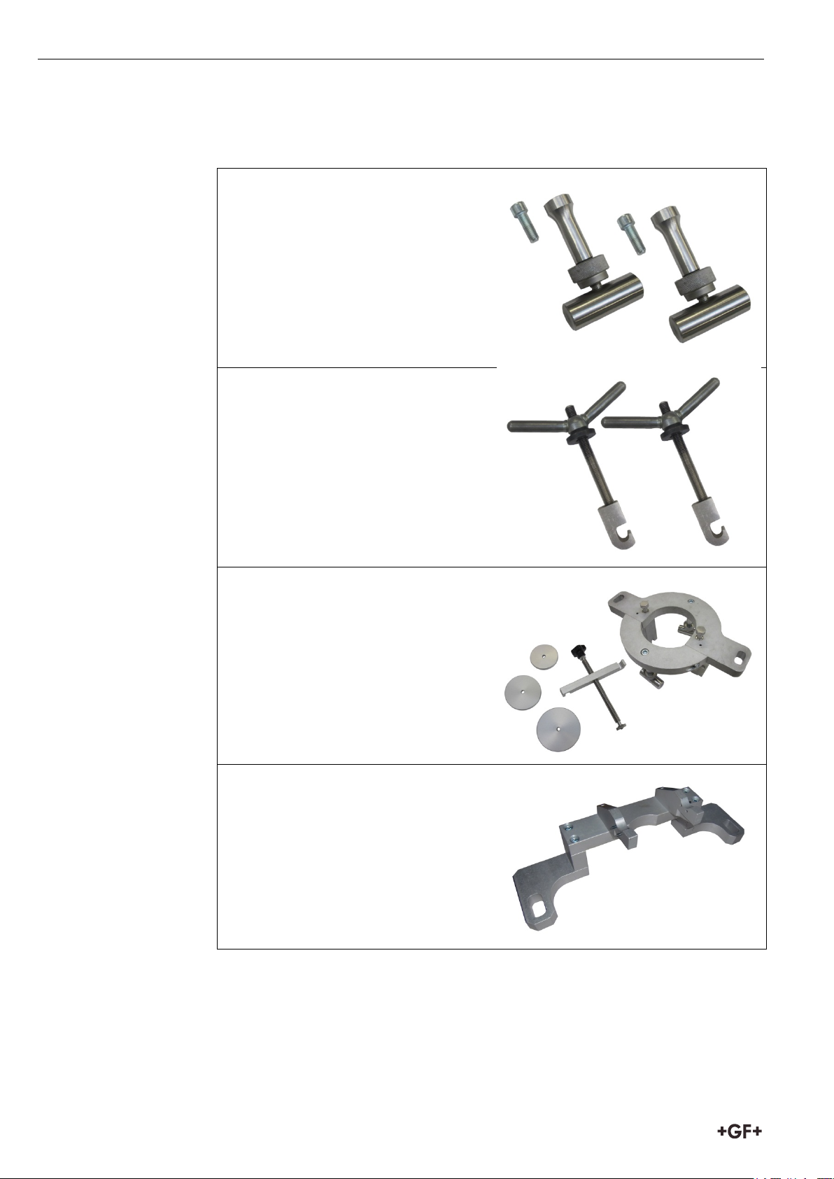
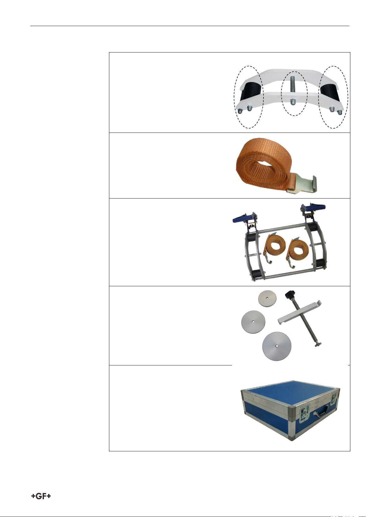
700235100
Anschlag Kit
700235101
Spanngriff Kit
799350476
Spannbalken Kit
700235103
Spannbügel
14
Page 19
Bedienungsanleitung Spannvorrichtung Topload 5 Ersatzteile
700235104
Distanzhalter Kit
799350478
Spanngurt
700235106
Spannvorrichtung Kit
700235107
Druckstück Kit
700235108
Transportkoffer
15
Page 20

1100670
GFDO_8240_DE_EN_3a (07/2019)
© Georg Fischer Piping Systems Ltd.
CH-8201 Schaffhausen 2019
Printed in Switzerland
Page 21
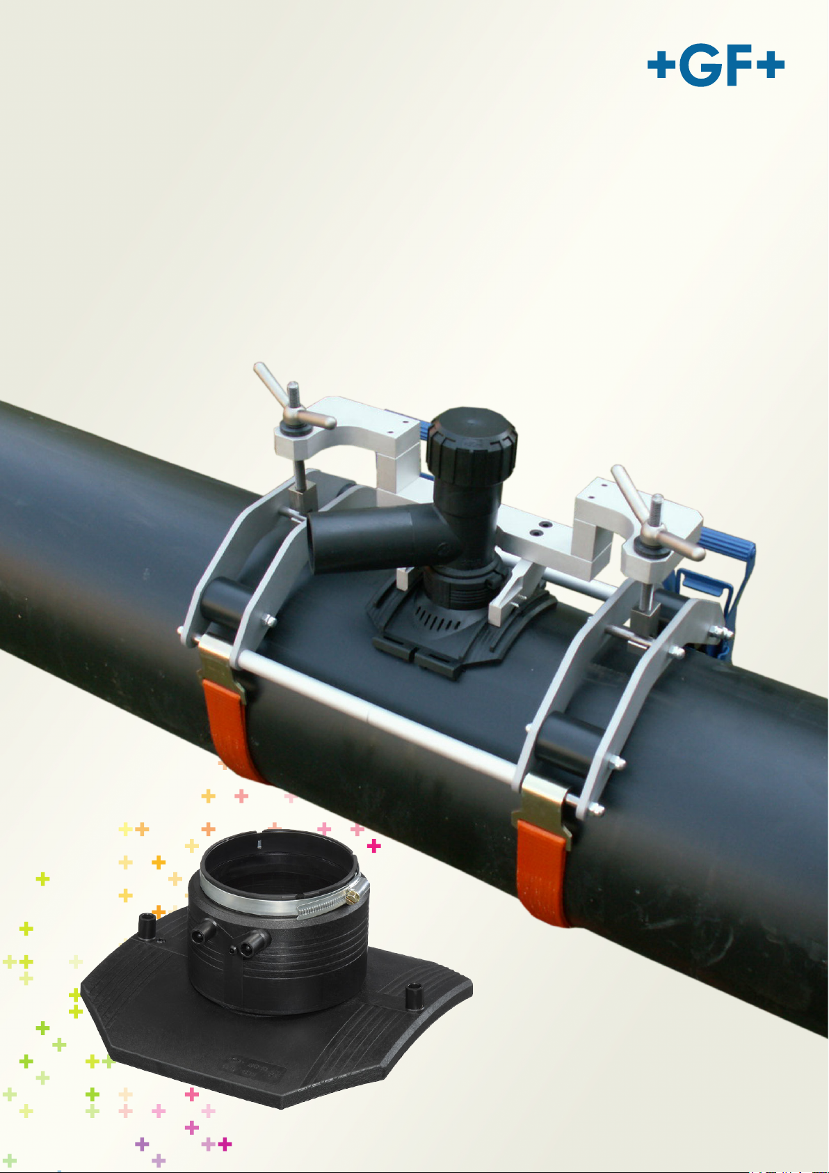
GF Piping Systems
Operating instructions
Clamping device
Topload 400 Code 799.350.475
Topload 630 Code 799.350.477
Page 22

All rights reserved, in particular the rights of duplication and distribution as well as translation.
Duplication and reproduction in any form (print, photocopy, microfilm or electronic) require the written
permission of Georg Fischer Piping Systems Ltd.
Page 23

Operating instructions Clamping device Topload Table of contents
0
1
1
1
1
3
3
3
2
4
4
4
5
5
3
6
6
7
10
13
4
13
13
5
14
Table of contents
Page
About this manual
0.1 Warning instructions
0.2 Other symbols and notices
Safety instructions
1.1 Proper use
1.2 General safety measures
Product design
2.1 Topload 400
2.2 Technical Information Topload 400
2.3 Topload 630
2.4 Technical Information Topload 630
Preparation and Assembly
3.1 Preparation
3.2 Assembly Topload 400
3.3 Assembly Topload 630
3.4 Dismount
Maintenance
4.1 Service and Support
Spare parts
I
Page 24
Table of contents Operating instructions Clamping device Topload
II
Page 25
Operating instructions Clamping device Topload 0 About this manual
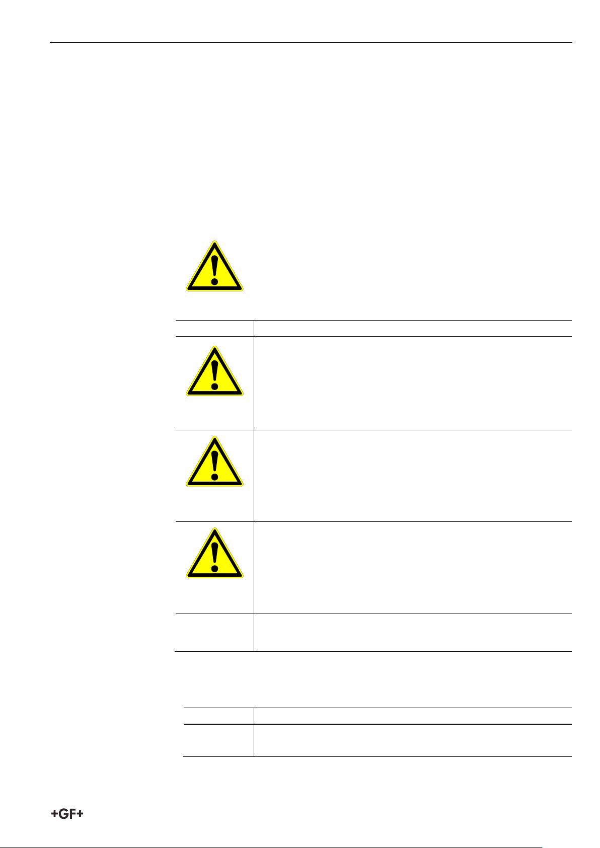
This is the warning symbol. It warns you of dangers of injury.
Symbol
Meaning
Symbol
Meaning
Important
This notice contains especially important information.
0 About this manual
The warning notices, symbols and their meanings as used in this manual are
explained below to help you quickly understand the format of this instruction
manual and how to use the machine safely.
0.1 Warning instructions
Warning notices are used in this manual to inform you of possible injuries or
damage to property. Please read them and always abide by these warnings!
Follow all measures, which are marked by the safety character,
in order to avoid injuries or death.
Imminent accute danger!
Failure to comply could result in death or extremely serious
injury.
DANGER
WARNING
CAUTION
CAUTION
Prohibited (if applicable).
Ways to prevent the danger.
Possible accute danger!
Failure to comply could result in serious injury.
Prohibited (if applicable).
Ways to prevent the danger.
Possible accute danger!
Failure to comply could result in serious injury.
Dangerous situation!
Failure to comply could lead to injury or damage to property.
0.2 Other symbols and notices
Attention
1
Page 26

0 About this manual Operating instructions Clamping device Topload
1.
Call for action in a particular sequence. You must do
Single call for action. You must do something here.
Call for action under certain circumstances. You must do
something here.
something here if the condition beforehand has been fulfilled.
2
Page 27

Operating instructions Clamping device Topload 1 Safety instructions
1 Safety instructions
The toploader is designed in accordance with modern technical practices. Any
use for another purpose other than that described in this instruction may lead
to personal injury either to the operator or to third parties. In addition, damage
may be caused to the equipment or other objects.
Thus:
• Only use the equipment when in perfect technical condition and follow all
safety instructions very closely.
• Keep these instructions complete and together with the equipment.
• All generally recognised accident preventative measures must be
observed at all times.
1.1 Proper use
• Clamping device Topload 400
– ELGEF Plus electrofusion saddles for dimension d 280 mm – 400 mm
with outlet d63 mm
• Clamping device Topload 630
– ELGEF Plus electrofusion saddles for dimension d 280 mm – 400 mm
with outlet d63 mm
– ELGEF Plus Branch fitting for dimension d 280 mm – 630 mm with outlet
d90/110/125 mm
• The operator is wholly responsible for all damage or injury caused by the
use of the equipment for purposes other than those intended.
1.2 General safety measures
• Only use the dimensions and materials mentioned in this instruction.
Other materials may only be used after consultation and agreement from
the Georg Fischer Support Service.
• Only use original replacement parts and materials from Georg Fischer.
• The equipment should be checked daily for any optical signs of damage
and defects. Damage and defects are to be remedied immediately.
3
Page 28
2 Product design Operating instructions Clamping device Topload
1 Storage box
2 Topload
3 Securing straps (2 x)
4 Clamp arms (2 x)
5 Clamp
Weight, including storage box
19,5 kg
Dimensions in cm (L x B x H)
60 x 52 x 19
2 Product design
2.1 Topload 400
1 2 5 3 4
2.2 Technical Information Topload 400
4
Page 29
Operating instructions Clamping device Topload 2 Product design
1 Storage box
2 Securing straps (2 x)
3 Topload
4 Clamping attachment
5 Stop screws (2 x)
6 Clamp
7 Clamp arms (2 x)
8 Tie beam
9 Exchangeable pressure disks for each outlet dimension
(90 mm / 110 mm /125mm)
10 Screws (2 x)
Weight, including storage box
24 kg
Dimensions in cm (L x B x H)
60 x 52 x 19
10
2.3 Topload 630
1 7
5 3 4 2 6
8 9
2.4 Technical Information Topload 630
5
Page 30
3 Preparation and Assembly Operating instructions Clamping device Topload
For the fusion angle adapters (4 mm) are required
Important
2
3
3 Preparation and Assembly
3.1 Preparation
(Codeno. 799350340).
CAUTION Defective fusion connection
Insufficient preparations can lead to a defective fusion
connection.
1. Clean working area on the PE pipe roughly.
2. Peel the PE pipe with a rotary peeler. Note min. shaving thickness of 0.2
mm as well as the min. allowable outside pipe diameter.
We recommend the use of Rotary peeler "RS" (Code-no. 790136014 for
d280 respectively 790136015 for d315) or the Peeling tool "RST 1000"
(Code-no. 799300799) for sizes d355 and above.
3. Clean pipe only in the peeled area with Tangit PE cleaner and lint-free,
colorless and clean cloth in circumferential direction, let the cleaner
exhaust. Do not touch the fusion zone and avoid contamination.
6
Page 31
Operating instructions Clamping device Topload 3 Preparation and Assembly
4
3
3.2 Assembly Topload 400
1. Mount Topload tool on pipe.
2. Attach and fully tighten security straps
2 1
3. Tight securing straps.
incorrect right
4. Remove electrofusion saddle immediately before installation from
packaging without touching the fusion zone. Examine for possible damage
of product.
Position electrofusion saddle and set clamping device.
7
Page 32
3 Preparation and Assembly Operating instructions Clamping device Topload
Note
Important
Correct (gap < 0.5 mm)
6
5
5. Ensure that the terminals are in the correct position.
6. Clamp electrofusion saddle evenly and firmly to the pipe using the clamping
handles.
Clamping handles
incorrect
The assembly instructions for saddles and tapping valves described in the
Georg Fischer Technical handbook ” Distribution Piping Systems” are to be
closely followed for the fusion process and other steps.
8
Page 33
Operating instructions Clamping device Topload 3 Preparation and Assembly
7
7. Following assembly, the gap between saddle and pipe around the
periphery should never exceed a maximum of 0.5mm. The size of this gap
may be easily checked sliding a clean test card card into the space
between the two components.
On the crown of the pipe, slide the magnetic card between pipe and saddle,
moving the card to the left and right, up to the arrowhead (approx. 5mm).
Tighten clamp handles evenly until the card is pinched. Then loosen slowly
until the card can be just eased out.
8. Connect fusion unit and start fusion process.
9. Monitor fusion process.
10. Await end of fusion process and cooling time.
9
Page 34
3 Preparation and Assembly Operating instructions Clamping device Topload
Note
1
2
3
4
3.3 Assembly Topload 630
1. Mount topload tool on pipe.
2. Attach and pre-tighten securing straps.
3. Mount electrofusion saddle and align using clamp.
4. Turn back the stop screws.
Ensure pin terminals of fittings are in the right position and accessible.
10
Page 35
Operating instructions Clamping device Topload 3 Preparation and Assembly
5 6 7 8 9
10
5. Tighten clamp arms manually and equally.
6.
Control gap between fitting and pipe in middle axis.
Magnetic data carrier can be used; maximum 1 cm insertion depth;
see marking
on data carrier.
7. Tighten stop screws manually and equally.
8. Control gap.
Magnetic data carrier can be used; maximum 1 cm insertion depth;
see marking
on data carrier.
9. Insert tie beam.
10. Push down.
11
Page 36
3 Preparation and Assembly Operating instructions Clamping device Topload
11
12
13
14
15
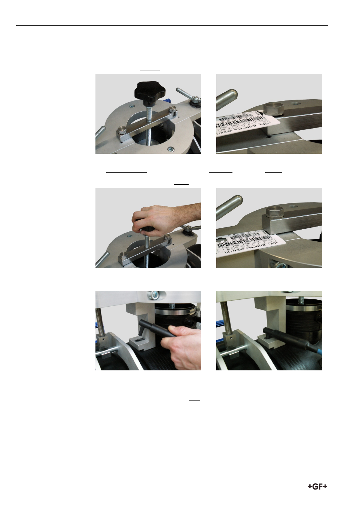
11. Place in position.
12. Watch gap before tightening
.
13. Hand-tighten wheel manually and without excessive effort.
14. Watch and control gap after tightening.
15. Connect fusion unit and start fusion process.
16. Monitor fusion process.
17. Await end of fusion process and cooling time.
12
Page 37
Operating instructions Clamping device Topload 4 Maintenance
Important
Important
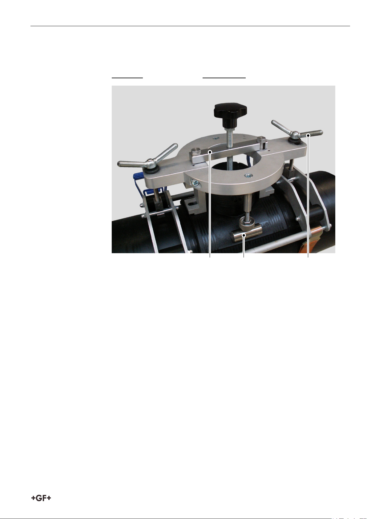
3.4 Dismount
Dismount the Topload tool in reverse order
1. Tie beam
2. Stop screws
3. Clamp arms
The assembly instructions for branch fittings described in the Georg Fischer
Technical handbook ” Distribution Piping Systems” are to be closely followed
for the fusion process and other steps.
1 2 3
4 Maintenance
4.1 Service and Support
Please contact our sales company or representative in your area should any
correction of defects be necessary. The appropriate list of addresses can be
found on the rear cover of this publication.
13
Page 38
5 Spare parts Operating instructions Clamping device Topload
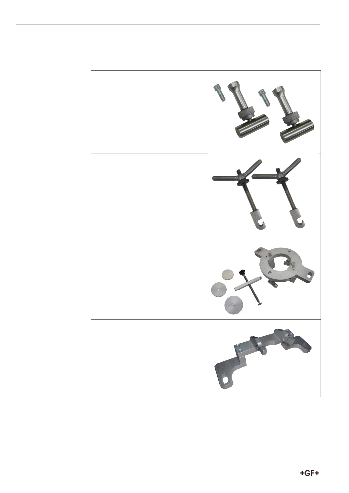
5 Spare parts
700235100
Stop Kit
700235101
Clamping handle kit
799350476
Clamping bar kit
700235103
Clamping bracket
14
Page 39
Operating instructions Clamping device Topload 5 Spare parts
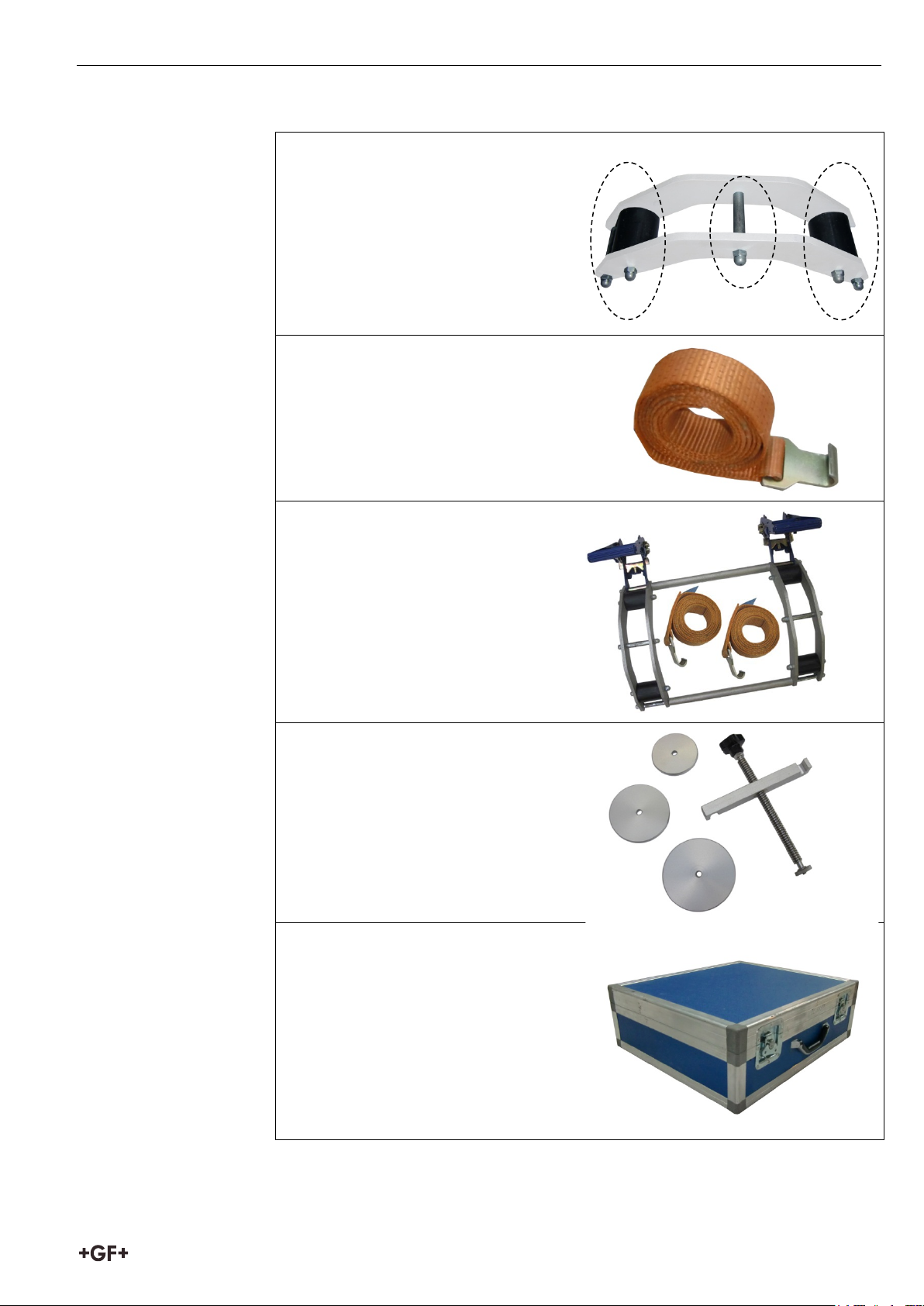
700235104
Spacer kit
799350478
Tension belt
700235106
Clamping device kit
700235107
Compressor kit
700235108
Transport case
15
Page 40

1100670
GFDO_8240_DE_EN_3a (07/2019)
© Georg Fischer Piping Systems Ltd.
CH-8201 Schaffhausen 2019
Printed in Switzerland
 Loading...