

Page 1
Planungsunterlage TSA160 Datei 84338PuTSA160_GB_200999_.p65
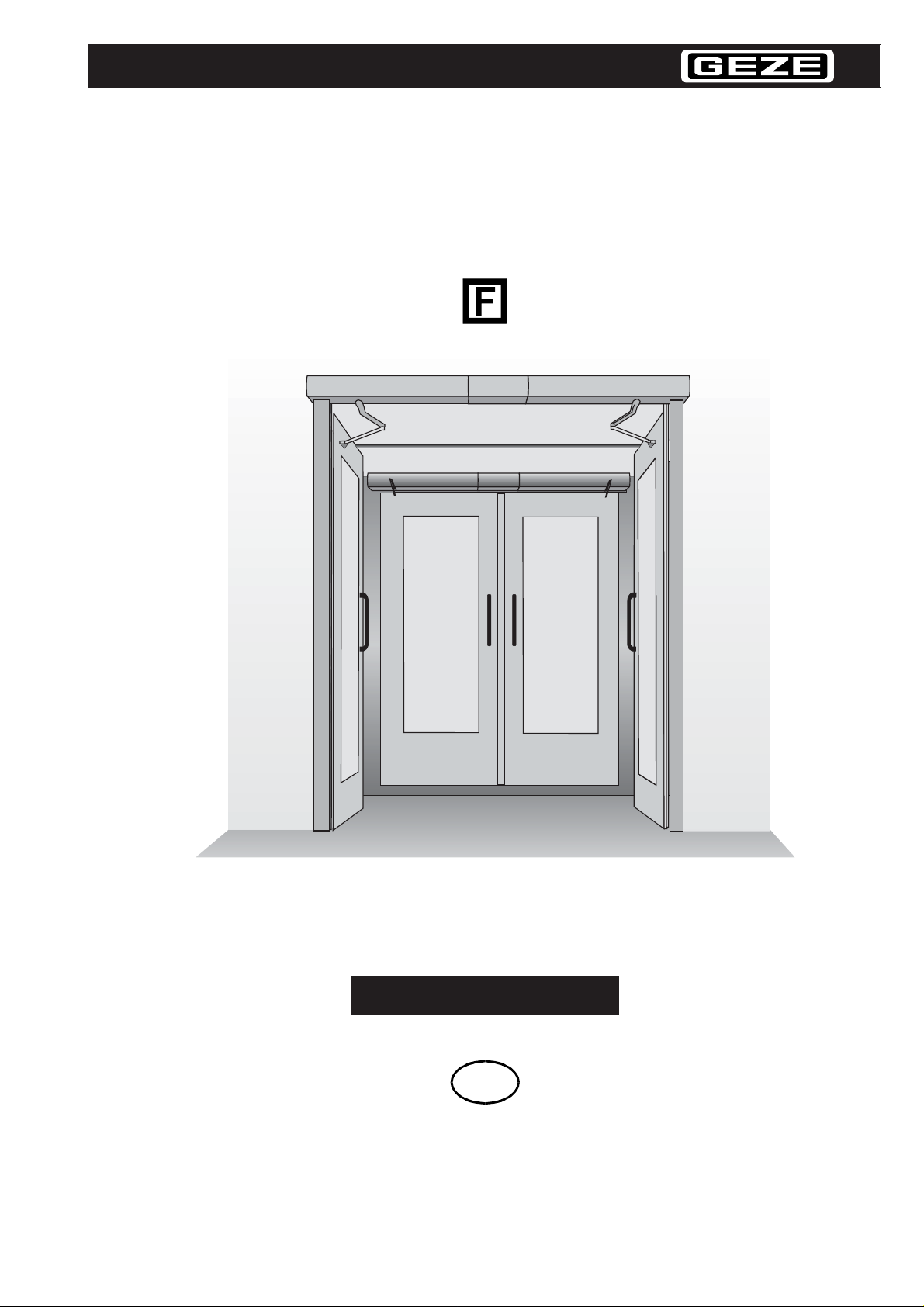
TSA 160
Swing Door Drive for Automatic Doors
GEZE
Planning document
GB
1
Page 2
Planungsunterlage TSA160 Datei 84338PuTSA160_GB_200999_.p65
MATERIALPRÜFUNGSAMT NORDRHEIN-WESTFALEN
Prüfstelle, Überwachungsstelle und Zertifizierungsstelle gemäß § 28 BauO NW
CERTIFICATE OF CONFORMITY
Reg.-No. 12 9820 - DO 14.1
This is to certify in accordance with § 22 para.2 No. 2 of the Building Code (Landesbauordnung) for the Land
Baden-Württemberg, that
the building products: Swing door drive ‘’GEZE TSA 160 ’ ’ complies with
the requirements
• set forth by the technical rules in accordance with the Technical Schedule A part 1 (edition 98/2),
consecutive number 6.14 of DIN 18 263-4
the manufacturer:
GEZE GmbH
Postfach 1263
D-71229 Leonberg
the production plant: GEZE GmbH
Reinhold-Vöster-Str . 21-29
D-71229 Leonberg
in accordance with the results of the
• product tests carried through by the MPA NRW
• internal product control carried through by the producer
• foreign control carried through by the MP A NRW
The manufacturer is therefore entitled to mark the building products, the packing or the delivery note with the
sign of conformity (Ü-sign) in accordance with the ordinance regulating conformity signs.
Dortmund, 12.12.2000
Marsbruchstraße 186 • Dortmund-Aplerbeck • Postanschrift: 44285 Dortmund • Telefon (0231) 4502-0 • Telefax (0231) 4502 586
2
Page 3

Planungsunterlage TSA160 Datei 84338PuTSA160_GB_200999_.p65
Contents
Fields of application 4
Product features 5
List of product variants 6
Swing door drive for smoke and fire-proof doors TSA 160 F 7
Accessories for TSA 160 F on fire-proof doors 8
TSA 160 Invers and TSA 160 Z Invers 9
TSA 160 WC-compartments for the handicapped 10
Description of drive 11
GEZE
System description 14
Technical Features 15
Connection possibilities for actuation elements 16
Safety sensors 17
Side view and installation dimensions TSA 160 18
Side view and installation dimensions TSA 160 and TSA 160 F-IS 20
Side view and installation dimensions TSA 160 pulling 22
Side view and installation dimensions, 1- and 2- leafs
TSA 160 Z and TSA 160 Z-IS 24
Cable plan single-leaf door 26
Cable plan single-leaf smoke and fire-proof door,
incl. central smoke control unit 27
Cable plan double-leaf door incl. integrated closer control 28
Cable plan double-leaf door incl. central smoke control unit 29
Cable plan single and double-leaf with door control unit TZ 220 30
Cable plan TSA 160 WC-compartment for the handicapped 31
3
Page 4
Planungsunterlage TSA160 Datei 84338PuTSA160_GB_200999_.p65
Fields of application
Where help is needed:
Hospitals, rehabilitation centres
Old-peoples homes as well as homes and workshops for disabled persons
Public buildings, airports, stations
Canteens, waiter’s swinging doors
Schools, kindergardens
Where energy has to be saved:
Exterior doors, corridor end doors
Draught-proof systems
Workshops, ateliers, studios
Where hygiene is required:
Food manufacturing shops, pharmaceutical industry
Hospitals, surgeries
Social rooms, toilets
Where safety is the first priority:
For safety locks and access control
For fire prevention purposes (fire and smoke prevention) type TSA 160 F on
single-leaf and double-leaf doors
Where comfort is the choice:
In shops
In banks
In public buildings
4
Page 5
Planungsunterlage TSA160 Datei 84338PuTSA160_GB_200999_.p65
Product features
TSA 160 is an electronically controlled, electrohydraulic swing door drive.
Opening is effected by a hydraulic pump system.The closing process is effected by a
closing spring mechanism and adjustable hydraulic valves.
Small exterior dimensions, i.e. the drive can also be installed with limited space
conditions.
The closing force is infinitely variable from EN size 3 to 6 acc. to EN 1154 for different leaf widths.
Max. leaf width 1400 mm
Max. door weight 250 kg
Systems can be used for either pushing or pulling versions (hinge side and opposite
hinge side)
GEZE
For single-leaf doors
TSA 160
only one system for door DIN left or DIN right (retrofittable) and usable for either
pulling or pushing version
TSA 160 F
for smoke and fire-proof doors, pushing
For double-leaf doors
Intermediate cover possible
TSA 160 - IS
including invisible closing sequenz control, concealed under the cover
TSA 160 F - IS
for smoke and fire-proof doors
TSA 160 - IS / TS
automatic 2nd closing leaf, 1st closing leaf with door closer function ”permanently
open” only.
The motor is activated by an electronic system:
Start-up as required incl. evaluation of the sensors and the control units in the periphery.
Same system for all doors in the house (single-leaf, double-leaf, fire-proof doors etc.)
reduces maintenance and installation work as well as stockkeeping of spare parts for
mechanical equipment.
5
Page 6
Planungsunterlage TSA160 Datei 84338PuTSA160_GB_200999_.p65
List of product variants
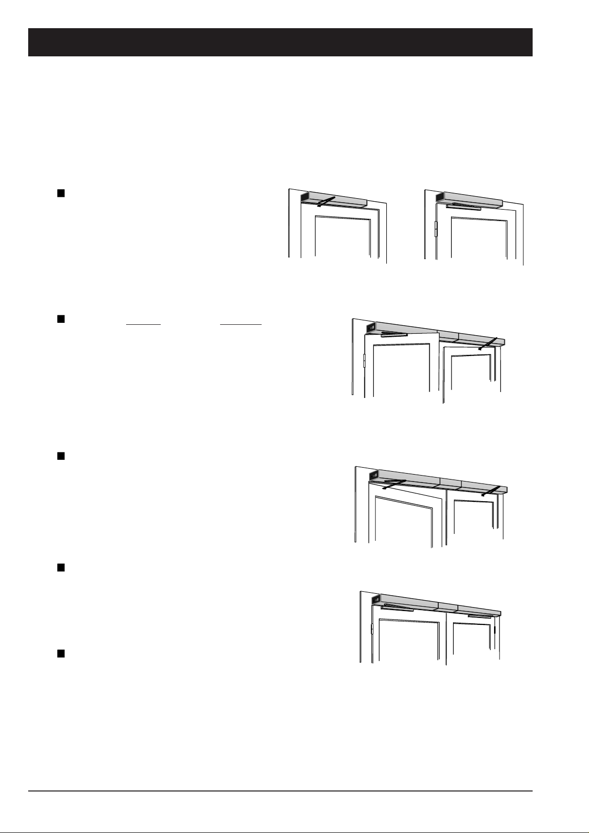
Swing door drive for interior and exterior doors
TSA 160
pulling or pushing
for single-leaf or double-leaf
single-action doors
Opposite hinge side pushing
TSA 160 pulling + TSA 160 pushing
for double-motion, double-leaf doors
TSA 160 - IS
pushing or pulling incl. integrated closer
control on double-leaf doors
TSA 160 / 162
as ”master/slave” combination with only one
combined control for both drives of
double-leaf doors
incl. linkage
Hinge side, pulling
incl. guide rail
Hinge side pulling incl. guide rail
Opposite hinge side pushing incl. linkage
Opposite hinge side, pushing
incl. linkage
TSA 160 - IS / TS
pushing or pulling incl. integrated closer control.
2nd closing leaf incl. automatic function,
1st closing leaf incl. door closer function and
Hinge side, pulling
incl. guide rail
permanently-open position
6
Page 7
Planungsunterlage TSA160 Datei 84338PuTSA160_GB_200999_.p65
GEZE
Swing door drive for smoke and fire-proof doors
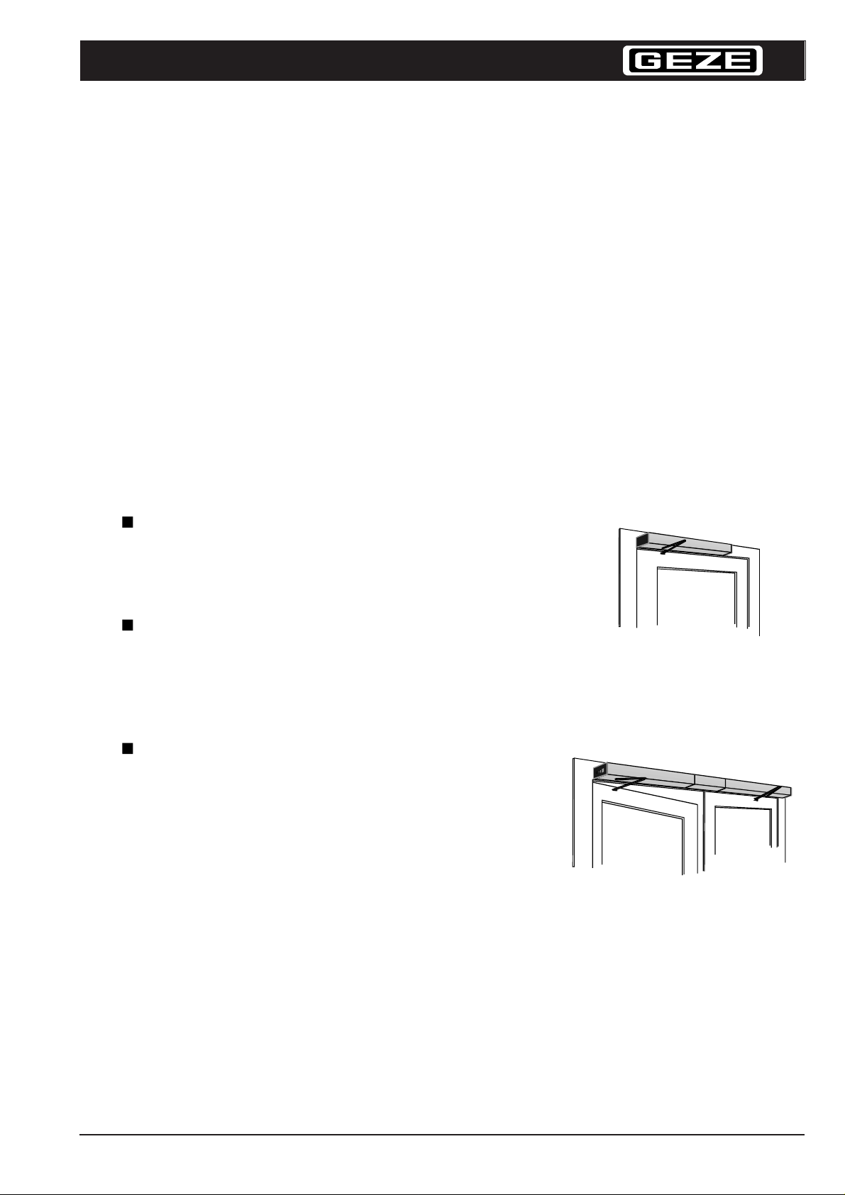
TSA 160 F
The TSA 160 F is a hold-open mechanism in accordance with the guidelines for hold-open
systems issued by DIBt *)
The drive system is used to automatically open and close fire-proof doors. The system can be
actuated via the usual pulse generators. Besides automatic opening and closing, the doors
can also be held in an open position.
In the case of fire, the automatic function or the hold-open function must be switched off by a
corresponding fire alarm system. The mains cable is interrupted by a mains PC board for
power cutoff (F-accessories) and the normal door closing function the drive is maintained.
Door closers with automatic opening function (swing door drive) in accordance with
DIN 18263 part 4 are therefore an integral part of hold-open mechanisms and require
approval by the building supervision authorities.
TSA 160 F
pushing incl. DIBt-approval for the use on
single-leaf smoke and fire-proof doors.
TSA 160 F-IS
pushing incl. integrated closer control;
incl. DIBt-approval for the use on
double-leaf doors.
TSA 160 F - IS / TS
pushing incl. integrated closer control;
incl. DIBt-approval for the use on double-leaf
doors, 2nd closing leaf incl. automatic function
1st closing leaf incl. door closer function and
permanently-open position.
*) DIBt: German Institute for Structural Engineering (Deutsches Institut für Bautechnik)
7
Page 8
Planungsunterlage TSA160 Datei 84338PuTSA160_GB_200999_.p65
Accessories for TSA 160 F on fire-proof doors
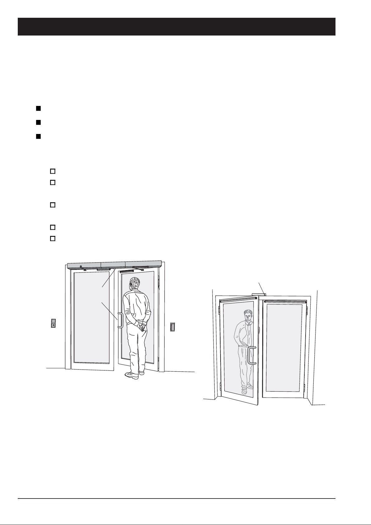
For
TSA 160 F
TSA 160 F - IS
TSA 160 F - IS / TS
the following items are required for the use on fire-proof doors:
Smoke switch with energy supply e.g. RSZ 6
probably additional smoke detectors in accordance with the guidelines for hold-
open mechanisms
break key (manually operated release button) in accordance with the guidelines
for hold-open
Interrupter
button
Emergency
cut-out
electric door opener, approved for fire-proof doors (customer)
Mounting plate TSA 160
RSZ6
Electric door
opener
Actuation
button
8
Page 9
Planungsunterlage TSA160 Datei 84338PuTSA160_GB_200999_.p65
GEZE
TSA 160 Invers and TSA 160 Z Invers
Functional description
Single or double-leaf doors are kept close by the escape route locking
mechanism. The door is monitored via an emergency exit system
which controls all safety-relevant functions. The doors are electrohydraulically closed and opened through spring force. This ensures
that the doors can be reliably opened and kept permanently open in
the case of power failure.
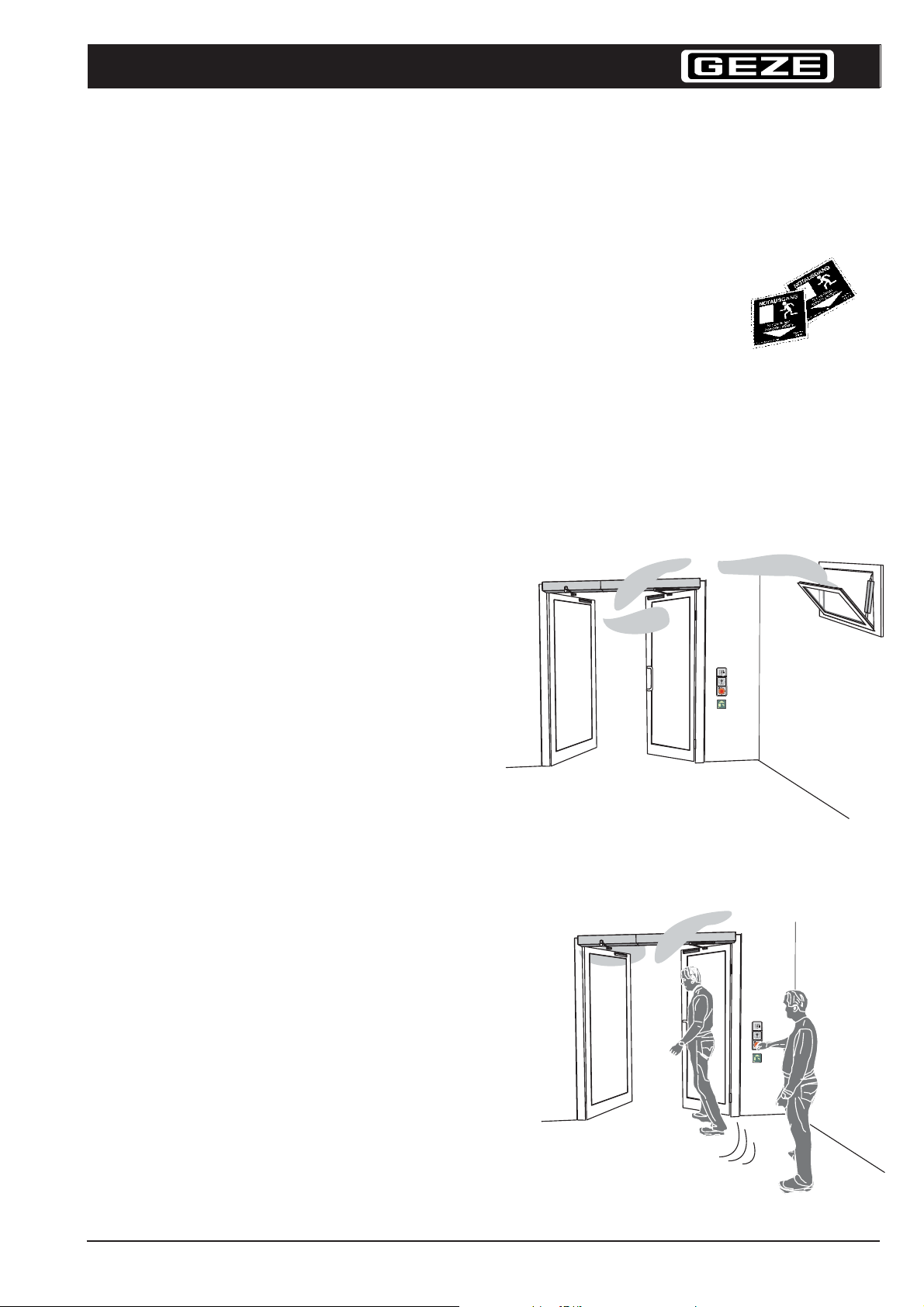
Automatic function
The system is released at the emergency exit system via the key-operated switch (or e.g.
card reader), which activates the actuation elements of the automatic door drives. As soon
as the sensors respond, the drives open
the doors through spring force. Upon
lapse of the pre-set hold-open time, the
doors close automatically with all safety
elements being active. This means that
the sensors will stop the movement of the
door if a person is within the swing of the
door and the door will not close until the
obstacle has been removed.
BURG
NurbeiGefahrbetätigen
NOTTASTE
Smoke/heat extracting system – fresh air
If an alarm has been released by the
smoke detector or the fire alarm system
the doors are immediately unlocked and
mechanically opened to allow secure
smoke extraction. The doors remain open
until the alarm has been reset.
Escape way function
If the red emergency button is operated by a
fleeing person, the doors are immediately
unlocked and mechanically opened through
spring force. Thus the escape route is free. The
operation of the emergency button at the same
time releases an alarm which is transmitted to
the control centre.
View of the door: opposite hinge side featuring
Smoke/heat extracting system
TSA 160 Z Invers
BURG
NurbeiGefahrbetätigen
NOTTASTE
9
Page 10
Planungsunterlage TSA160 Datei 84338PuTSA160_GB_200999_.p65
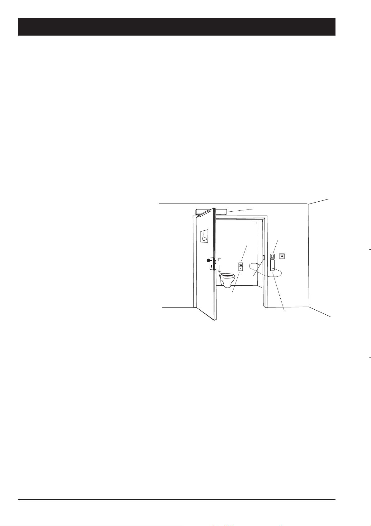
TSA 160 WC-compartments for the handicapped
Functional description
After the pad switch had been operated, the toilet door opens and closes automatically upon lapse
of a presettable hold-open time.
By operating the changeover switch inside the toilet cabin, the user activates the illuminated sign
“OCCUPIED“ outside the compartment as well as the control lamp at the changeover switch.
Simultaneously the interior and exterior pad switch is switched off. Thus the door can neither be
opened by a third person nor by the user himself by accident.
The live door opener prevents that the doors can be opened manually.
To leave the lavatory, the user again operates the changeover switch; the sign “ OCCUPIED“ out-
side the compartment as well as the
control lamp go out.
By operating the interior pad switch
“DOOR OPEN“, the door will immediately
open.
In the case of power failure the user has
the possibility to open the door manually
by pushing or pulling it open, the closedcircuit opener is unlocked.
The door can also be opened from inside
by operating the door handle even if the
system is live. In an emergency the door
can also be manually opened from outside using a key or by operating the
emergency cutout.
Illuminated sign
“OCCUPIED“
Changeover
switch
locked/unlocked
TSA160
Illuminated sign
“OCCUPIED“
Emergency
cutout
Door
opener
Pad switch “DOOR
OPEN“ (inside and
outside)
10
Page 11
Planungsunterlage TSA160 Datei 84338PuTSA160_GB_200999_.p65
Description of drive
Field of application:
For single-leaf or double-leaf swing doors made of metal, timber, all-glass
or PVC u
Type-tested for the use on single-leaf and double-leaf smoke and fire-proof doors,
pushing version
Outside dimensions of drive: W x H X D = 690 x 100 x 120 mm
Max. leaf width 1400 mm
Min. hinge centre TSA 160 F - IS 1470 mm
TSA 160 F- IS / TS 1260 mm
Max. weight of leaf 250 kg
GEZE
Max. soffit depth pushing function (TSA 160) 350mm
pulling function (TSA 160 Z) 200 mm
For dry rooms only, ambient temperature -10° to +60°C
Adjustable functions:
Opening speed: via hydraulic valve
Closing speed: within range 75° ... 0°
Opening and closing damping: via hydraulic valve
Latching action: via hydraulic valve
Closing force, infinitely: EN size 3 ... 6 (DIN 2 ... 5)
Approach delay: 0 – 5 seconds
Adjustable hold-open time: 0 ... 60 s
(via jumper 0...10; 10...60 s)
Door opening angle: max. 115°
* not required for TSA 160 Invers, the closing force is generated electrically
11
Page 12
Planungsunterlage TSA160 Datei 84338PuTSA160_GB_200999_.p65
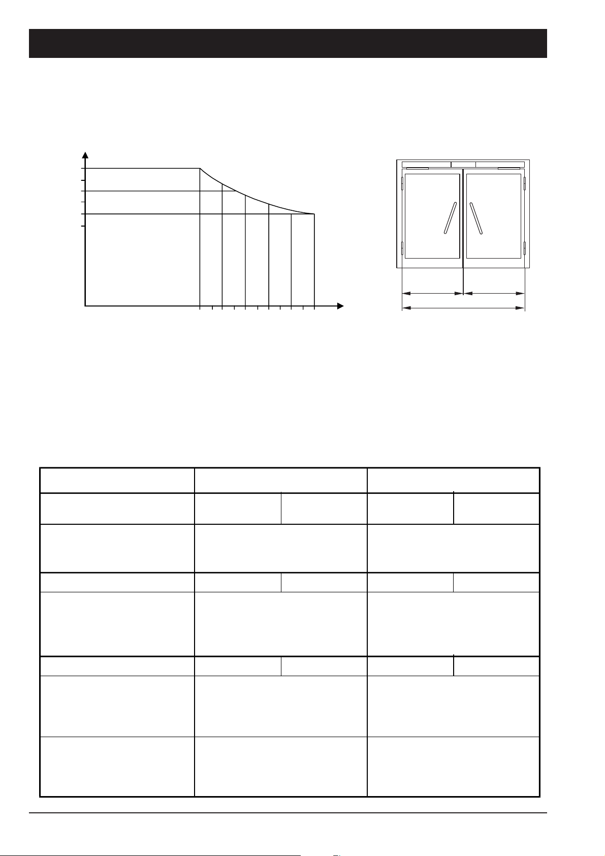
TSA 160 maximum leaf width as a function of leaf weight
Leaf width [mm]
1400
1200
1000
100 130 160 190 220 250
Leaf weight [kg]
Hint:
The doors have to be equipped with hinges suitable for automatic function.
A door stopper is recommended in any case.
pushing function
minimum spring
pre-tension
maximum spring
pre-tension
minimum spring
pre-tension
Closer size acc. to
EN 1154
Size 3 . . . . . . . . Size 6
Leaf width
Hinge centre [mm]
Leaf width
pulling function
maximum spring
pre-tension
Closing moments:
moment exerted by the
closing spring when door
is closed
Opening moments:
moment exerted by the
closing spring when door
is opened automatically
moment that has to be
exerted manually to open
the door
12
20 Nm . . . . . . > 60 Nm
8 Nm . . . . . . . 30 Nm
150 Nm . . . . . . . 90 Nm 70 Nm . . . . . . 40 Nm
35 Nm . . . . . . . 110 Nm 13 Nm . . . . . . 45 Nm
Page 13
Planungsunterlage TSA160 Datei 84338PuTSA160_GB_200999_.p65
GEZE
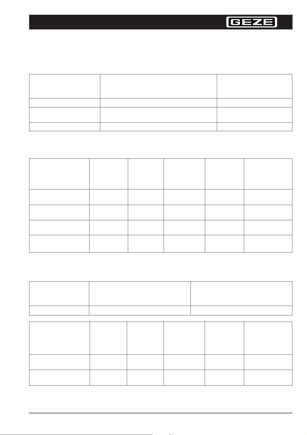
TSA 160 minimum and maximum leaf widths, hinge sizes
Single-leaf doors minimum maximum
door width door width
(mm) (mm)
TSA 160 pushing 69 0 1400
TSA 160 pulling 950 bei AV = 0 mm
89 0 bei AV = 60 mm *
TSA 160 Z 69 0 1400
*1) AV ... drive unit position
Double-leaf doors minimum maximum minimum minimum maximum
hinge size hinge size leaf width leaf width leaf width
2nd closing leaf 1st closing leaf
(mm) (mm) (mm)
*1)
*2)
1)
*2)
(mm)
1400
(mm)
1400
TSA 160 IS 1470 2800 690 400 1400
pushing
TSA 160 Z-IS 1470 2800 690 650 1400
pulling
TSA 160 IS/TS 1260 2800 690 400 1400
pushing
TSA 160 Z-IS/TS 1360 2800 690 650 1400
pulling
On smoke and fire-proof doors:
Single-leaf doors minimum maximum
door width door width
(mm) (mm)
TSA 160 F pushing 6 90 1400
Double-leaf doors minimum maximum minimum minimum maximum
hinge size hinge size leaf width leaf width leaf width
2nd closing leaf 1st closing leaf
(mm) (mm) (mm) *
2)
(mm) *
2)
(mm)
TSA 160 F-IS 1470 2800 690 400 1400
pushing
TSA 160 F-IS/TS 1260 2800 690 400 1400
pushing
*2)
The minimum hinge size must be observed!
13
Page 14
Planungsunterlage TSA160 Datei 84338PuTSA160_GB_200999_.p65
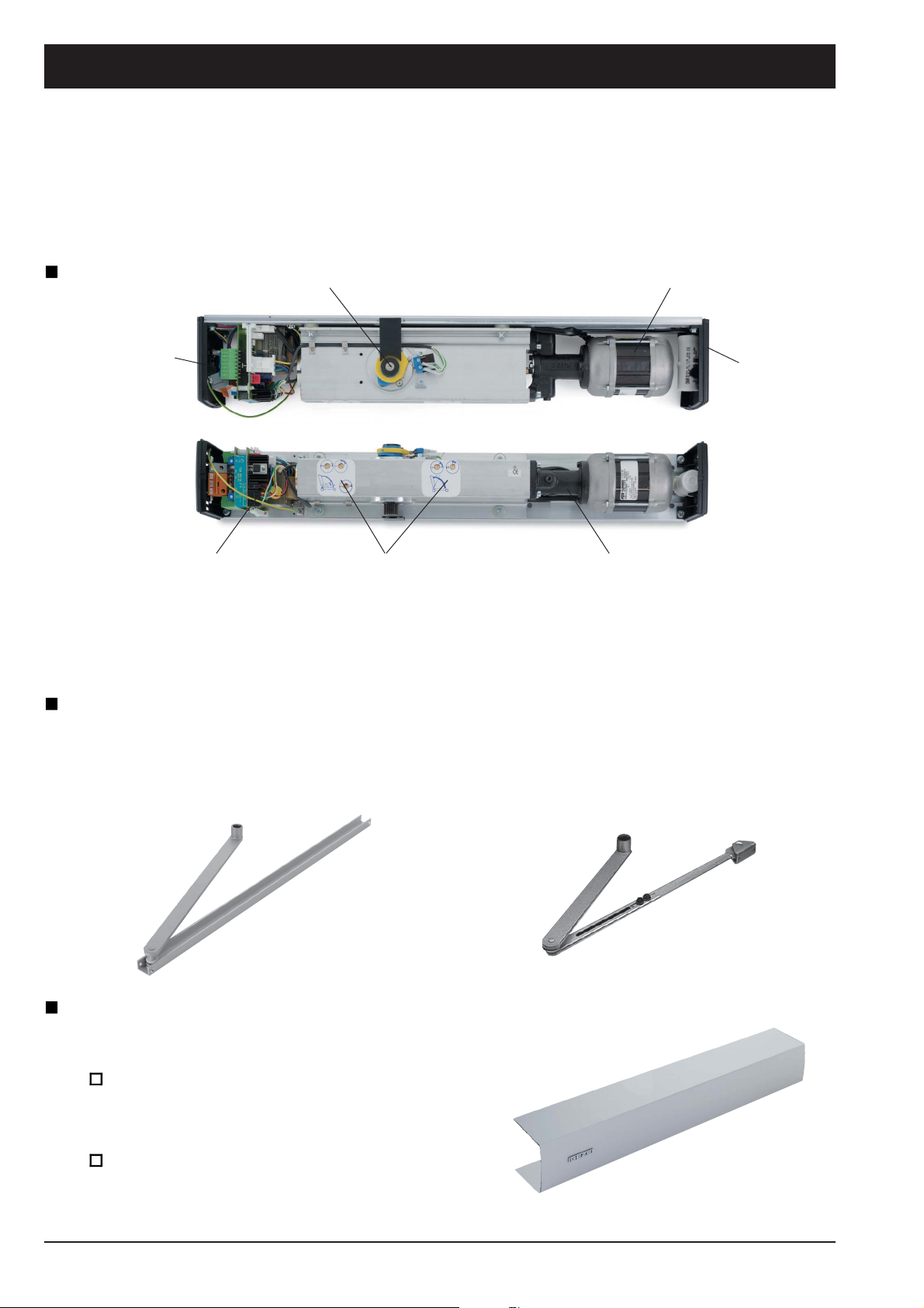
System description
The product is a modular system, consisting of:
Drive unit
Connecting
cable
Control with
potentiometer for
hold-open period,
actuation delay
Motor shaft Motor
Valve adjusting device for closing
damping, latching adjustment, opening
Guide rail or standard linkage
Side elements
Hydraulic pump
speed, opening damping
The possible use depends on the type of application. A pushing-version linkage is required for
smoke and fire-proof doors with TSA 160 drive (DIN 18263 part 4).
Linkage for reveal depth
- 0 ... 100 mm
- 100 ... 200 mm
- 200 ... 350 mm
Guide rail for
hinge side
pulling function
Linkage for opposite
hinge side
pushing function
Intermediate cover and add-on cover set
All necessary connections and ancilliary parts are aesthetically covered
Intermediate cover
for optical and functional connection
of two drives.
Add-on cover set
for single-leaf systems to extend to
full door width
14
Page 15
Planungsunterlage TSA160 Datei 84338PuTSA160_GB_200999_.p65
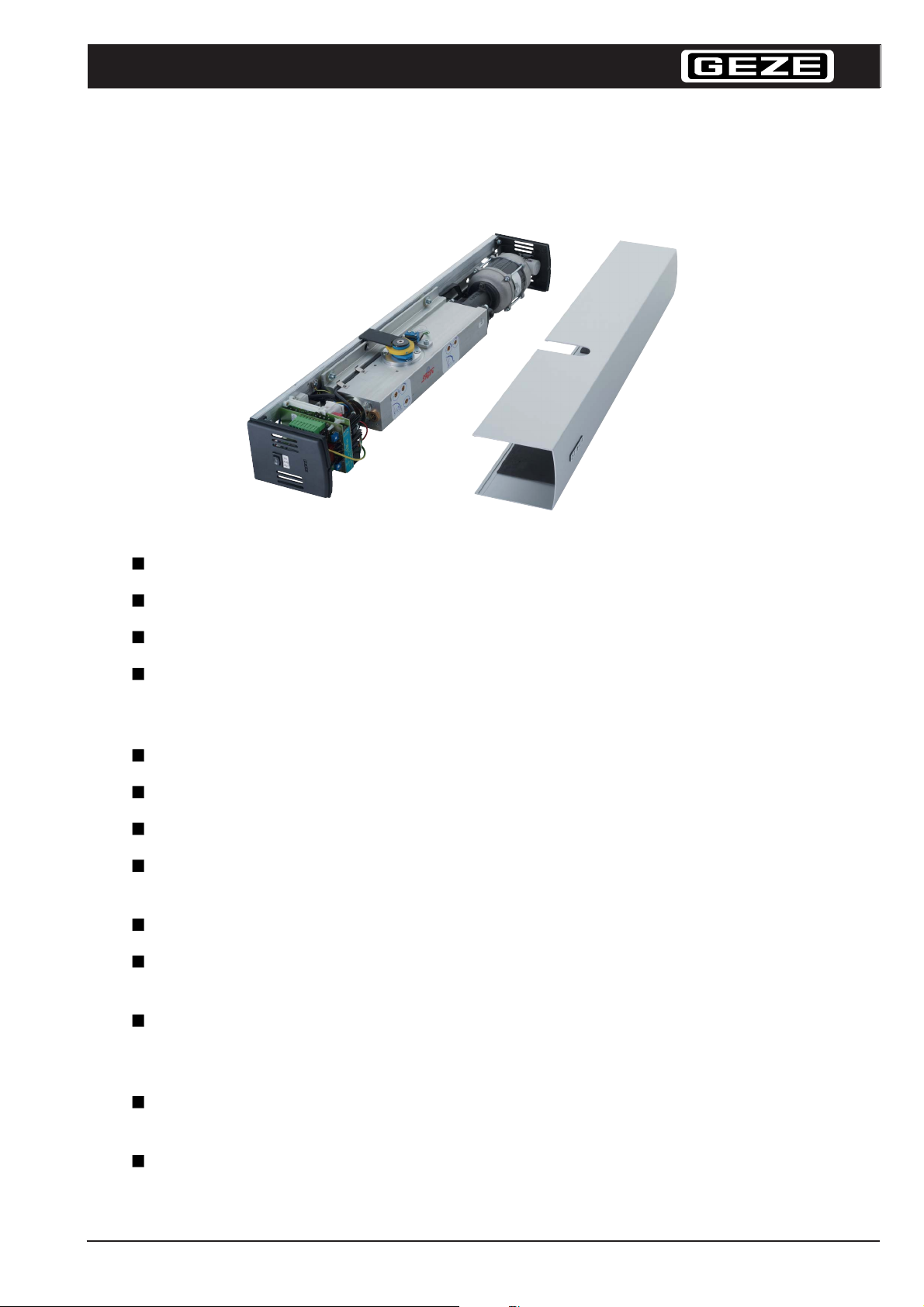
Technical Features
GEZE
Max. leaf width: 1400 mm
EN size: EN 3 to EN 6 (DIN size 2 ... 5)
Max. leaf weight: 250 kg
Dimensions: Length 690 mm
Height 100 mm (without spindle and lever)
Depth 120 mm (mounting plate plus 8 mm)
Closed position of door: Closing pressure by spring action
Power supply: 230 V AC, +10%/-14%, 50/60 Hz
Power consumption: 200 VA with 230 V AC
The motor is switched off as soon as the preset open position of the door is reached or
upon lapse of the preset motor running time.
Motor temperature control by integrated thermoswitch.
Power failure manual door closer function
hydraulically controlled closing
Integrated programme position II = automatic function
position I = permanently open
position 0 = off
Supply voltage for
peripheral appliances: 24 V DC, 800 mA
Weight of drive: ca. 13 kg
15
Page 16
Planungsunterlage TSA160 Datei 84338PuTSA160_GB_200999_.p65
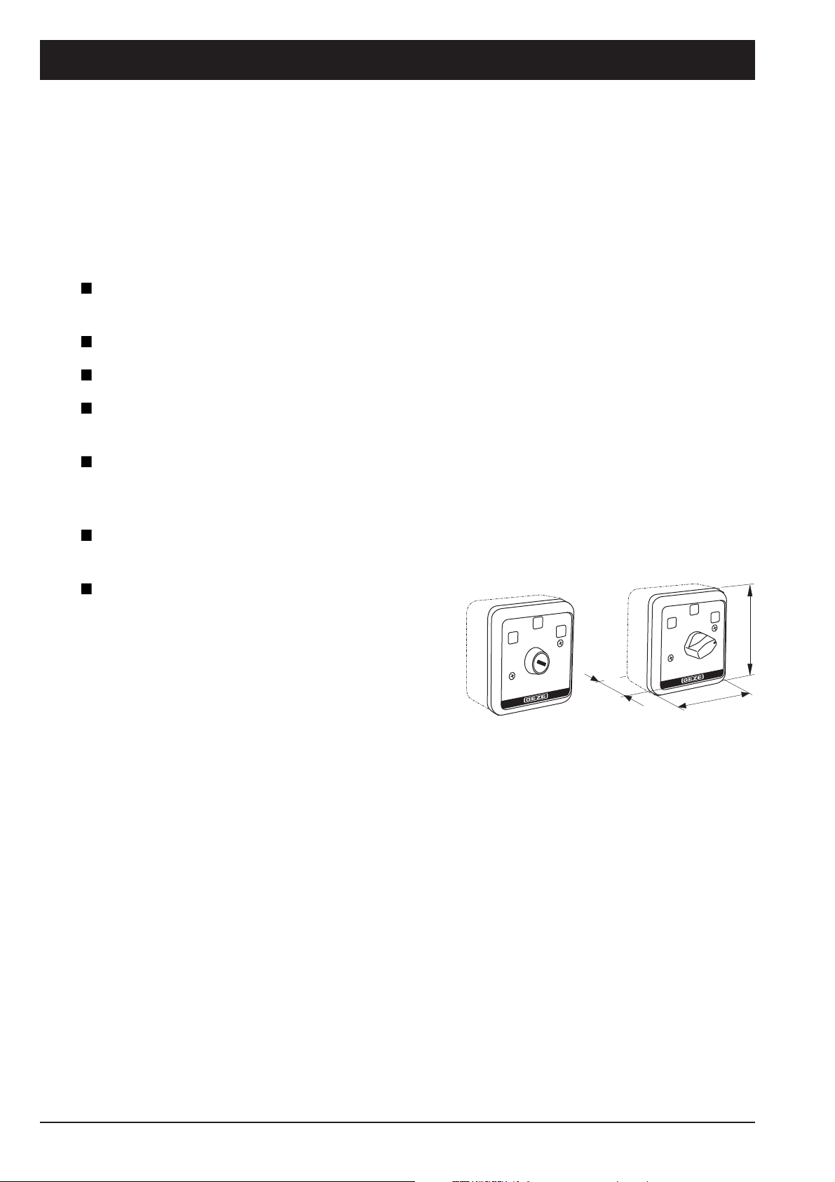
Connection possibilities for actuation elements
all known approach monitor elements can be connected, e.g.:
Radar movement detector for temperature-independent response,
even direction sensing
Infra-red movement detector
Passive infra-red movement detector
Pushbuttons of all kind, such as Code-card reader, key-operated switch, radio control
unit etc.
Door opener:
24 V DC open-circuit or closed-circuit principle *)
24 V AC open-circuit principle
Lock switch contact:
Must be installed in strikeplate if the door is locked manually
Internal programme switch
(external as an option) also available as
key-operated programme switch, with
3 positions:
- Off
- Automatic operation
- Permanently open
*) Explanation:
Open-circuit principle
Typical application: entrance door, compulsory for fire-proof doors
The locking process is made by the open-circuit principle, i.e. the door remains closed as long as the
lock is not live or actuated. The door is unlocked either by short-term actuation or permanent contact
(permanently open). In the case of power failure the door remains locked and can only be opened
mechanically via the cylinder or the door handle.
81
43
81
Available as flush or surface-mounted version
Typical application: RWS system
The door is locked as long as the system or the door opener is live. To open the door the circuit is
closed for a short time by willingly breaking the contact. The holding magnet of the door opener falls
off and the door is released.
Breaking of circuit means permanently open.
In the case of power failure the door is forcibly unlocked.
16
Closed-circuit principle
Page 17
Planungsunterlage TSA160 Datei 84338PuTSA160_GB_200999_.p65
Safety sensors
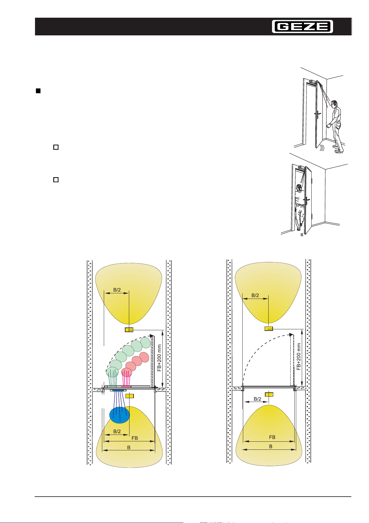
Field of application
Safety sensors are used to monitor the swiveling area of
automatic doors. The door stops moving as soon as one or
several persons step within the detection range of the sensor.
If the safety sensor “OPEN“ (SA) is used, the door
movement stops as soon as the sensor detects an obstable.
Wall recognition possible.
The safety sensor “CLOSE“ (SZ) actuates the drive of the
closing door and opens them again.
GEZE
safety sensors
AIR16
Incl. radar, on both sides and
SA = Safety sensor “OPEN“
SZ = Safety sensor “CLOSE“
Radar
Sensor
SA
Sensor
SZ
Radar
Incl. radar on both sides
Radar
Radar
FB = Width of the leaf
B = Width of the system
(possibly double-leaf)
17
Page 18
Planungsunterlage TSA160 Datei 84338PuTSA160_GB_200999_.p65
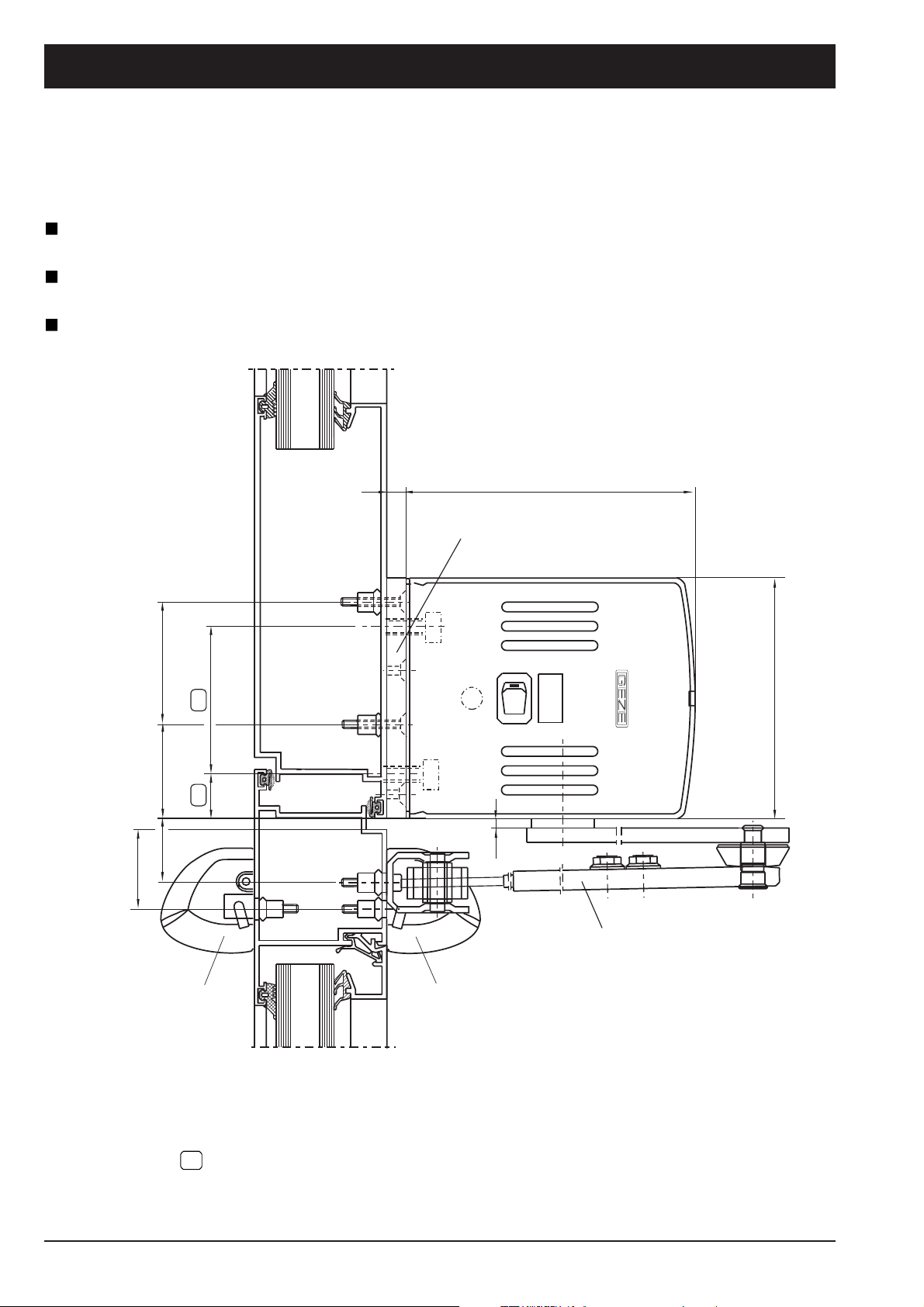
Side view and installation dimensions TSA 160
Opposite hinge side, pushing, incl. Mounting plate
For door widths 690 – 1400 mm
To be used vor TSA160Z Invers as well
8 120
33
51
39
31
54
23
Mounting plate L= 690 mm
DO
AUS
AUT
A*
Linkage, pushing
100
Safety sensor AIR 16
18
Actuation sensor AIR 16
*A
Spindle extension
optional 24, 30, 45 mm
Dimensions for direct mounting of drive
Further details see installation drawing No 70423-9-9920
(Swing door drive TSA 160 size 2-5 incl. safety and actuation sensor)
not illustrated above
(without scales)
Page 19
Planungsunterlage TSA160 Datei 84338PuTSA160_GB_200999_.p65
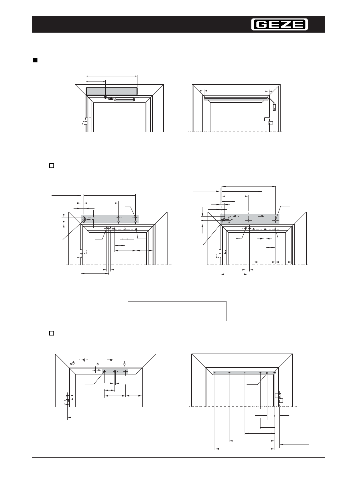
Dimensions of drive and sensors door DIN right pushing
690
260
GEZE
Drive and actuation sensor
opposite hinge side
Mounting dimensions drive door DIN right pushing
Dimensions for actuation sensor in [brackets]
Hinge centre
34
54
23
*)
50
335
420
M6
27
625
[
125
44
M6
]
[ø11]
[
260
[M5]
]
[a]
Hinge centre
14
Safety sensor hinge side
325
162.5
50
20
51
39
*)
11
335
487.5
M6
44
650
[ø11]
[260]
14
Blind rivet nut
M8
[M5]
[125]
[a]
Mounting dimensions for direct mounting Mounting dimensions
*) If cable entry is from the
rear make boring Ø 20
Doorwidth, [mm]
< 900
900 - 1400
Overalldimensions a [mm]
doorwidth - 700 (a
200
min
= 25)
when mounting plate is used
Mounting dimensions safety sensor (DIN right door)
Actuation sensor, dimensions in [brackets] Safety sensor, dimensions in [brackets]
[125]
[260]
[ø11]
[200]
For door widths > 900
mm make further
tappered boreholes at
intervals of 200 mm
(Ø10)
(114)
(400)
(600)
(800)
[M5]
Door hinge
axis
(50)
(200)
Door hinge
axis
19
Page 20
Planungsunterlage TSA160 Datei 84338PuTSA160_GB_200999_.p65
[mm]
Y
[mm]
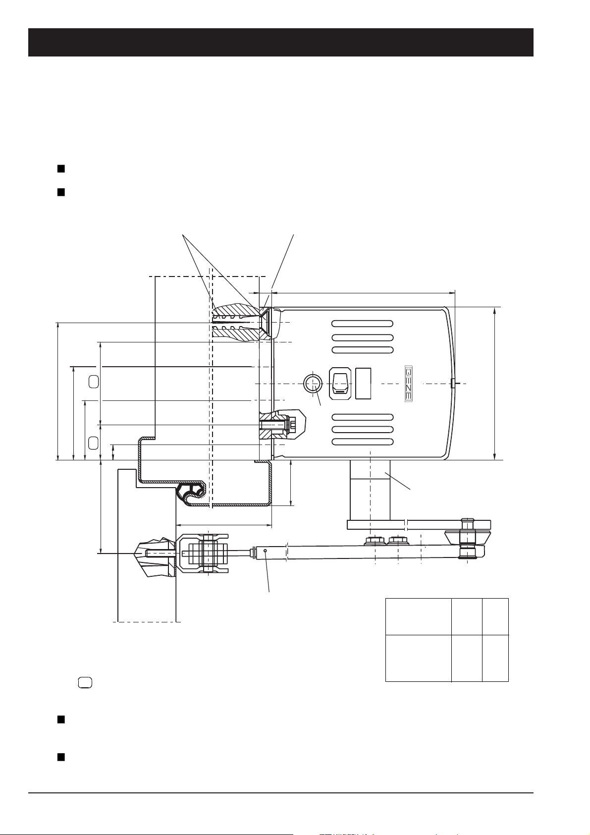
Side view and installation dimensions TSA 160 and TSA 160 F-IS
For double-leaf doors with integrated closing sequence control
Opposite hinge side, pushing, incl. mounting plate and steel frame
Door widths 690 – 1400 mm
90
61
min. 5 fixing points,
dowel S10
54
39
23
10
Mounting plate L= 690 mm
8
H
120
DO
AUS
AUT
Reset button
100
Spindle extension A*)
20
Y=31+A
(without scale)
X (max.350mm)
Linkage pushing
for soffit depth A
X = 0-100
100-200
200-350
*) Spindle
extension A
[mm]
-
24
30
45
Dimensions for direct mounting of drive
Further details see installation drawing No 70437-9-9910 (Swing door drive TSA 160F / F-IS)
2nd closing leaf = drive TSA 160 F-IS
1st closing leaf = drive TSA 160 or 1st closing leaf closer TS 160
2nd and 1st closing leaf incl. drive TSA 160 F
H
max
4
28
34
49
31
55
61
76
Page 21
Planungsunterlage TSA160 Datei 84338PuTSA160_GB_200999_.p65
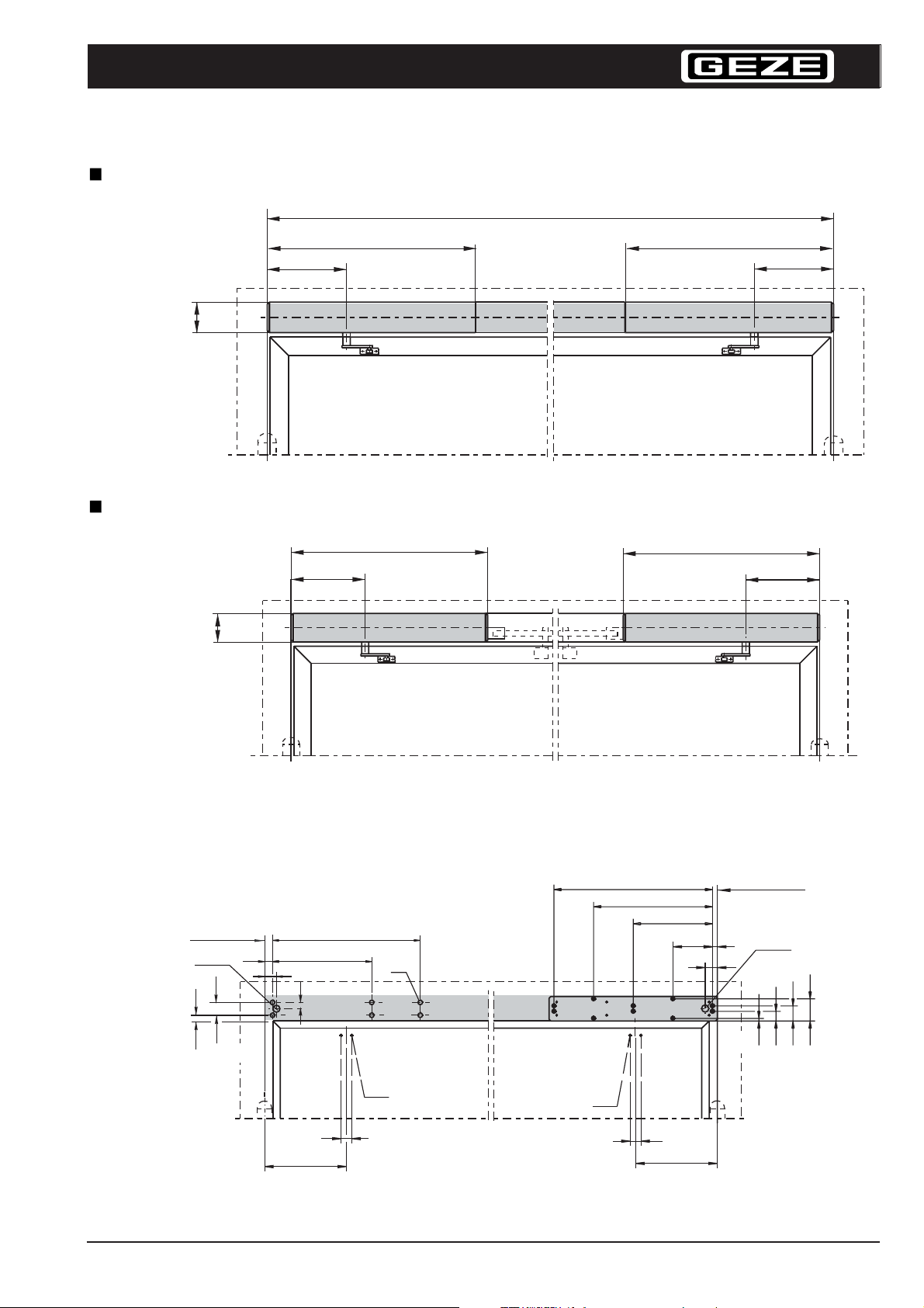
TSA 160 F-IS incl. integrated closing sequence control
B min = 1470
690 690
260
100
B max = 2800
Drive opposite hinge side
TSA 160 F incl. external closing sequence control
GEZE
260
690
260
100
Drive opposite hinge side
Mounting dimensions DIN right pushing
(Dimensions for direct fixing)
hinge centre
*1)
23
34
54
50
420
27
625
M6
690
260
Mounting dimensions DIN left pushing
(Dimensions incl. mounting plate)
650
487,5
325
162,5
hinge centre
20
50
10
*1)
39
61
90
M6
44
335
Mounting dimensions when mounting plate is used
*1) If cable entry is from the rear, make boring Ø 20
M6
44
335
21
Page 22
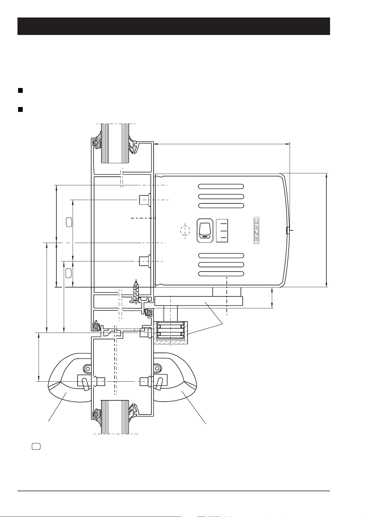
Planungsunterlage TSA160 Datei 84338PuTSA160_GB_200999_.p65
Side view and installation dimensions TSA 160 pulling
Hinge side, pulling, incl. safety and actuation sensor
For door widths 890 – 1400 mm
120
79
[(43)]
51*
39*
63
54
23
Automatic
OFF
const open
min
18,5
Lever and guide rail
incl. roller guide
100
Actuation sensor
AIR 16
Dimensions for direct mounting of drive
* Dimensions for mounting of drive with mounting plate (mounting plate not illustrated)
( ) dimensions for safety sensor, [ ] dimensions for actuation sensor
Further details see installation drawing No 70423-9-9921
(Swing door drive TSA 160 incl. safety and actuation sensor)
22
Safety sensor AIR 16
(without scale)
Page 23
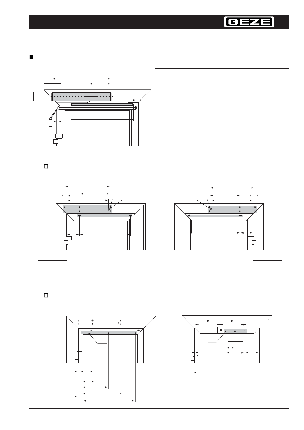
Planungsunterlage TSA160 Datei 84338PuTSA160_GB_200999_.p65
Drive DIN left pulling incl. guide rail and safety sensor
DIN right mirror image
Mounting of basic drive TSA 160 pulling
Min. leaf width: 890 mm ... 950 mm
AV
690
260
GEZE
incl.: AV 60 mm...AV 0 mm
100
14
Leaf width: FB 890 900 910 920 930 940 950
Door opening angle 110° 105° 103° 97° 93° 89° 85°
14
720
Guide rail
Drive unit position AV 60 50 40 30 20 10 0
Distance ± x 29 19 9 -1 -11 -21 -31
Distance y 176 186 196 206 216 226 236
Cable lead-through KD 5 80 590 600 610 620 630 640
Mounting dimensions for direct mounting,
Rebate DIN left pulling function
625
KD
420
M6
M5
708
x
+
-
y
*1)
Rebate DIN right pulling function
*1)
M5
M6
708
420
625
KD
+
-
x
y
Door hinge axis
-
+
*1) If cable supply is made from the rear, drill hole Ø 20
Mounting dimensions safety sensor in (brackets)
Safety sensor, dimensions in [brackets] Actuation sensor, dimensions in [brackets]
(Ø10)
(50)
Door hinge
axis
(200)
(114)
(400)
(600)
(800)
For widths of door >900 mm
drill additional tapped holes
at an interval of 200 mm
[M5]
Door hinge
axis
[125]
[260]
[ø11]
Door hinge axis
+
-
[200]
23
Page 24
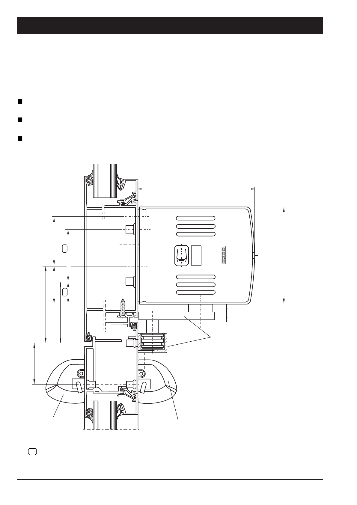
Planungsunterlage TSA160 Datei 84338PuTSA160_GB_200999_.p65
Side view and installation dimensions, 1- and 2- leafs
TSA 160 Z and TSA 160 Z-IS
Hinge side, pulling, incl. satefy and actuation sensor
For door widths 690 – 1400 mm
2nd closing leaf = drive TSA 160Z -IS
1st closing leaf = drive TSA 160 Z
120
43
79
51
39
63
54
23
DO
AUS
AUT
100
min. 18,5
Lever and guide rail, pulling
function with guide rollers
(without scale)
Actuation sensor
AIR16
Dimensions for direct mounting of drive
Further details see installation drawing No 70477-9-9804
(Swing door drive TSA 160 Z-IS incl. safety and actuation sensor)
24
Safety sensor
AIR16
Page 25
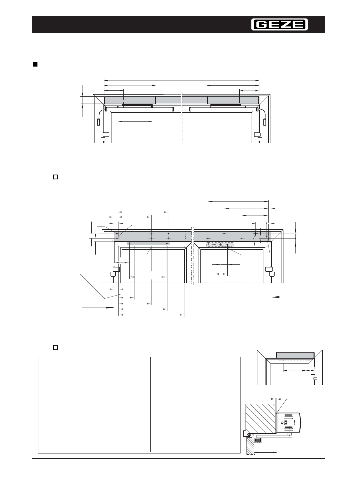
Planungsunterlage TSA160 Datei 84338PuTSA160_GB_200999_.p65
TSA 160 Z-IS incl. integrated closing sequence control
GEZE
690
260
100
465
guide rail
2nd closing leaf = drive TSA 160 Z-IS, hinge side
1st closing leaf = drive TSA 160 Z, hinge side
B min = 1470
B max = 2800
Mounting dimensions DIN left or right pulling:
...mounting plate ...direct mounting
625
54
M6
34
50
420
*2)
690
650
487,5
260
M6
325
162,5
11
20
50
51
For door widths > 900
mm make further
tappered boreholes at
intervals of 200 mm
Centre of hinge
guide rail pulling, for different soffit depths TSA 160 Z
Soffit depth “L“ from
– to (mm)
> 0 - 25
> 25 - 50
> 50 - 75
>75 - 100
> 100 - 125
>125 - 150
> 150 - 175
> 175 - 200
23
186
(50)
Mounting dimensions safety sensor in (brackets), hinge side
Mounting dimensions actuation sensor in [brackets] , opposite hinge side
Dimension “X“ (mm) for
guide rail with TSA160Z
186
192
203
215
229
244
262
280
(200)
(400)
(M5)
453
(600)
(800)
min. door width
(mm)
690
690
690
690
690
703
721
739
[160]
2*) If cable supply
is made from the rear,
drill hole Ø 20
Opening angle in
degrees
109 -113
113 - 115
115 - 110
110 - 105
105 - 100
100 - 97
97 - 95
95 - 90
[80]
[Ø10]
*2)
L
79
Centre of hinge
453
Mounting plate
8
x
25
Page 26
Planungsunterlage TSA160 Datei 84338PuTSA160_GB_200999_.p65
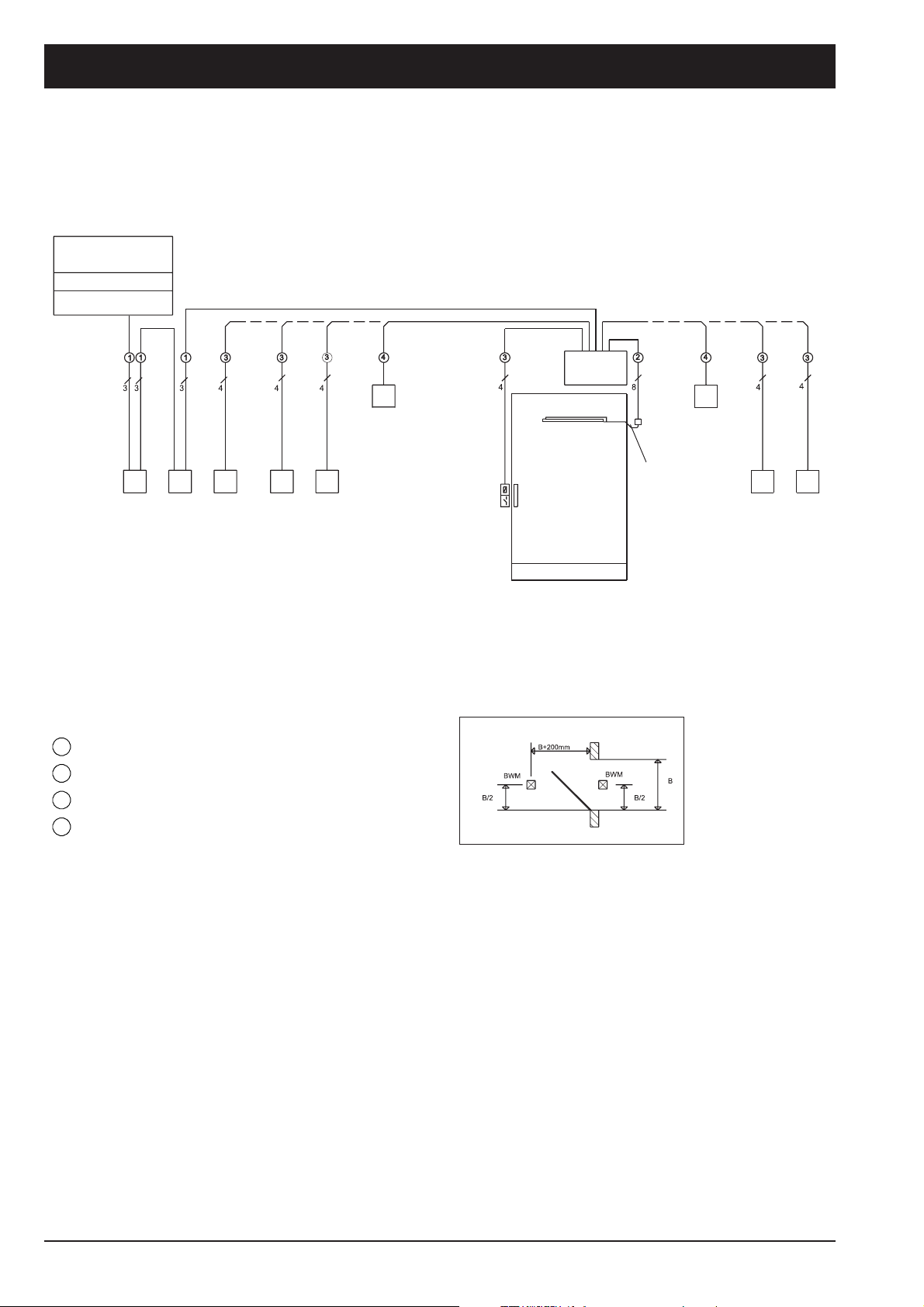
Cable plan
single-leaf door
Power supply line
230V/50Hz
Fuse 16 A
Connected load 200 W
and / or and / or
Cable outlet
for door drive
Door drive
TSA 160
Emergeny
Main
switch
cut-off
switch
Cross-sections of cable
= NYM-J 3x1,5 mm²
1
= J-Y(ST)Y 2x4x0,6 mm
2
= J-Y(ST)Y 2x2x0,6 mm
3
= Cable conduit with Ø16 mm
4
Key-
operated
switch
inside
Contactor
inside
Programme
switch
Movement
detector
inside
(see sketch
A)
Door opener
Lock switch contact
Positioning of the movement
detectors
Sketch A
Sensor strips
Movement
detector outside
(see sketch A)
8-pole door
transition cable
incl.connecting box
(provided by GEZE)
Contactor
outside
Key-
operated
switch
outside
Allow cable to protrude at least 1 m out of the wall
Note:
Any warranty and service agreements will
be rejected if GEZE products are combined
with third-party products.
For the installation and operation of the entire system the
guidelines (ZH1/494) for power-operated windows, doors
and gates (issued by the Association for Accident
Prevention and Industrial Medicine, 53757 Sankt Augustin)
have to be observed. In addition to this the mounting and
operating instructions as well as all other documents
refering to this product have to be observed.
26
In addition:
Wiring diagram 70423/9-9750
Cable plan single-leaf
TSA 160
230V 50Hz
Page 27
Planungsunterlage TSA160 Datei 84338PuTSA160_GB_200999_.p65
3113
1
3
3
5 5
4
2
2
3
4
3
4
43
4
3
1
2
8
3
4
4
3
4
RS5
RS5
GEZE
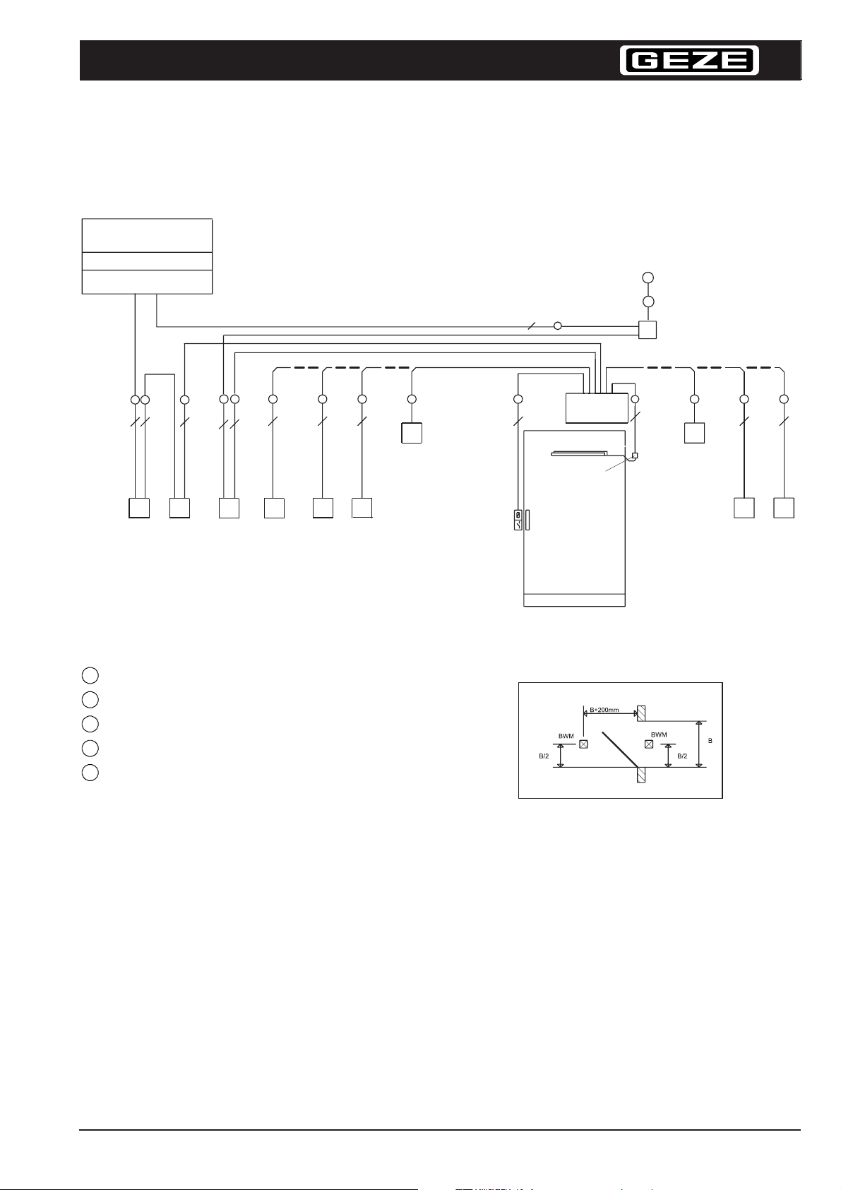
Cable plan
single-leaf smoke and fire-proof door, incl. central smoke control unit
Power supply line
230V/50Hz
Fuse 16 A
Connected load 200 W
and / or and / or
Cable outlet for
door drive
(acc. to
sketch A)
Ceiling mounted
alarm
Door drive
TSA 160F
RSZ 6
Main
switch
Emergeny
cut-off
switch
Breaker
contact
“close door”
Key-
operated
switch
inside
Contactor
inside
Programme
switch
Cross-sections of cable
= NYM-J 3x1,5 mm²
1
= J-Y(ST)Y 2x4x0,6 mm
2
= J-Y(ST)Y 2x2x0,6 mm
3
= Cable conduit with Ø16 mm
4
= J-Y(ST)Y 2x0,6 mm
5
Allow cable to protrude at least 1 m out of the wall
IMPORTANT:
The breaker contact must be installed in close
proximity to the door and must not be concealed by
the open door
Note:
Any warranty and service agreements will
be rejected if GEZE products are combined
with third-party products.
For the installation and operation of the entire system the guidelines
(ZH1/494) for power-operated windows, doors and gates (issued by
the Association for Accident Prevention and Industrial Medicine,
53757 Sankt Augustin) have to be observed. In addition to this the
mounting and operating instructions as well as all other documents
refering to this product have to be observed.
Movement
detector
inside
(see sketch
A)
Door opener
Lock switch contact
Sensor strips
8-pole door
transition cable
incl.connecting box
(provided by GEZE)
Movement
detector outside
(see sketch A)
Positioning of the movement
detectors
Sketch A
In addition:
Wiring diagram 70423/9-9750
Cable plan single-leaf
TSA 160 F incl. RSZ 6
230 V 50 Hz
Contactor
outside
Key-
operated
switch
outside
27
Page 28
Planungsunterlage TSA160 Datei 84338PuTSA160_GB_200999_.p65
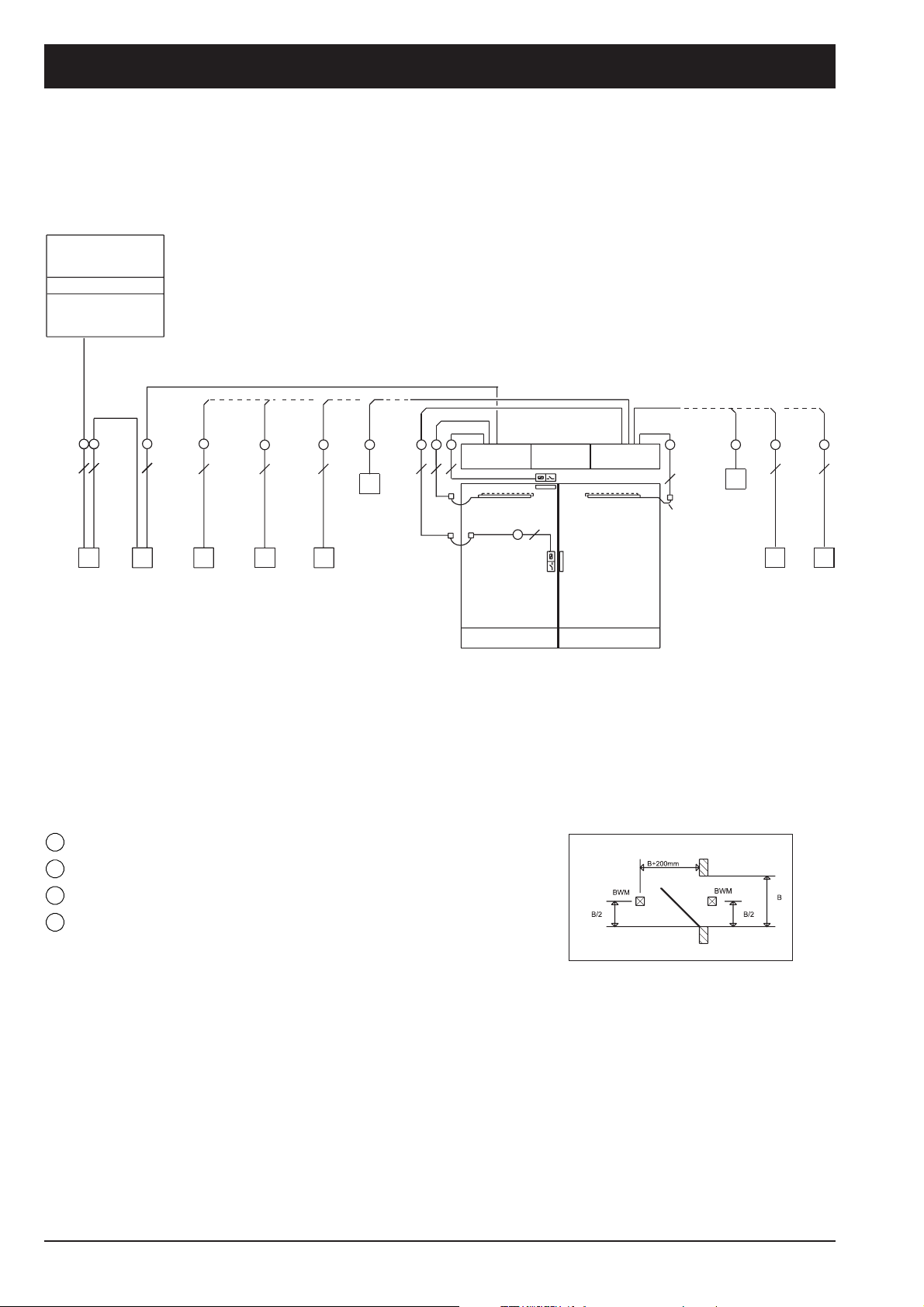
Cable plan
double-leaf door incl. integrated closer control
Power supply line
230V/50Hz
Fuse 16 A
Connected load
200 W
and / or
1
3
Main
switch
1
3
1
Emergeny
cut-off
switch
3
2
4
Programme
switch
3
4
Contactor
inside
3
4
Key-
operated
switch
inside
Cross-sections of cable
= NYM-J 3x1,5 mm²
1
= J-Y(ST)Y 2x4x0,6 mm
2
= J-Y(ST)Y 2x2x0,6 mm
3
= Cable conduit with Ø16 mm
4
Allow cable to protrude at least 1 m out of the wal
4
Movement
detector
inside
(see sketch
A)
Cable outlet for
door drive
34343
Door drive 2
4
TSA 160
Sensor strips
*1)
*2)
Lock switch contact
2nd closing leaf
*1) 8-pole door transition cable incl.connecting box
(provided by GEZE)
*2) Door transition cable/provided by customer
3
Door opener
Intermediate
cover kit
4
and / or
Door drive 1
TSA 160 -IS
Sensor strips
1st closing leaf
2
8
*1)
4
Movement
detector outside
(see sketch A)
Contactor
Positioning of the movement
detectors
Sketch A
3
outside
3
Key-
operated
switch
outside
44
Note:
Any warranty and service agreements will
be rejected if GEZE products are combined
with third-party products.
For the installation and operation of the entire system the guidelines
(ZH1/494) for power-operated windows, doors and gates (issued by
the Association for Accident Prevention and Industrial Medicine,
53757 Sankt Augustin) have to be observed. In addition to this the
mounting and operating instructions as well as all other documents
refering to this product have to be observed.
28
In addition:
Wiring diagram 70423/9-9750
Cable plan double-leaf
TSA 160 - IS
230 V 50 Hz
Page 29
Planungsunterlage TSA160 Datei 84338PuTSA160_GB_200999_.p65
3
32
32
1
1
155
1
3
44
8
24
3
3
3
4
3
4
3
4
34343
4
4
*1)
4
3
*1)
*2)
RS5
RS5
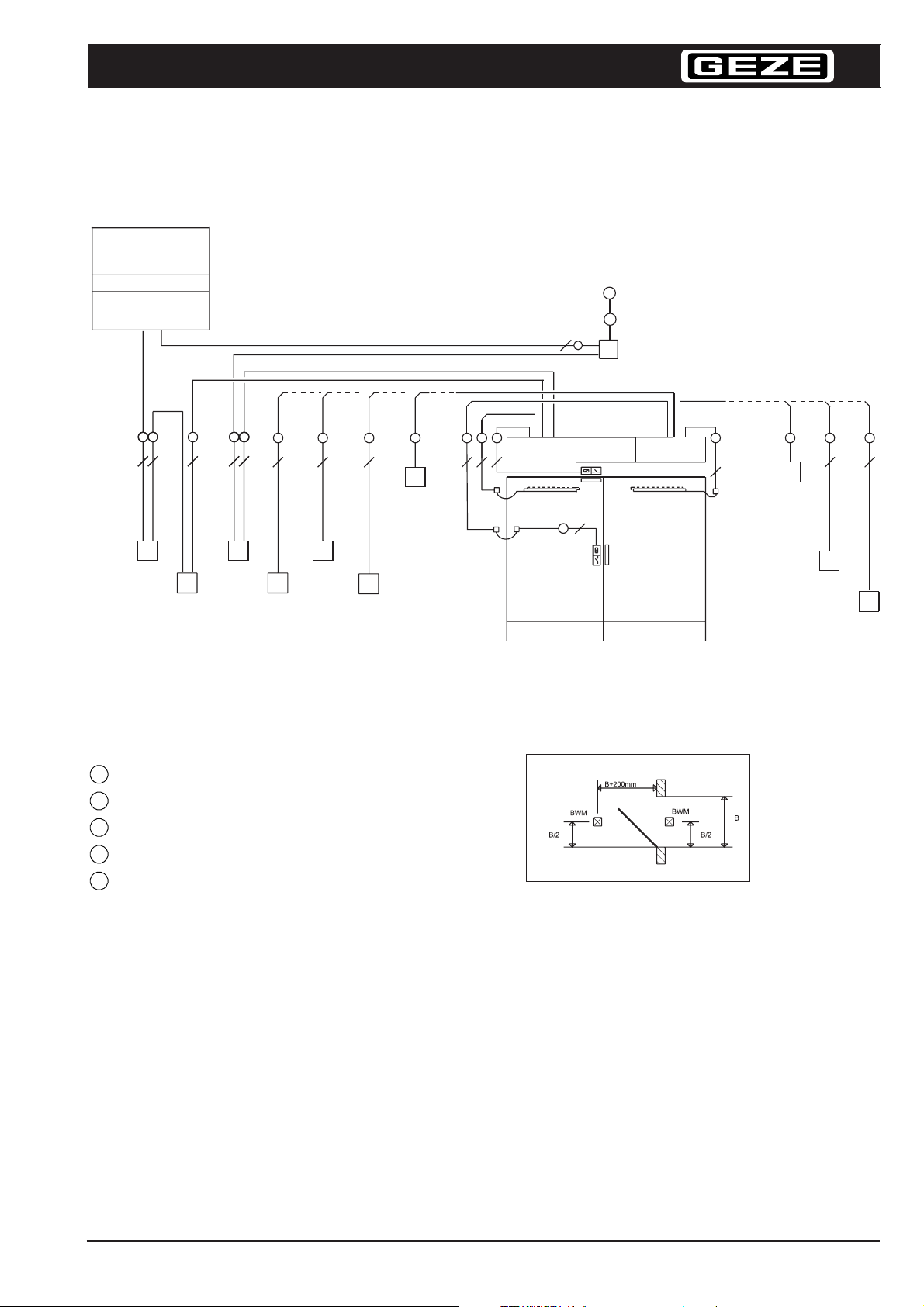
Cable plan
double-leaf door incl. central smoke control unit
Power supply line
230V/50Hz
Fuse 16 A
Connected load
2 x 200 W
Ceiling mounted
GEZE
alarm
RSZ 6
and / or
Main
switch
Emergeny
cut-off
switch
Breaker
contact
“close door”
Contactor
inside
Programme
switch
Key-
operated
switch
inside
Cross-sections of cable
= NYM-J 3x1,5 mm²
1
= J-Y(ST)Y 2x4x0,6 mm
2
= J-Y(ST)Y 2x2x0,6 mm
3
= Cable conduit with Ø16 mm
4
= J-Y(ST)Y 2x0,6 mm
5
Allow cable to protrude at least 1 m out of the wall
Movement
detector
inside
(see sketch
A)
Cable outlet for door drive
Door opener
(acc. to drawing)
Intermediate
cover kit
1st closing leaf
Door drive
TSA 160 F-IS
Sensor strips
Door drive
TSA 160 F
Sensor strips
Lock switch contact
2nd closing leaf
*1) 8-pole door transition cable incl.connecting box
(provided by GEZE)
2*)Door transition cable/provided by customer
Positioning of the
movement detectors
Sketch A
In addition:
and / or
Movement
detector outside
(see sketch A)
Contactor
outside
Key-
operated
switch
outside
IMPORTANT:
The breaker contact must be installed in close
proximity to the door und must not be concealed by the
open door
Note:
Any warranty and service agreements will
be rejected if GEZE products are combined
with third-party products.
For the installation and operation of the entire system the guidelines
(ZH1/494) for power-operated windows, doors and gates (issued by
the Association for Accident Prevention and Industrial Medicine,
53757 Sankt Augustin) have to be observed. In addition to this the
mounting and operating instructions as well as all other documents
refering to this product have to be observed.
Wiring diagram 70423/9-9750
Cable plan double-leaf
TSA 160F -IS incl. RSZ 6
230 V 50 Hz
29
Page 30
Planungsunterlage TSA160 Datei 84338PuTSA160_GB_200999_.p65
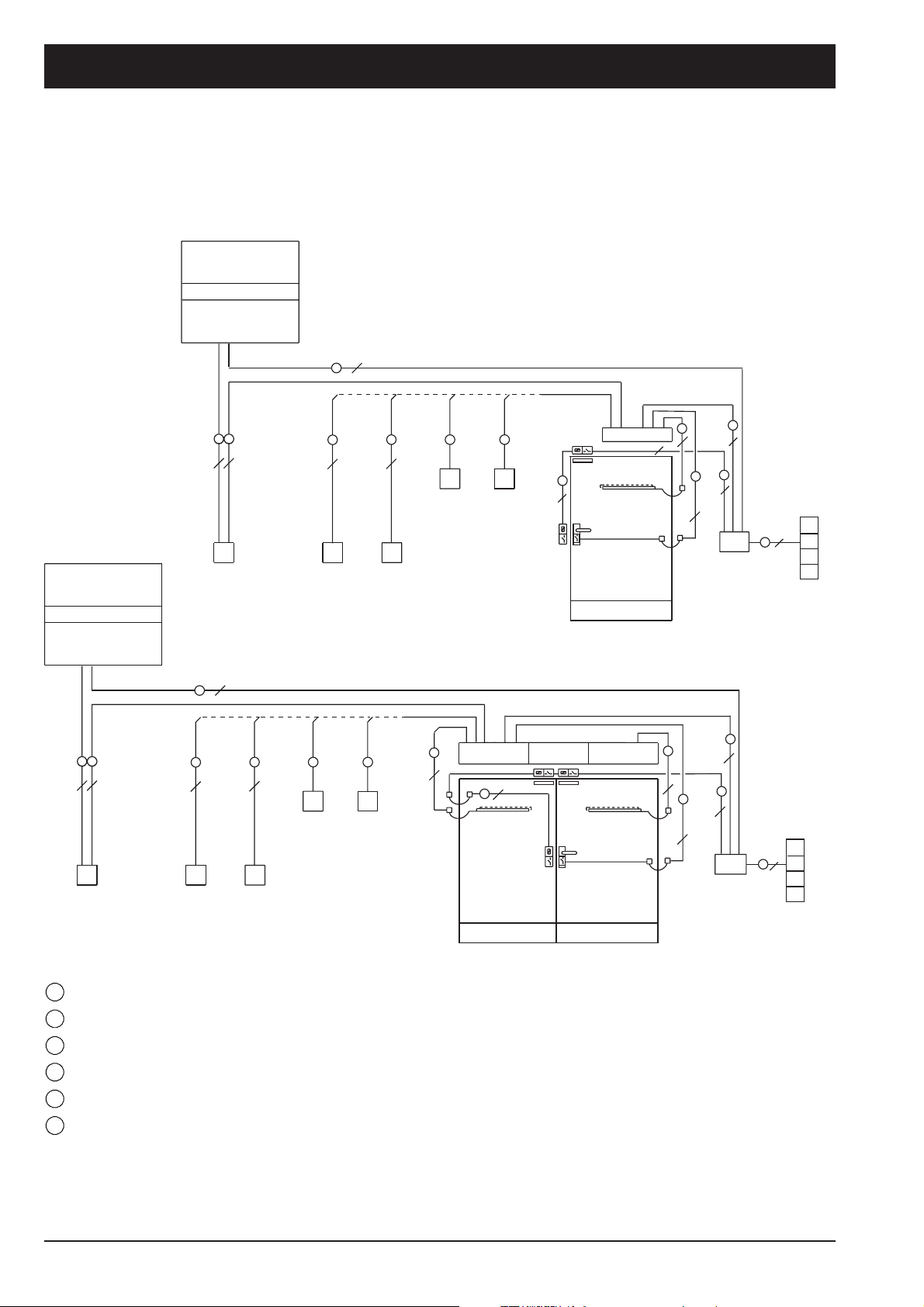
Cable plan single and double-leaf
with door control unit TZ 220
Power supply line
230V/50Hz
Fuse 16 A
Connected load
2 x 200 W
3
1
and / or
Power supply line
230V/50Hz
Fuse 16 A
Connected load
2 x 200 W
1
1
3
3
Main
switch
1
3
4
Contactor
inside
1
3
Main
switch
3
1
3
Contactor
outside
8
5
2
Terminal box
Terminal box
2
8
2
8
8
2
TZ 220 KL
2
8
2
8
8
2
TSA 160 Inverse
TO+FK
FS
Sensor strips
2
8
Rotary switch contact
Doordrive
TSA 160 Inverse
TO+FK
FS
Sensor strips
Rotary switch contact
Contactor
4
Movement
detector
outside
3
4
outside
3
4
Contactor
inside
and / or
3
4
4
Movement
detector
inside
4
Movement
detector
inside
6
6
4
*2
*1
4
Movement
detector
outside
Door opener with
latch contact
Doordrive
TSA 160 Inverse
TO+FK
8
2
Sensor strips
Door opener with
latch contact
Intermediate
cover kit
FS
2
4
*1
*2
6
8
5
*1
2
*2
TZ 220 KL
2nd closing leaf 1st closing leaf
Cross-sections of cable
= NYM-J 3x1,5 mm²
1
= J-Y(ST)Y 2x4x0,6 mm
2
= J-Y(ST)Y 2x2x0,6 mm
3
= Cable conduit with Ø16 mm
4
= LiYY(ST)Y 2x0,14 mm²
5
= LiYY 4x2x0,25 mm²
6
Allow cable to protrude at least 1 m out of the wall
30
*1) 8-pole door transition cable incl.connecting box
(provided by GEZE)
2*)
Door transition cable/provided by customer
In addition:
Wiring diagram TSA 160 Invers: 70423/9-9758
Wiring diagram TZ 220: 21208-9-0952
Wiring diagram TSA 160 Invers
with TZ 220 single and double-leaf
320 V 50 Hz
Page 31
Planungsunterlage TSA160 Datei 84338PuTSA160_GB_200999_.p65
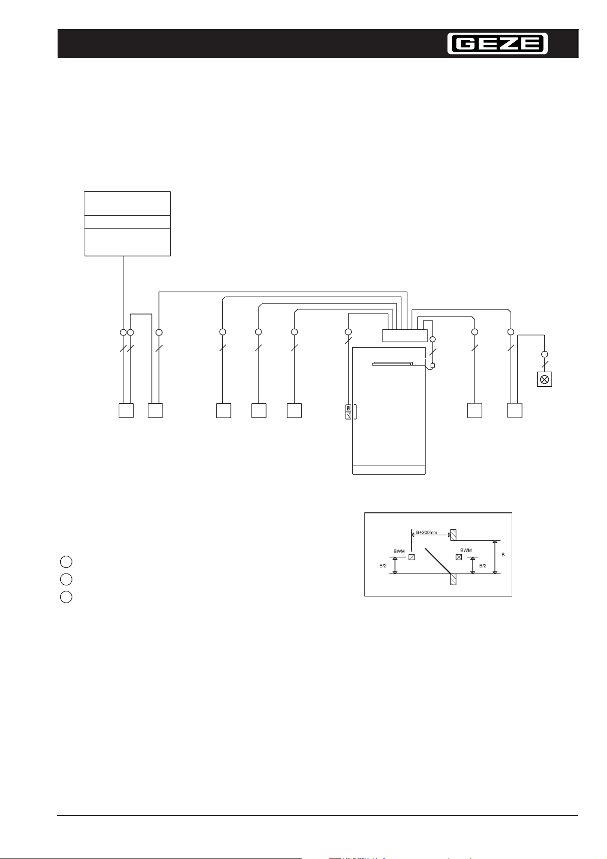
Cable plan
TSA 160 WC-compartment
for the handicapped
Power supply line
230V/50Hz
Fuse 16 A
Connected load
2 x 200 W
GEZE
3
4
Key-operated
switch,
exterior
4
Contactor,
exterior
3113
Main
switch
1
3
Emergeny
cut-off
switch
Cross-sections of cable
= NYM-J 3x1,5 mm²
1
= J-Y(ST)Y 2x4x0,6 mm
2
= J-Y(ST)Y 2x2x0,6 mm
3
Allow cable to protrude at least 1 m out of the wall
3
3
4
Programme
switch
(lockable),
exterior
3
4
Sensor strips
Door opener,
lock switch
contact
TSA160
2
8
*1
3
4
Contactor,
interior
3
4
“OCCUPIED“
change-over
switch with
lamp 24 V/80
mA, interior
3
4
Lamp
“OCCUPIED“
24 V/80 mA,
exterior
Positioning of the movement detectors
Sketch A
IMPORTANT:
The breaker contact must be installed in close
proximity to the door and must not be concealed by
the open door
Note:
Any warranty and service agreements will
be rejected if GEZE products are combined
with third-party products.
In addition:
Wiring diagram 70423/9-9750
Auxiliary wiring diagram WC-control70712/9-961
Wiring diagram TSA 160 WC-
compartment for the handicapped
single-leaf
230 V 50 Hz
31
Page 32
Planungsunterlage TSA160 Datei 84338PuTSA160_GB_200999_.p65
GEZE GmbH
P.O. Box 1363
71226 Leonberg
Germany
GEZE GmbH
Reinhold-Vöster-Str. 21-29
71229 Leonberg
Germany
Tel. +49 (0) 7152 - 203 - 0
Fax +49 (0) 7152 - 203 - 310
GEZE Online:
www.geze.com
GEZE Branches
Germany
GEZE GmbH
Niederlassung Nord/Ost
Bühringstr. 8
13086 Berlin (Weissensee)
Tel. +49 (0) 30 - 47 89 90 - 0
Fax +49 (0) 30 - 47 89 90 - 17
E-Mail: [email protected]
GEZE GmbH
Niederlassung West
Nordsternstraße 65
45329 Essen
Tel. +49 (0) 2 01 - 8 30 82-0
Fax +49 (0) 2 01 - 8 30 82-20
E-Mail: [email protected]
GEZE GmbH
Niederlassung Mitte
Adenauerallee 2
61440 Oberursel
Tel. +49 (0) 6171 - 6 36 10 - 0
Fax +49 (0) 6171 - 6 36 10 - 1
E-Mail: [email protected]
GEZE GmbH
Niederlassung Süd
Reinhold-Vöster-Straße 21-29
71229 Leonberg
Tel. +49 (0) 7152 - 203 - 5 94
Fax +49 (0) 7152 - 203 - 4 38
E-Mail: [email protected]
Subsidiaries
Germany
GEZE Sonderkonstruktionen
GmbH
Planken 1
97944 Boxberg-Schweigern
Tel. +49 (0) 79 30- 92 94-0
Fax +49 (0) 7930- 92 94-10
E-mail: [email protected]
GEZE SERVICE GmbH
Reinhold-Vöster-Str. 25
71229 Leonberg
Te. +49 (0) 7152- 92 33-0
Fax +49 (0) 7152- 92 33-60
E-Mail: [email protected]
Asia
GEZE Asia Pacific Ltd.
Unit 630, Level 6, Tower 2
Grand Central Plaza
138 Shatin Rural Committee Road
Shatin, New Territories
Hong Kong
Tel. +852 (0)23 75 73 82
Fax +852 (0)23 75 79 36
E-Mail: [email protected]
GEZE Industries
(Tianjin) Co., Ltd.
Shuangchenzhong Road
Beichen Economic Development
Area (BEDA)
Tianjin 300400, P.R. China
Tel. +86 (0)22-26 97 39 95-0
Fax +86 (0)22-26 97 27 02
E-Mail: [email protected]
GEZE Industries
(Tianjin) Co., Ltd.
Branch Office Shanghai
Dynasty Business Center
Room 401-402
No. 457 WuRuMuQi North Road
200040 Shanghai, P.R. China
Tel. +86 (0)21 52 34 09-60/-61/-62
Fax +86 (0)21 52 34 09-63
E-Mail: [email protected]
GEZE Industries
(Tianjin) Co., Ltd.
Branch Office Guangzhou
Room 1113 Jie Tai Plaza
218-222 Zhong Shan Liu Road
510180 Guangzhou, P.R. China
Tel. +86 (0)20 81 32 07 02
Fax +86 (0)20 81 32 07 05
E-Mail: [email protected]
GEZE Industries
(Tianjin) Co., Ltd.
Branch Office Beijing
The Grand Pacific Building
B Tower Room 201
8A, Guanghua Road
Chaoyang District
100026 Beijing, P.R. China
Tel. +86 (0)10 65 81 57-32/-42/-43
Fax +86 (0)10 65 81 57-33
E-Mail: [email protected]
GEZE Asia Sales Ltd.
No. 88-1-408, East Road
Free Trade Zone of Tianjin Port
Tianjin, P.R. China
Tel. +86 (0)22-26 97 39 95-0
Fax +86 (0)22 26 97 27 02
E-mail: [email protected]
GEZE Asia Pacific Ltd.
Branch Office Singapore
Level 4
177 Kaki Bukit Avenue 1
Shun Li Industrial Park
Singapore 416023
Tel. +65 6846 1338
Fax +65 6846 9353
E-mail: [email protected]
Middle East
U.A.E
GEZE Middle East
P.O. Box 17903
Jebel Ali Free Zone
Dubai, U.A.E.
Tel. +971 (0)4 88 33 112
Fax +971 (0)4 88 33 240
E-Mail:[email protected]
Europe
France
GEZE France S.A.R.L.
ZAC de l’Orme Rond
RN 19
77170 Servon
Tel. +33 1 60 62 60 70
Fax +33 1 60 62 60 71
E-mail: [email protected]
Great Britain
GEZE UK Ltd.
Blenheim Way
Fradley Park
Lichfield
Staffordshire, WS13 8SX
Tel. +44 (0) 1543-443000
Fax +44 (0) 1543-443001
E-Mail: [email protected]
Italy
GEZE Italia Srl
Via Giotto 4
20040 Cambiago (Mi)
Tel. +39 (0)02 95 06 95-11
Fax +39 (0)02 95 06 95-33
E-Mail: [email protected]
GEZE Engineering Roma Srl
Via Lucrezia Romana 91
00178 Roma
Tel. +39 (0)06 72 65 31 1
Fax +39 (0)06 72 65 31 36
E-Mail: [email protected]
GEZE Engineering Bari Srl
Via Treviso 58
70022 Altamura (Bari)
Tel. +39-(0)80-31 15 21 9
Fax +39-(0)80-31 64 56 1
E-Mail: [email protected]
Benelux
GEZE Benelux B.V.
Industrieterrein, Kapelbeemd,
Leemkuil 1,
5626 EA Eindhoven
Tel. +31- 40 26 29 08 0
Fax +31 - 40 26 29 08 5
E-Mail: [email protected]
Austria
GEZE Austria GmbH
Mayrwiesstraße 12
5300 Hallwang b. Salzburg
Tel. +43 (0)662 66 31 42
Fax +43 (0)662 66 31 42-15
E-Mail: [email protected]
Poland
GEZE Polska Sp.z o.o.
ul. Annopol 3 (Zeran Park)
03-236 Warszawa
Tel. +48 (0) 22-814 22 11
Fax +48 (0) 22-614 25 40
E-mail: [email protected]
Schwitzerland
GEZE Schweiz AG
Bodenackerstr. 79
4657 Dulliken
Tel. +41 (0) 62-285 54 00
Fax +41 (0) 62-285 54 01
E-Mail: [email protected]
Spain
GEZE Iberia S.R.L.
Pol. Ind.El Pla
C/ Comerc, 2-22, Nave 12
08980 Sant Feliu de Llobregat
(Barcelona)
Tel. +34 (0)9-02 19 40 36
Fax +34 (0)9-02 19 40 35
E-Mail: [email protected]
Skandinavia
Sweden
GEZE Scandinavia AB
Mallslingan 10
Box 7060
18711 Täby
Tel. +46 (0) 8 - 732 34 - 00
Fax +46 (0) 8 - 732 34 - 99
E-Mail: [email protected]
Norway
GEZE Scandinavia AB avd. Norge
Postboks 63
2081 Eidsvoll
Tel. +47 (0)639 572 00
Fax +47 (0)639 571 73
E-Mail: [email protected]
Finnland
GEZE Finland
Branch office of GEZE Scandinavia AB
Postbox 20
158 71 Hollola
Tel. +385 (0)10-400 5100
Fax +385 (0)10-400 5120
E-Mail: [email protected]
GEZE SERVICE GmbH
Niederlassung Berlin
Bühringstraße 8
13086 Berlin (Weissensee)
Tel. +49 (0) 30- 47 02 17 30
Fax +49 (0) 30- 47 02 17 33
Your attention is drawn to the 'product liability
law' defined liability to the manufacturer for this
produts which are contained in the main
catalogue (product information, usage, misuses,
product activity, product maintenance, the duty
to inform and the duty to instruct). Non
compliance with these conditions relieves the
manufacturer from any liability.
GEZE Representative:
Mat.-Nr. 084338 / Vers. 01 / 1003 / Printed in Germany - Subject to change without notice
32
 Loading...