

Page 1

U.S.
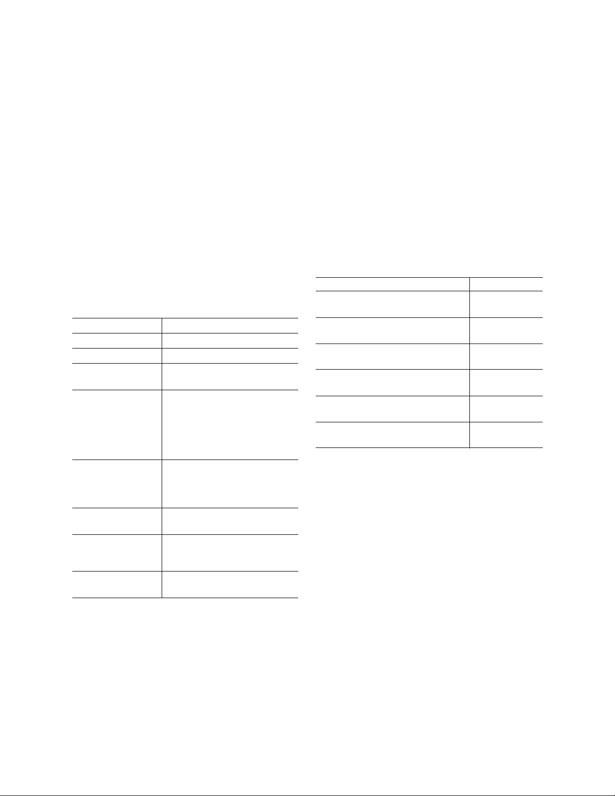
front view
side
view
1.75
[44.5mm]
1.0
[25.4mm]
4.20
[106.7mm]
T 888 536 3573
F 561 998 6224
Asia
T 65 6424 7932
F 65 6424 7978
Australia
T 61 3 9239 1200
F 61 3 9239 1299
Canada
T 800 267 6317
F 613 737 5517
EMEA
T 48 58 326 22 40
F 48 58 326 22 41
Latin America
T 503 589 8614
F 561 994 6572
www.utcfireandsecurity.com
© 2012 UTC Fire & Security. All rights reserved.
UTC Fire & Security, 9 Farm Springs Road,
Farmington, CT 06034-4065, USA
Transition Series
T-200 Model Reader
Description
The T-200 Transition™ Series card reader is a card serial
number reader compatible with the following 13.56 mHz
technologies:
Vicinity (ISO 15693) HID iCLASS® Serial Number
®
Infineon my-d
Philips I-Code Serial Number
Proximity (ISO14443) DESFire
MIFARE
Serial Number
®
Serial Number
®
Serial Number
Mounting the reader
1. Find a suitable mounting position on the door frame
or wall.
2. Drill two vertical mounting holes 2.25” (57.2 mm)
apart on the mounting surface of the door frame or
wall.
Figure 1. Dimensions
3. Drill one 1.00” (25.4 mm) diameter hole in wall for the
pigtail wire connection.
4. Follow the Cable Connection Chart to connect the
reader to the field panel and external door
equipment.
5. Mount the base plate to the wall using the supplied
screws.
6. Hook the top of the reader case to the top of the base
plate and press into place.
Figure 2. Aligning top cover, reader case, and base plate.
7. Install the supplied screw in the base of the reader.
8. Snap the cover on the top of the case.
Connecting the cable
1. The readers are supplied with a 8-conductor cable
pigtail with drain wire. Connect the pigtail to the host
panel. Use the Cable Connection Chart (below) to
correctly match the color of each wire.
Color Signal
Black Ground
Blue Beeper
Brown Red LED Control
Green Data 0
Orange Green LED Control
Red 5 to 16 VDC
White Data 1
Drain Shield Ground
2. Use a DC power source between 5-16 VDC.
3. Connect reader’s drain wire to the cable shield.
Connect shield wires at the field panel.
Page 2
Testing the reader
1. Power up the reader. Verify the power-on self
test LED/beep sequence:
- green LED flashes; two short beeps
- yellow LED flashes; three short beeps
- red LED flashes
- yellow LED flashes
2. Verify the yellow LED is on continuously
indicating the reader is ready.
3. Present a badge that has been properly
enrolled in the system. Verify the green LED
lights and a short beep is heard.
Removing the cover
To remove the cover, squeeze the sides of the top
cover and pull to release the cover.
Specifications
Colors Black, Charcoal,
Power supply Linear DC recommended
Voltage range 5 - 16 VDC
Temperature
a
range
Cable distance to
b
panel
Read Range
(Distances may
vary depending on
environment.)
Wiegand output - Mifare 4002 (40-bit)
Regulatory
approvals and
standards
ISO Standards Mifare ISO 14443A
UL evaluation for UL Listed Installations:
a. -25°F to 125°F (32°C to 52°C)
b. 500 ft. (152.4 m) max. @ 22 awg 12 VDC
c. Vicinity: up to 3.0" (7.62 cm)
c
200 ft. (60.96 m) max. @ 22 awg 5 VDC
-31°F to 149°F
(-35°C to 65°C)
200 ft. (60.96 m) max.
@ 22 awg 12 VDC
300 ft. (91.44 m) max.
@ 20 awg 12 VDC
500 ft. (152.4 m) max.
@ 18 awg 12 VDC
- Mifare:
up to 1.0" (2.54 cm)
Ultralight cards not supported
- Vicinity: up to 3.5" (8.89 cm)
- Vicinity 5502 (55-bit)
UL 294, CE, and FCC (part 15)
Vicinity ISO 15693
The voltage specification for this reader is 5-16
VDC, although 12 VDC or greater is recommended
for better performance and cable run distances.
Light gray
The recommended cable gauge is 18-gauge to 22gauge. Check with the cable supplier to determine
the best choice for the application and installation
distance.
FCC compliance
The FCC requires the following statement: This
reader uses radio frequency energy, has been
tested, and complies with the limits of FCC testing.
Changes, modifications, or disregard of proper
installation and instructions not expressly approved
by UTC Fire & Security are strictly prohibited by the
FCC and could void the user’s authority to operate
the equipment.
Ordering information
Product Part numbers
T-200
(black, 18" / 45.7 cm pigtail wire)
T-200
(black, 84" / 214 cm pigtail wire)
T-200
(charcoal, 18" / 45.7 cm pigtail wire)
T-200
(charcoal, 84" / 214 cm pigtail wire)
T-200
Light gray, 18" / 45.7 cm pigtail wire)
(
T-200
(
Light gray, 84" / 214 cm pigtail wire)
Copyright © 2012, UTC Fire & Security.
All rights reserved.
The Transition Series product name and logo are
trademarks of UTC Fire & Security. Other trade names
used in this document may be trademarks or registered
trademarks of the manufacturers or vendors of the
respective products.
Document number: 460950001F - May 2012
430223003
430223006
430223002
430223005
430223001
430223004
 Loading...