


GE Security 320A, 320ACC, 320ACX, 350, 350CC User Manual
...
g |
ESL 320A/350 Series Smoke Alarms |
Installation Instructions |
Description
ESL 320A/350 Series smoke alarms are single/multiple station photoelectric AC smoke alarms designed for use in residential occupancies including hotels, motels, and dormitories. The 320A/350 Series is compatible with existing ESL 320 Series wiring. The 320A and the 350 Series models are identical except the 350 Series provides battery backup and requires a 9-volt Duracell battery for installation.
The 320A/350 Series smoke alarms cannot be used in systems with control panels, pullstations, heat sensors, elevator recall, fire door release, etc.
Depending on the model, the 320A/350 Series smoke alarms provide the following features:
•Tandem interconnect capability. Allows up to 12 smoke alarms to be connected together on one circuit.
•Self-diagnostics. Monitors its own sensitivity. If the unit drifts out of the UL listed sensitivity range, the LED flashes rapidly.
•Battery backup (350 Series). Offers up to 46 hours of continuous protection in the event of a power outage.
•Base tamper. Discourages unauthorized removal of the smoke alarm from the base.
Installation
The smoke alarm uses a mounting base for attaching to walls and ceilings or directly to standard single-gang, 3-inch round or 4-inch octagonal electrical boxes. Contact a licensed electrictrian to install permanent concealed wiring.
WARNING |
Turn off AC power to the electrical |
|
wiring before mounting the alarm. |
1.For 350 model alarms: Observing the correct polarity, install a 9-volt Duracell battery into the battery compartment in the back of the alarm (Figure 1) and slide the battery door closed.
2.If you are using the base tamper, use pliers to break off the tip of the tab located on the back of the alarm (Figure 1). When you use the base tamper, you must insert a screwdriver into a slot on the alarm to remove it from the base.
3.Using an NEC-approved method (see Wiring), attach the connector assembly provided to the appropriate building electric wiring (Figure 2).
4.Remove the backing from the adhesive strip (Figure 1) on the back of the gasket.
5.Line up the straight edges of the gasket with the lines on the back side of the mounting base and attach the gasket to the mounting base.
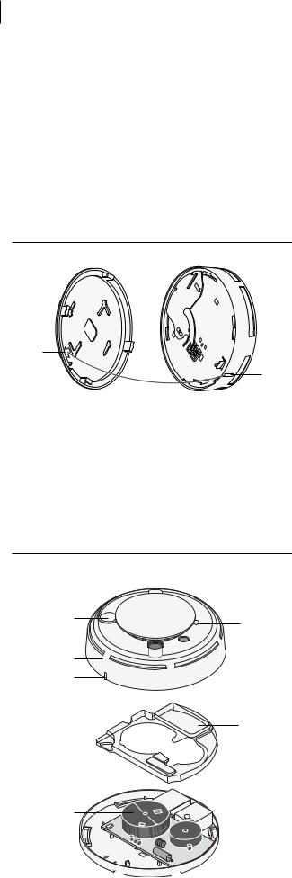
Figure 1. Mounting the alarm
Battery compartment |
|
|
(350 models only) |
Mounting base |
Gasket |
Base tamper tab |
Socket |
Connector |
Adhesive strip |
Electrical box |
|
|
assembly |
|
|
Figure 2. Wiring for tandem connections (maximum of 12)
|
Models: |
|
|
|
Models: |
|
|
|
|
|
Models: |
|
|
|
|
320A / 350 |
|
|
320ACC / 350CC |
|
|
|
320ACX / 350CX |
|
|||||
black |
white |
red |
black |
white |
red |
blue orange yellow |
violet |
violet |
black |
white |
red |
blue orange yellow |
violet |
violet |
|
|
|
|
|
|
|
|
Form A relay |
|
|
|
|
|
Form A relay |
|
|
Tandem bus |
|
|
|
|
|
Form C relay |
|
|
|
|
|
Form C relay |
|
|
red |
|
|
|
|
|
|
|
|
|
|
|
|
Unswitched |
|
black (hot) |
|
|
|
|
|
|
|
|
|
|
|
To additional |
120 VAC 60 Hz |
|
white (neutral) |
|
|
|
|
|
|
|
|
|
|
|
smoke alarms |
|
|
|
|
|
|
|
|
|
|
|
|
|
||
power supply |
|
|
|
|
|
|
|
|
|
|
|
|
|
|
|
|
|
|
|
|
|
|
|
|
|
|
|
|
|
2ESL 320A/350 Series Smoke Alarms Installation Instructions
6.Insert the connector assembly through the center hole in the mounting base and gasket (Figure 1) and attach the base to the mounting surface.
7.Plug the connector assembly into the socket on the back of the smoke alarm (Figure 1). For 350 Series units, you must install the battery and close the battery cover before the connector can be attached.
8.To attach the alarm to its mounting base, line up the arrow on the mounting base with the tab on the alarm (Figure 3). Insert the alarm into the base an turn clockwise approximately 15 degrees. It should snap firmly into place.
Figure 3. Arrow and tab alignment
Arrow
Tab
9.Apply AC power to the alarm.
10.To test the installation, press the test/silence button (Figure 4) for approximately 1 second and release. The unit should go into alarm, the LED should light steadily, and the sounder should emit a temporal pattern. Testing of one alarm will also cause alarms in tandem to sound. We recommend that you test each alarm individually.
11.Smoke-test the alarm. See Smoke test.
Figure 4. Alarm parts
Test silence button
LED
Smoke alarm cover
Tab
Clear plastic cover
Smokechamber
Wiring
Electrical wiring should be done by a licensed electrician. Use the following guidelines when wiring the unit:
•Observe all applicable building code requirements. Installation wiring shall conform with Article 76, Fire Protective Signaling Systems, of the National Electrical Code NFPA 70 1996 Edition. The tandem bus qualifies as a power-limited circuit.
•Use 14 AWG cable or equivalent.
•Supply AC primary power either from a dedicated branch circuit or the unswitched portion of a branch circuit also used for power and lighting.
•When replacing a 320 Series alarm with a 320A/350 Series alarm, use the existing connector.
•When replacing a 320ACX Series alarm, use the existing 320 Series connector and cap the white/red and white/blue wires. Do not cap them together.
Single-station installation: Cap the red wire. Do not connect it to any other circuit.
Tandem-station installation:
•Do not connect more than 12 alarms in a tandem circuit per NFPA 72.
•Do not exceed 5,000 ft. (1524 m) for a tandem circuit.
•Use only 320 Series and 320A/350 Series alarms in tandem connections.
Alarm test
The alarm power, sounder, and electronic module should be tested monthly as follows:
Press the test/silence button (Figure 4) for approximately 1 second and release. The unit should go into alarm, the LED should light steadily, and the sounder should emit a temporal pattern.
If the alarm successfully goes into alarm, the unit has power and the electronic module is functioning properly.
If the alarm fails the test, first check that power is present. If power is present and it still fails, clean the alarm and replace the smoke chamber. See Smoke chamber replacement.
Smoke test
Test smoke alarms in place annually using one of the following methods:
•Use Smoke! in a can® (SM-200), a canned aerosol simulated smoke and follow the directions on the can; or
•Test the alarm with smoke. Hold a smoldering punk or cotton wick close to the smoke entry openings. Gently direct smoke into the alarm for 20 seconds or until an alarm is indicated.
Be sure to properly extinguish the smoke source after testing! The alarm LED should light steadily and the sounder should activate until the smoke clears or the text/silence button (Figure 4) is pressed.
Slot 
 Slot
Slot
 Loading...