

Page 1
North America
T 888 437 3287
F 561 998 6224
Asia
T 65 639 19314
F 65 639 19306
Australia
T 61 3 9239 1200
F 61 3 9239 1299
Canada
T 800 267 6317
F 613 737 5517
EMEA
T 48 58 326 22 40
F 48 58 326 22 41
Latin America
T 503 885 5700
F 561 994 6572
Email: rs-bctsupport@fs.utc.com
Web site: www.utcfireandsecurity.com
© 2011 UTC Fire & Security. All rights reserved.
UTC Fire & Security, 9 Farm Springs Road,
Farmington, CT 06034-4065, USA
Model 1000/1010 Dual Tech
Proximity/Magnetic Stripe Reader
Installation Manual
460350002H, June 2011
Page 2

Copyright © 2011 UTC Fire & Security. All Rights Reserved.
This document may not be copied in whole or in part or otherwise reproduced without prior written consent from UTC Fire & Security, except where
specifically permitted under US and international copyright law.
Disclaimer The information in this document is subject to change without notice. UTC
Trademarks
and patents
Intended use Use this product only for the purpose it was designed for; refer to the data
compliance
Regulatory
Fire & Security assumes no responsibility for inaccuracies or omissions and
specifically disclaims any liabilities, losses, or risks, personal or otherwise,
incurred as a consequence, directly or indirectly, of the use or application of
any of the contents of this document. For the latest documentation, contact
your local supplier or visit us online at www.utcfireandsecurity.com.
This publication may contain examples of screen captures and reports used
in daily operations. Examples may include fictitious names of individuals
and companies. Any similarity to names and addresses of actual businesses or persons is entirely coincidental.
The Model 1000/1010 Dual Tech Proximity/Magnetic Stripe Reader name
and logo are trademarks of UTC Fire & Security.
Other trade names used in this document may be trademarks or registered
trademarks of the manufacturers or vendors of the respective products.
sheet and user documentation for details. For the latest product information,
contact your local supplier or visit us online at www.utcfireandsecurity.com.
FCC
This equipment has been tested and found to comply with the limits for a
Class A digital device, pursuant to part 15 of the FCC Rules. These limits
are designed to provide reasonable protection against harmful interference
when the equipment is operated in a commercial environment. This equipment generates, uses, and can radiate radio frequency energy and, if not
installed and used in accordance with the instruction manual, may cause
harmful interference to radio communications.
You are cautioned that any changes or modifications not expressly
approved by the party responsible for compliance could void the user's
authority to operate the equipment.
2002/96/EC (WEEE directive): Products marked with this symbol cannot be
disposed of as unsorted municipal waste in the European Union. For proper
recycling, return this product to your local supplier upon the purchase of
equivalent new equipment, or dispose of it at designated collection points.
For more information see: www.recyclethis.info.
Manufacturer UTC Fire & Security
HQ and regulatory responsibility: UTC Fire & Security, 9 Farm Springs Road,
Farmington, CT 06034-4065, USA
Contact
information
For contact information see our Web site: www.utcfireandsecurity.com
Page 3

Contents
Introduction . . . . . . . . . . . . . . . . . . . . . . . . . . . . . . . . . . . . . . . . . .1
Safety . . . . . . . . . . . . . . . . . . . . . . . . . . . . . . . . . . . . . . . . . . . . . . .2
Radio interference. . . . . . . . . . . . . . . . . . . . . . . . . . . . . . . . . . .2
Electrostatic discharge (ESD) precaution . . . . . . . . . . . . . . . . .2
Product features. . . . . . . . . . . . . . . . . . . . . . . . . . . . . . . . . . . . . . .3
System requirements. . . . . . . . . . . . . . . . . . . . . . . . . . . . . . . . . . .4
Technical specifications . . . . . . . . . . . . . . . . . . . . . . . . . . . . . . . .5
Parts list . . . . . . . . . . . . . . . . . . . . . . . . . . . . . . . . . . . . . . . . . . . . .7
Installation overview . . . . . . . . . . . . . . . . . . . . . . . . . . . . . . . . . . .7
Mounting the reader. . . . . . . . . . . . . . . . . . . . . . . . . . . . . . . . . . . .8
Prepare the reader backplate . . . . . . . . . . . . . . . . . . . . . . . . . .8
Mounting diagrams . . . . . . . . . . . . . . . . . . . . . . . . . . . . . . . . .10
Configuring the reader . . . . . . . . . . . . . . . . . . . . . . . . . . . . . . . .17
Option select switch S2. . . . . . . . . . . . . . . . . . . . . . . . . . . . . .18
Door strike relay output jumper J6 . . . . . . . . . . . . . . . . . . . . .21
Factory default switch and jumper settings. . . . . . . . . . . . . . . 21
Connecting the reader. . . . . . . . . . . . . . . . . . . . . . . . . . . . . . . . .22
Pinouts . . . . . . . . . . . . . . . . . . . . . . . . . . . . . . . . . . . . . . . . . .22
Wiring diagrams . . . . . . . . . . . . . . . . . . . . . . . . . . . . . . . . . . .23
Testing the reader . . . . . . . . . . . . . . . . . . . . . . . . . . . . . . . . . . . .30
Indicators . . . . . . . . . . . . . . . . . . . . . . . . . . . . . . . . . . . . . . . .31
Regulatory approvals . . . . . . . . . . . . . . . . . . . . . . . . . . . . . . . . .33
UL . . . . . . . . . . . . . . . . . . . . . . . . . . . . . . . . . . . . . . . . . . . . . .33
CE . . . . . . . . . . . . . . . . . . . . . . . . . . . . . . . . . . . . . . . . . . . . . .34
i
Page 4

Model 1000/1010 Dual Tech Reader
ii
Installation Manual
Figures
Figure 1. Reader backplate preparation................................. 9
Figure 2. Model 1000/1010 reader dual-gang box mounting11
Figure 3. Model 1000/1010 reader, dual-gang box mounting,
Continued12
Figure 4. Model 1000/1010 reader, direct wall mounting .....13
Figure 5. Model 1000/1010 reader, surface mount box .......14
Figure 6. Model 1000/1010 reader, surface mount box, Con-
tinued15
Figure 7. Model 1000/1010 reader, 5029 back box or
environmental hood mounting16
Figure 8. Model 1000/1010 reader, jumper setting ..............17
Figure 9. Wiring diagram for F/2F installations: unsupervised
and 2-state supervision24
Figure 10. Wiring diagram for F/2F installations:
4-state supervision 26
Figure 11. Wiring diagram for Wiegand installations..............28
Page 5

Introduction 1
Introduction
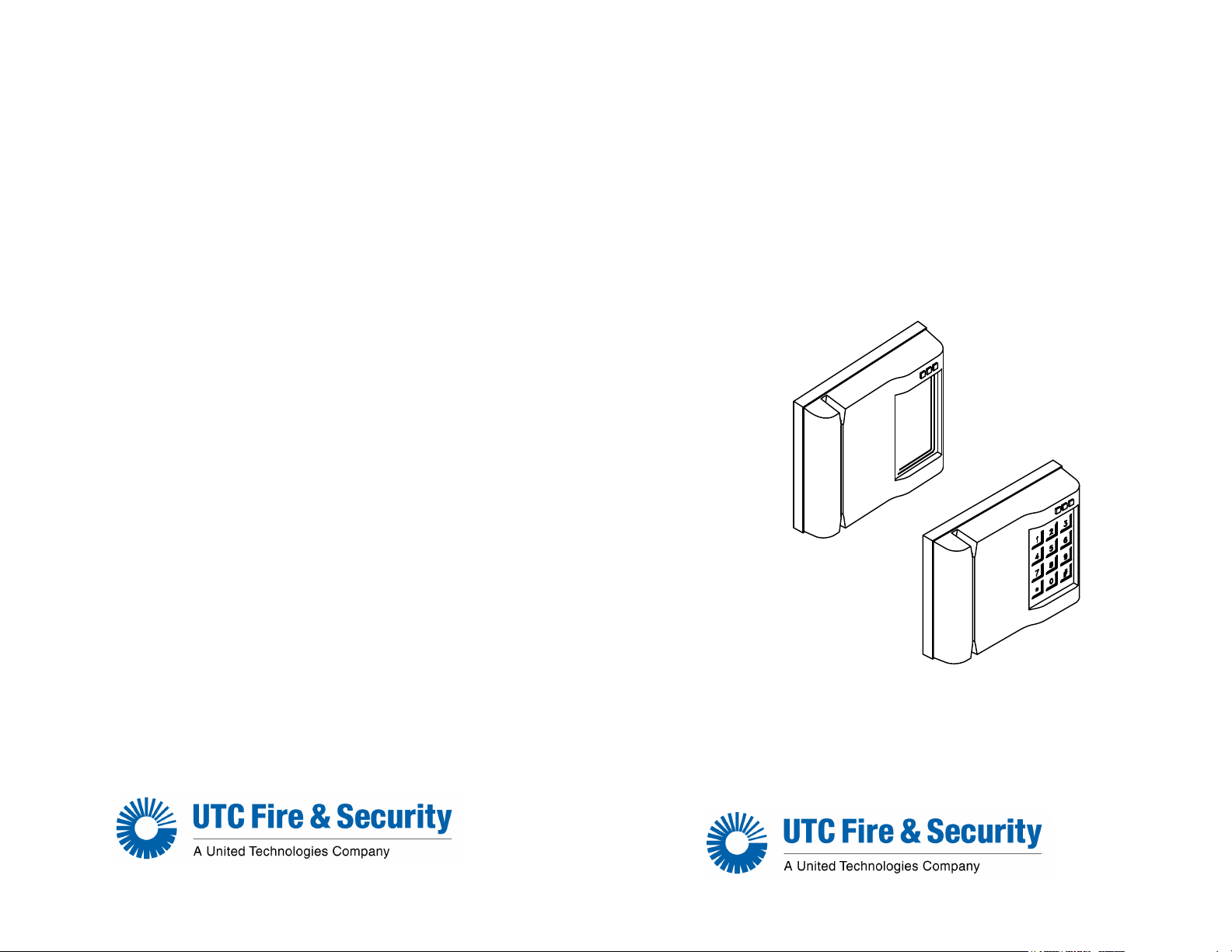
The Model 1000/1010 Dual Tech Proximity/Magnetic Stripe
reader combines proximity reader technology and
magstripe reader technology. The Model 1000 and 1010
readers are identical in their functionality, except that the
Model 1010 includes an integrated keypad used for the
entry of a personal identification number (PIN).
There have been five editions of the Model 1000/1010 Dual
Tech Proximity/Magnetic Stripe reader. The version of the
reader can be identified by the number of stripes on the
face-plate of the reader.
• First edition 2 stripes
• Second edition 3 stripes
• Third edition 1 stripe
• Fourth edition 0 stripes, labeled Model 1000
• Fifth edition 2 stripes with logo
This document provides instructions for the fifth edition of
the Model 1000/1010 Dual Tech Proximity/Magnetic Stripe
reader.
Page 6

Model 1000/1010 Dual Tech Reader
2
Installation Manual
Safety
Radio interference
WARNING: This is an FCC Class A product. In a domestic
environment, this product may cause radio
interference, in which case, the user may be
required to take adequate measures.
Electrostatic discharge (ESD) precaution
WARNING: Circuit board components are vulnerable to
damage by electrostatic discharge. ESD can
cause immediate or subtle damage to sensitive
electronic parts. An electrostatic charge can
build up on the human body and then discharge
when you touch a board. A discharge can be
produced when walking across a carpet and
touching a board, for example. Before handling
any board, make sure you dissipate your body’s
charge by touching ground. This discharges any
static electricity build-up.
Page 7

Product features 3
Product features
The Model 1000/1010 Dual Tech Proximity/Magnetic Stripe
readers offer:
• The ability to read ProxLite, ISO ProxLite, and Entreé
proximity badges and ProxLite keytags and ABA track 2
formatted magnetic stripe cards of up to 20 numeric
digits.
• Power-on self test.
• “Hot swap” support allowing a reader to be connected
or disconnected without powering down the micro.
• Built-in tamper switch for detecting cover or off-the-wall
tamper conditions.
• Switch-selectable supervised or unsupervised micro
communication.
• Switch-selectable door status and exit request (REX)
switch supervision.
• Switch-selectable 40-bit Wiegand 4001 or 4002 format
output.
• Switch-selectable 12-digit or IBM
output.
• A door strike relay for AC or DC operation, jumperselectable normally open or normally closed contacts.
• A keypad (Model 1010) for personal identification
number (PIN) entry.
• Weather resistant for outdoor use. See Mounting the
reader on page 8.
• Rugged polycarbonate housing.
• 12 to 48 VDC operation.
• LED and beeper user interface.
• Compatible replacement for the IBM Model 5029
reader.
®
10-digit badge ID
Page 8

Model 1000/1010 Dual Tech Reader
4
Installation Manual
System requirements
For UL compliant installation notes, refer to “UL listed
installations” on page 33
.
Host software
Microcontrollers • Micro/2 (Picture Perfect only)
Micro firmware For Micro/5-PX, Micro/5-PXN, Micro/PX-2000
Badge and keytag
formats
• Secure Perfect
• Picture Perfect
• Micro/4 (Picture Perfect only)
• Micro/5-PX with 2RP or 8RP
• Micro/5-PXN with 2RP or 8RP
• M5PXNplus with 2RP or 8RP
• Micro/PX-2000
• Micro/PXN-2000
• M2000PXNplus
• M3000PXNplus with 2RP or 8RP
and Micro/PXN-2000:
• Secure Perfect: 3.1.0.6 or later
• Picture Perfect: 1.7.0 or later
• Magstripe: ABA Track 2 (up to 20 digits)
• Proximity
Note: Proximity Perfect credentials, which
were discontinued in 2001, are not
supported.
®
Edition 3.0 or later
™
1.7 or later
Page 9

Technical specifications 5
Technical specifications
For UL compliant installation notes, refer to “UL” on page 33.
Operating
temperature
range
Relative humidity 5% to 95% (non-condensing)
Physical
dimensions
(HxWxD)
Index of
protection
Input voltage
range
Reader power
consumption
Heater kit power
consumption
Cable
specifications
without heater kit: +33
o
C)
+66
with heater kit: -31
4.75” x 6.00” x 1.63”
(121 mm x 152 mm x 42 mm)
IP34
12 to 48 volts +/- 5% measured at the reader
65 mA @ 12 VDC nominal (90 mA with relay/LED
active)
40 mA @ 48 VDC nominal (50 mA with relay/LED
active)
Max: 105mA @ 15 VDC nominal (with relay/LED
active)
400 mA @ 24 VAC
Belden 8725 or equivalent, 20 AWG minimum,
shielded pairs
o
F to +150o F (+1o C to
o
F to +150o F (-35o C to +66o C)
Maximum
cabling distance
Door strike relay 1.0 A @ 30 VDC maximum
3000 ft (914 m) @ 12 VDC with 20 AWG cable
5000 ft (1524 m) @ 12 VDC with 20 AWG cable
and local power
3000 ft (914 m) @ 48 VDC with 20 AWG cable
5280 ft (1609 m) @ 48 VDC with 18 AWG cable
Page 10

Model 1000/1010 Dual Tech Reader
6
Installation Manual
Read range ProxLite: up to 6 inches (152 mm).
ISO ProxLite: up to 5 inches (127 mm)
ProxLite Keytag: up to 2 inches (76 mm)
Entrée: up to 5 inches (127 mm)
Magnetic stripe ABA Track 2 formatted cards up to 20 digits
Agency
approvals
CE
UL 294
FCC Class A part 15
Page 11

Parts list 7
Parts list
• Model 1000 reader
• Model 1010 reader
• Optional 1000/1010 to 5029 mounting plate
• Optional housing, surface mount
• Optional tool, 1/8 inch hex tamper key
• Optional 1000/1010 cold weather kit
Refer to the UTC Fire & Security product catalog for part
numbers and ordering information.
Installation overview
The following steps are general instructions for installing
the Model 1000/1010 Dual Tech Proximity/Magnetic Stripe
reader. Each step is explained in further detail in the
sections that follow.
1. Mount the reader backplate.
Refer to “Mounting the reader” on page 8.
2. Configure the reader.
Refer to “Configuring the reader” on page 17.
3. Connect the reader.
Refer to “Connecting the reader” on page 22.
4. Test the reader.
Refer to “Testing the reader” on page 30.
Page 12

Model 1000/1010 Dual Tech Reader
8
Installation Manual
Mounting the reader
The reader comes with a backplate suitable for mounting
directly onto a standard dual-gang U.S. electrical box. For
other mounting applications, see Figure 2 through Figure 7.
If mounting outdoors, a 1/8" (3.175 mm) foam gasket
(installer supplied) is highly recommended. Ensure that
adequate cutouts are provided for the connectors and
tamper spring. For installations where below freezing
temperatures are anticipated, order and install the optional
Cold Weather Kit. Please refer to your product catalog for
the Cold Weather Kit part number.
If readers are to be mounted side-by-side, their centers
should be offset by at least 10 inches to provide
interference-free operation.
Prepare the reader backplate
The plastic backplate on the Model 1000/1010 Dual Tech
Proximity/Magnetic Stripe reader, can be adapted for field
wiring termination to an 11-pin Phoenix connector or a 9-pin
D-subminiature connector (DB9).
Unscrew the backplate from the reader assembly and place
it on a flat surface. Use a utility knife to remove the
appropriate connector cutout. See item 1 in Figure 1.
Additionally, the reader can be configured for off-the-wall
tamper operation by punching out the appropriate hole on
the reader backplate exposing the tamper spring. See item
2 in Figure 1.
Page 13

Figure 1. Reader backplate preparation
Mounting the reader 9
1 Prior to mounting the backplate, remove the connector cutout to
suit the installation.
2 Punch or cut to enable off-the-wall tamper.
3 For mounting installations other than a standard dual-gang box
or 5029 plate, select other mounting hole locations on the
backplate. Place the backplate face down on a flat surface and
then using a small Phillips head screw driver or round punch,
punch through selected mounting holes.
Page 14

Model 1000/1010 Dual Tech Reader
10
Installation Manual
Mounting diagrams
There are four reader mounting methods:
1. Dual-gang box mounting. Refer to Figure 2,
“Model 1000/1010 reader dual-gang box mounting,”
on page 11 and Figure 3, “Model 1000/1010 reader,
dual-gang box mounting, Continued,” on page 12.
2. Direct wall mounting. Refer to Figure 4, “Model
1000/1010 reader, direct wall mounting,” on
page 13
3. Surface box mounting. Refer to Figure 5, “Model
1000/1010 reader, surface mount box,” on page 14
and Figure 6, “Model 1000/1010 reader, surface
mount box, Continued,” on page 15.
4. 5029 back box and environmental hood
mounting. Refer to Figure 7, “Model 1000/1010
reader, 5029 back box or environmental hood
mounting,” on page 16.
Page 15

Figure 2. Model 1000/1010 reader dual-gang box mounting
Mounting the reader 11
Page 16

Model 1000/1010 Dual Tech Reader
12
Installation Manual
Figure 3. Model 1000/1010 reader, dual-gang box mounting, Continued
Page 17

Figure 4. Model 1000/1010 reader, direct wall mounting
Mounting the reader 13
Page 18

Model 1000/1010 Dual Tech Reader
14
Installation Manual
Figure 5. Model 1000/1010 reader, surface mount box
Page 19

Mounting the reader 15
Figure 6. Model 1000/1010 reader, surface mount box, Continued
Page 20

Model 1000/1010 Dual Tech Reader
16
Installation Manual
Figure 7. Model 1000/1010 reader, 5029 back box or
environmental hood mounting
Page 21

Configuring the reader 17
Configuring the reader
The configuration and operation of the reader are controlled
by setting the following switch and jumper:
• S2: Option select switch
• J6: Door strike relay output
Refer to Figure 8 for the location of the switch and the
jumper.
Figure 8. Model 1000/1010 reader, jumper setting
Page 22

Model 1000/1010 Dual Tech Reader
18
Installation Manual
Option select switch S2
The option select switch controls the operating mode,
badge mode, beeper output, indicator mode, and Wiegand
format. Refer to the tables below for switch settings
Note: Switch S2-8 is reserved for future use.
Operating mode
Switch S2-1 and S2-2 determine the operating mode:
Wiegand, F/2F or supervised F/2F operating mode.
Table 1. Operating mode
Mode S2-1 S2-2
Wiegand OFF OFF
F/2F ON OFF
Supervised F/2F ON ON
Wiegand mode: The reader sends Wiegand data (2 data
signals) to the micro. No supervision is performed. REX
and door input states are not reported.
F/2F mode: The reader sends and receives F/2F data (1
data signal) to and from the micro. Communication failures
between the reader and the micro are not reported. REX
and door input states are not reported.
Supervised F/2F mode: The reader sends and receives F/
2F data (1 data signal) to and from the micro.
Communication failures between the reader and the micro
are reported. REX and door input states are reported.
Page 23

Configuring the reader 19
4-state door/REX supervision
Switch S2-3 sets the supervision at 4-state or 2-state.
Table 2. 4-state door/REX supervision
Supervision S2-3
4-State Door/REX Supervision ON
2-State Door/REX Supervision OFF
4-state: REX and door inputs are reported as cut line, short
circuit, closed circuit, and open circuit. Ensure that end-ofline resistors are installed properly. Refer to the wiring
diagram shown in Figure 10 on page 26.
Note: To enable four-state supervision for the door and the REX,
install a jumper at position J8. Both points must be terminated
with resistors as shown in
The REX terminals on the reader shall not be connected in UL
listed installations.
Figure 10 on page 26.
2-state: REX and door inputs are reported as open circuit
and closed circuit.
Note: Door/REX supervision has no effect in Wiegand or F/2F mode.
The state of these inputs are not reported.
Badge mode
Switch S2-4 determines the badge mode: 10 digit or 12
digit.
Table 3. Badge mode
Badge mode S2-4
IBM 10 digit output ON
Standard 12 digit output OFF
Page 24

Model 1000/1010 Dual Tech Reader
20
Installation Manual
Beeper output
Switch S2-5 determines if the beeper will sound.
Table 4. Beeper output
Beeper output S2-5
Enabled ON
Disabled OFF
Indicator mode
Switch S2-6 sets the indicator mode to IBM or standard
mode LED and sound indicators. Refer to “Indicators” on
page 31 for more information.
Table 5. Indicator mode
Indicator mode S2-6
IBM indicators ON
Standard indicators OFF
Wiegand format
Switch S2-7 sets the Wiegand output format to 4001 or
4002.
Table 6. Wiegand format
Wiegand format S2-7
4001 ON
4002 OFF
Page 25

Configuring the reader 21
Door strike relay output jumper J6
Jumper J6 controls the normally closed or normally open
state of the door strike relay
Table 7. Door strike relay output
Jumper Jumper selection Contact
J6 Pins 1 and 2 Shorted Normally Closed Selected
Pins 2 and 3 Shorted Normally Open Selected
Factory default switch and jumper settings
Table 8. Factory default settings
Switch/
Jumper
S2-1 ON Supervised F/2F
S2-2 ON Supervised F/2F
S2-3 OFF 2-state door/REX supervision
S2-4 ON IBM 10-digit badge output
S2-5 ON Beeper output enabled
S2-6 ON IBM indicators
S2-7 OFF 4002 Wiegand format
J6 Pins 2 and 3 shorted Strike relay contact normally open
Switch/Jumper
selection Setting
Page 26

Model 1000/1010 Dual Tech Reader
22
Installation Manual
Connecting the reader
Pinouts
The Model 1000/1010 Dual Tech Proximity/Magnetic Stripe
reader contains two connectors: a standard 9-pin Dsubminiature connector (DB9) and an 11-pin Phoenix
connector. The pinouts for the DB9 connector are listed in
the table below. The pinouts for the Phoenix connector are
listed on page 23.
Note: Signals on the DB9 connector are also available on the Phoenix
connector to allow the installer to choose either the DB9 or the
11-pin Phoenix for connecting the reader.
Table 9. Pinouts for the DB9 connector
PIN
number Signal
1Ground Black
2 Switch common Orange
3F/2F Data 1 Red
4 Door strike relay output Blue
5 Exit DI (exit request button) Violet
6 Door strike relay return White
7 12 to 48 VDC Yellow
8 Door DI (door contact switch) Grey
9 Door DO input from microcontroller
(to control the strike relay)
Cable color
(BELDEN)
Brown
Page 27

Connecting the reader 23
Table 10. Pinouts for the Phoenix connector
Cable color
PIN # Signal
1
2
3 Door DO input from microcontrollers
4 Door DI (door contact switch) Blue
5 12 to 48 VDC Violet
6 Door strike relay return White
7 Wiegand data 0 Yellow
8 Door strike relay output Gray
9 F/2F or Wiegand data 1 Brown
10 Exit DI (exit request button)
11 Ground/switch common
a. Used for 4-state supervised DI points only. See Figure 10.
Exit request return
Door return
(to control the strike relay)
a
a
(BELDEN)
Black
Orange
Red
Wiring diagrams
Use the wiring diagrams starting on page 24 to connect the
reader to the micro.
• Refer to Figure 9, “Wiring diagram for F/2F installations:
unsupervised and 2-state supervision,” on page 24.
• Refer to Figure 10, “Wiring diagram for F/2F
installations: 4-state supervision,” on page 26.
• Refer to Figure 11, “Wiring diagram for Wiegand
installations,” on page 28.
Page 28

Model 1000/1010 Dual Tech Reader
24
Installation Manual
Figure 9. Wiring diagram for F/2F installations: unsupervised and 2-state
supervision
Page 29

Connecting the reader 25
Note: Unless otherwise specified:
1 Protection diodes may be 1N4002, 1N4003, or 1N4004 for the door strike assembly (supplied by
the installer) for DC strikes only.
2 Fuse, power supply (fused primary), and relay provided by the installer/customer.
3 For 12 VDC micros, the maximum cabling distance is 3,000 feet (914 m), using shielded 20 AWG
cable.
For 48 VDC micros, the maximum cabling distance is 5,280 feet (1609 m), using shielded 18 AWG
cable, and 3,000 feet (914 m), using shielded 20 AWG cable.
4 Connect all shields together at the micro end, connect to ground stud in the cabinet using 14 AWG
wire. No shield connections at reader.
5 Micro/2 and Micro/4 only: If wiring door DI switch through reader (as shown), door DI on reader
board must be connected to Ground.
6 For 12 VDC micros, a 12 VDC user-supplied power supply, located at the reader, may be installed
to extend the maximum cable distance to 5,000 feet (1524 m) when using shielded 20 AWG cable.
For 48 VDC micros, a local power supply should not be used.
7 Local power supply must be at the same voltage level as the micro power supply.
8 The Micro/5 2RP and the Micro/5 8RP can only be used with a Micro/5 operating at 12 VDC.
9 Door contacts and REX switch connections are for 2-state Door/REX supervision when configured
for supervised F/2F only. No connections should be made when the reader is configured for
unsupervised F/2F mode. Request to exit (REX) terminals on the reader are not to be connected for
UL listed installations.
10 Blocking diode may be type 1N5817 or part number 521224001 (included with reader). The diode
must be installed in a secure location, not accessible through the reader removal.
Page 30

Model 1000/1010 Dual Tech Reader
26
Installation Manual
Figure 10.Wiring diagram for F/2F installations:
4-state supervision
Page 31

Connecting the reader 27
Note: Unless otherwise specified:
1 Protection diodes may be 1N4002, 1N4003, or 1N4004 for the door strike assembly (supplied by
the installer) for DC strikes only.
2 Fuse, power supply (fused primary), and relay provided by the installer/customer.
3 For 12 VDC micros, the maximum cabling distance is 3,000 feet (914 m), using shielded 20 AWG
cable.
For 48 VDC micros, the maximum cabling distance is 5,280 feet (1609 m), using shielded 18 AWG
cable, and 3,000 feet (914 m), using shielded 20 AWG cable.
4 Connect all shields together at the micro end, connect to ground stud in the cabinet using 14 AWG
wire. No shield connections at reader.
5 Micro/2 and Micro/4 only: If wiring door DI switch through reader (as shown), door DI on reader
board must be connected to Ground.
6 For 12 VDC micros, a 12 VDC user-supplied power supply, located at the reader, may be installed
to extend the maximum cable distance to 5,000 feet (1524 m) when using shielded 20 AWG cable.
For 48 VDC micros, a local power supply should not be used.
7 Local power supply must be at the same voltage level as the micro power supply.
8 The Micro/5 2RP and the Micro/5 8RP can only be used with a Micro/5 operating at 12 VDC.
9 Resistors for 4-state Door/REX supervision are 1 K ohm, ¼ watt +/- 5% minimum. Tolerance of
+/- 2% is recommended mode. Request to exit terminals on the reader are not to be connected in
UL listed installations.
10 Blocking diode may be type 1N5817 or part number 521224001 (included with reader). The diode
must be installed in a secure location, not accessible through the reader removal.
Page 32

Model 1000/1010 Dual Tech Reader
28
Installation Manual
Figure 11.Wiring diagram for Wiegand installations
Page 33

Connecting the reader 29
Note: Unless otherwise specified:
1 Protection diodes may be 1N4002, 1N4003, or 1N4004 for the door strike assembly (supplied
by the installer) for DC strikes only.
2 Fuse, power supply (fused primary), and relay provided by the installer/customer.
3 For 12 VDC or 48 VDC micros, the maximum cabling distance is 2,000 feet (914 m), using
shielded 20 AWG cable. A local power supply should not be used.
4 Connect all shields together at the micro end, connect to ground stud in the cabinet using
14 AWG wire. No shield connections at reader.
5 Micro/2 and Micro/4 only: If wiring door DI switch through reader (as shown), door DI on reader
board must be connected to Ground.
6 The Micro/5 2RP can only be used with a Micro/5 operating at 12 VDC.
7 Blocking diode may be type 1N5817 or part number 521224001 (included with reader). The
diode must be installed in a secure location, not accessible through the reader removal.
Page 34

Model 1000/1010 Dual Tech Reader
30
Installation Manual
Testing the reader
Perform the following test procedure to verify correct
operation of the Model 1000/1010 Dual Tech Proximity/
Magnetic Stripe readers:
1. Check all cabling and electrical connections from
the reader to the microcontroller.
2. Verify that the microcontroller is properly configured
(refer to the appropriate microcontroller manual).
3. Ensure the proper version of the firmware is
installed in the microcontroller. Refer to the
appropriate microcontroller manual.
4. Verify that the reader is properly configured. Refer
to “Configuring the reader” on page 17.
5. Close the tamper switch by joining the reader and
backplate so that the tamper alarm is suppressed or
by ensuring the spring is compressed when using
off-the-wall tamper.
6. Apply power to the reader and verify that the poweron self test completes as described in the table
“Indicators” on page 31.
7. Verify that the reader is not beeping. If the reader is
beeping, refer to the troubleshooting guide at the
end of this manual.
8. Verify proper reader operation as follows:
a. Select a known good test badge. Be sure that
the badge is properly enrolled in the host
system. If the reader is used with a keypad,
assign a proper PIN.
Page 35

Testing the reader 31
b. Ensure that the door is closed and latched. This
is the first step to verify that the reader strike
relay is wired properly.
c. Pass the card through or present a card to the
reader. Observe that the reader behaves as
described in the table “Indicators” on page 31.
d. If used with a keypad, enter the PIN number and
press #. Observe that the reader behaves as
described in the table “Indicators” on page 31.
e. Observe that the green LED turns on, indicating
a valid access has been granted by the host.
f. Open the door. This verifies that the reader
strike relay operates properly.
Indicators
A tri-color LED (red, yellow, and green), and a beeper are
incorporated into the reader and operate as indicated in the
following table.
Table 11. Indicators
Standard indicators
Condition
Power-on
self test
Reader ready Yellow LED on
Card read Yellow LED blinks off
(S2-6 = OFF)
All LEDs turn on,
all LEDs turn off,
1 short beep
continuously
briefly,
1 short beep
IBM indicators
(S2-6 = ON)
All LEDs turn on,
all LEDs turn off,
1 short beep
Red LED on
continuously
Red LED on
continuously,
Yellow LED blinks on
briefly,
1 short beep
Page 36

Model 1000/1010 Dual Tech Reader
32
Installation Manual
Table 11. Indicators
Standard indicators
Condition
PIN entry
(Model 1010 in
supervised mode
only)
(S2-6 = OFF)
Green LED flashes
quickly, 1 short beep
every time a key is
pressed
Valid access Yellow LED on
continuously,
Green LED on until door
strike is deactivated
Loss of
communication
(supervised
Red LED flashes slowly,
3 short beeps every
30 seconds
mode only)
Ta mp e r
(supervised)
Red LED flashes quickly,
3 short beeps every 30
seconds
Ta mp e r
(unsupervised)
Red LED on continuously,
3 short beeps every
30 seconds
Reader wired for
4-state
supervision, but
S2-3 configured
for 2-state
Red LED flashes quickly
5 times every 10
seconds,
5 short beeps every
10 seconds
IBM indicators
(S2-6 = ON)
Red LED on
continuously,
Yellow LED blinks on
every time a key is
pressed or stays on
until PIN complete,
1 short beep every
time a key is pressed
Red LED on
continuously,
Green LED on until
door strike is
deactivated
Red LED flashes
quickly 3 times every
30 seconds,
3 short beeps every
30 seconds
Red LED flashes
quickly 5 times every
30 seconds,
5 short beeps every
30 seconds
Red LED flashes
quickly 5 times every
30 seconds,
5 short beeps every 30
seconds
Red LED flashes
quickly 5 times every
10 seconds,
5 short beeps every
10 seconds
Page 37

Regulatory approvals 33
UL listed installations
Regulatory approvals
UL
The following are the results of the UL evaluation of the
Model 1000/1010 Dual Tech Proximity/Magnetic Stripe
readers:
o
• Operating temperature range: +32
o
(+0
C to +49o C)
• Relative humidity: 85%
F to +120o F
• The Cold Weather Kit was not evaluated by UL.
• The Model 1000/1010 readers were evaluated by UL for
indoor use only.
• Using the internal relay of the reader to control/activate
the door strike will result in an installation that is not UL
compliant.
• The Model 1000/1010 readers were evaluated by UL for
use with the Micro/5-PXN, Micro/5-PX, Micro/PXN2000, and the Micro/PX-2000. Micro/2, Micro/4,
M5PXNplus, M2000PXNplus, and M3000PXNplus
installations were not included in the evaluation.
Page 38

Model 1000/1010 Dual Tech Reader
Signature of representative/manufacturer: RafaelMartinez
ComplianceLeader,Access
791ParkofCommerceBlvd,Suite100
BocaRaton,Fl33487
Place : Boca Raton, FL
Date : 14 June 2011
Page 1 of 2
MANUFACTURERS
DECLARATION OF CONFORMITY
For
Product identification:
Model/type : : 1000/1010
(w/110169001 pcba)
BOM revision level : 1000= G 1010=J
Category (descript ion) : Reader Dual Tec hnology
Brand :
Manufacturer:
UTC Fire & Security,
Americas Corp., Inc.
3211 Progress Dr.
Lincolnton, NC 28092
USA
EU Representative:
UTC Fire & Security B.V.
Kelvinstraat 7
6003 DH Weert
The Netherlands
Concerning RTTE
EMC Safety Radio
A sample of the
product
has been tested by:
PSE
12955 Bellamy Brothers
Blvd.
Dade City, FL 33525
PSE Inc
12955 Bellamy
Brothers Blvd
Dade City, Fl
PSE Inc
12955 Bellamy Brothers
Blvd
Dade City, Fl
Test report reference
07F257I 03F345 03F345C
Applied standards
EN50130-4(1995) +A1(1998)
+A2(2003)
EN60950-1
(2001)
EN300 330 v1.3.1
(2001/2006)
Equipment class identifier (RF products falling under the scope of R&TTE)
Not Applicable x None (class 1 product)
(class 2 product)
Means of conformity
We declare under our sole responsibility that this product is in conformity with Directive 1999/5/EC (R&TTE),
2004/108/EC (EMC), 2006/95/EC (LVD), and 93/68/EEC (Marking) based on test results using harmonized
standards in accordance with the Directives mentioned.
34
Installation Manual
CE
Page 39

Signature of representative/manufacturer: RafaelMartinez
ComplianceLeader,Access
791ParkofCommerceBlvd,Suite100
BocaRaton,Fl33487
Place : Boca Raton, FL
Date : 14 June 2011
Page 2 of 2
Model listing (list of all product variants or models for which this declaration is valid)
Model BOM revision level
430138001 Reader, Dual Technology, Prox/Magstripe G
430139001 Reader, Dual Technology, Keypad, Prox/Magstripe J
Regulatory approvals 35
Page 40

Model 1000/1010 Dual Tech Reader
Outside Micro/5 Enclosure
36
Installation Manual
CE/FCC compliance
To make the Model 1000/1010 Dual Tech Proximity/
Magnetic Stripe reader installation CE and FCC compliant,
the cable connecting the reader to the micro must have its
shield grounded at the micro, according to one of the
methods specified in the figures below.
Figure 12.Typical installation (Internal to the micro)
Figure 13.Typical installation (External to the micro)
 Loading...