

Page 1
GE
EST Fire & Life Safety
Security
Overview
EST3 Power supplies consist of two assemblies, a high efficiency
switch mode power supply card and a power supply monitor
module. The monitor module mounts to the local rail and distributes
the power from its supply to the local rail. The local rail distributes
power from all power supplies to other local rail modules and user
interface cards resulting in “Shared Power” throughout the system.
By paralleling the power supplies on a rail maximum utilization of
available power is possible, resulting in fewer power supplies. Up to
four power supplies combine in a single enclosure providing up to
28 amps of available power. Battery backup is provided using from
one to four sets of batteries, depending on standby power requirements.
Power supplies mount to the back of the chassis units or wallboxes.
The associated power supply monitor module mounts on the local
rail providing system power distribution and mounting space for
any control display module. Access to auxiliary power is via easily
accessible terminal blocks located on the power supply monitor module. Each power supply produces 7 Amps of filtered and
regulated power. With four power supplies located in an enclosure
(one primary and three booster power supplies) 28 amps of current
is available for local rail modules, control display modules and the
eight auxiliary 3.5 amp power outputs (two per supply).
EST3 Multiplexed Fire Alarm System
Standard Features
High efficiency switch mode
•
Increased power distribution efficiency
•
- power supplies parallel allowing up to 28 amps in a single node
120 or 230 Vac operation
•
7 AMP filtered and regulated
•
Two 3.5 AMP outputs
•
Temperature compensated, dual rated battery charger
•
Electronic power limiting
•
Automatic load testing of batteries
•
EST3 Power Supplies
3-PPS/M series, 3-BPS/M series,
3-BBC/M series
Power
Supply
Monitor
Module
and EN54-4:1997+A1:2002+A2
Data Sheet 85010-0059 Issue 10
Not to be used for installation purposes. Page 1 of 4
EN54-2:1997+A1
pending
Page 2
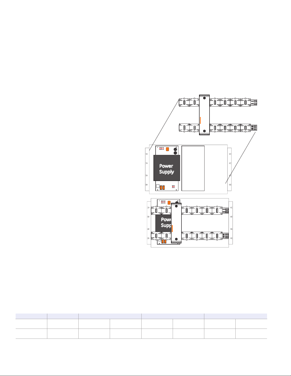
Application
J8
J9
J10
J11
J8
J9
J10
J11
Power
Supply
L
R
M
Power
Supply
J8
J9
J10
J11
J8
J9
J10
J11
L
R
M
Power
Distribution
Module
(EN-54 only)
Power
Supply
J8
J9
J10
J11
J8
J9
J10
J11
L
R
M
The primary power supply provides the system with battery charging and voltage regulation. Software configures the charger to
either 10-24 AH batteries or 30-65 AH batteries and controls the
high/low charge rates. Batteries mounted in the same enclosure as
the power supply, have their charge rate monitored and adjusted
based on the local enclosure temperature, keeping charging rates
within battery specification. For remote batteries a temperature
probe is monitored in the remote battery cabinet and charge rates
are adjusted automatically. Battery damage is unlikely to occur
when environmental short term conditions are outside of normal
operating ranges.
The EST3 power supplies automatically load test batteries by
shutting down the battery charger and placing a load across the
battery. If the battery voltage is outside the specification range the
power supply reports a trouble. The trouble clears if the battery is
able to recover and pass future load tests.
Battery leads are electronically short circuit protected. If a short
occurs in the battery leads the charger automatically disables
itself and causes a trouble. The system will constantly look to see if
the short has cleared. If the short clears the system automatically
restores.
During operation on standby batteries, battery voltage is constantly monitored. A trouble is reported if the battery voltage falls below
a specified value.
EST3 power supplies provide specific information back to the 3CPU(1) designed to help speed trouble shooting of system functions.
Should a power supply detect a fault, specific diagnostic codes
are available to speed trouble shooting. The 3-LCD will display the
power supplies address, a specific trouble code, and a text message
describing the specific trouble. Text messages are easy to understand and include items like: Battery Trouble, Aux Power Overload
Circuit 1, Aux Power Overload Circuit 2.
Engineering Specification
The fire alarm power supplies must be capable of being paralleled
and to load share. Multiple power supplies must be capable of being
backed up with a single 24 volt battery set. Each power supply shall
be capable of charging up to 65 AH batteries. The power supply
must be able to perform an automatic load test of batteries and
return a trouble if the batteries fall outside a predetermined range.
Power supplies must incorporate the ability to adjust the charge
rate of batteries based on ambient temperatures. It shall be possible to adjust for ambient temperature changes in local cabinets as
well as remote cabinets.
Installation and Mounting
Power Supply Rules
1. Each battery set needs one charger, either a 3-PPS/M or a 3-BBC/M.
2. Each power supply must be connected to a battery set using an identical length and gauge of wire to keep voltage drops identical.
3. Distribute power supplies and loads evenly across rails.
4. All battery sets for a panel must be the same capacity (AH), same manufacturer, and same manufacturing date code.
The Table below illustrates the combinations of power supplies and batteries that meet all the power supply rules.
24 VDC Power Supply Output Current
7A 14A 21A 28A
Battery
Requirements
Required
Modules
One Set,
65 AH max
1 3-PPS/M
One Set,
65 AH max
1 3-PPS/M
1 3-BPS/M
Two Identical
Sets, 65 AH max
1 3-PPS/M
1 3-BBC/M
1 3-PPS/M 2 3-
One Set,
65 AH max
BPS/M
Three Identical
Sets, 65 AH max
1 3-PPS/M
2 3-BBC/M
Not to be used for installation purposes. Page 2 of 4
One Set,
65 AH max
1 3-PPS/M
3 3-BPS/M
Data Sheet 85010-0059 Issue 10
Four Identical
Sets, 65 AH max
1 3-PPS/M
3 3-BBC/M
Page 3

Primary
Power
Supply
Booster
Power
Supply
24Vdc *
2 x 3.5A
24Vdc *
2 x 3.5A
124 3
Utility
Power
Power
To Rail
Auxillary
Power
Takeoff
2 x 3.5A
Primary
Power Supply
Monitor Module
Power
Supply
Monitoring
Rails
[1] From battery temperature probe terminals.
[2] From battery and from temperature probe terminals if 3-BTSEN-E used.
* Nominal Voltage
124 3
Auxillary
Power
Takeoff
2 x 3.5A
Booster
Power
Supply
Booster
Power
Supply
24Vdc *
2 x 3.5A
24Vdc *
2 x 3.5A
124 3
Auxillary
Power
Takeoff
2 x 3.5A
Booster
Power Supply
Monitor Module
Rails
124 3
Auxillary
Power
Takeoff
2 x 3.5A
[1]
[2] [2] [2]
Typical Wiring
Specifications
Catalog Number 3-PPS/M & 3-BBC/M 3-BPS/M
3-PPS/M-230 & 3-
BBC/M-230
3-BPS/M-230
Agency Approvals UL, ULC U L, ULC UL, ULC UL, ULC LPCB EN54*, CE EN54*
Input Voltage 120 Vac (+10%, -15%), 50-60 Hz 230 Vac (+10%, -15%), 50-60 Hz
Brownout Level < or = 102 Vac 96 Vac < or = 195 Vac 184 Vac < or = 195 Vac 188 Vac
3-PPS/M-230
included with 3-CPU3
current
3-BBC/M-230
Alarm: 70 mA
Standby: 70 mA
Alarm: 50 mA
Standby: 50 mA
Current
Requirements
3-PPS/M included
with 3-CPU3 current
3-BBC/M
Alarm: 70 mA
Standby: 70 mA
Alarm 50mA
Standby 50mA
Input Current 3.0 A 1.5 A
Total Output Current Special Applications: 7.0 Amps
Battery Charging
Capacity
65 AH Sealed
Lead-Acid
None
65 AH Sealed
Lead-Acid
None
Low Battery Trouble 24 Vdc 22.5 Vdc
Deep Discharge
Cutoff
Mounting
Requirements
Output Voltage 24 Vdc Nominal
Auxiliary Output
Current
Auxiliary Output
Terminal Capacity
Output Protection Electronic power limiting & heat sink temperature
Ground Fault
Detection
*EN54-2:1997+A1 and EN54-4:1997+A1:2002+A2 pending
19.5 Vdc 20.0 Vdc
1 LRM space,
1 chassis footprint
Two sources of 3.5 Amps each taken from total output current
18 AWG to 12 AWG (1 mm² to 2.5 mm²)
< 10K Ohms
3-PPS/M-230-E &
3-BBC/M-230-E
3-BPS/M-230-E
3-PPS/M-230-E
included with 3-CPU3
current
3-BBC/M-230-E
Alarm: 50 mA
Standby: 50 mA
Alarm: 70 mA
Standby: 70 mA
30 AH Sealed
Lead-Acid
1 LRM Space +
3-PPS: 2 footprints
3-BBC: 1 footprint
Data Sheet 85010-0059 Issue 10
Not to be used for installation purposes. Page 3 of 4
None
1 LRM space,
1 chassis footprint
Page 4

GE
Security
U.S.
T 888-378-2329
F 866-503-3996
Canada
T 519 376 2430
F 519 376 7258
Asia
T 852 2907 8108
F 852 2142 5063
Australia
T 61 3 9259 4700
F 61 3 9259 4799
Europe
T 32 2 725 11 20
F 32 2 721 86 13
Latin America
T 305 593 4301
F 305 593 4300
www.gesecurity.com/est
© 2008 General Electric Company
All Rights Reserved
Ordering Information
Catalog Number Description Ship Wt., lb. (kg)
3-PPS/M Primary Power Supply w/ local rail module 120V 50/60 Hz 5 (2.3)
3-BPS/M Booster Power Supply w/ local rail module 120V 50/60 Hz 5 (2.3)
3-PPS/M-230 Primary Power Supply w/ local rail module 230V 50/60 Hz 5 (2.3)
3-BPS/M-230 Booster Power Supply w/ local rail module 230V 50/60 Hz 5 (2.3)
3-PPS/ M-230-E
3-BPS/ M-230-E
3-BBC/M Booster/Charger Supply w/local rail module 120V 50/60Hz 5 (2.3)
3-BBC/M-230 Booster/Charger Supply w/local rail module 230V 50/60Hz 5 (2.3)
3-BBC/ M-230-E
3-BBCMON(-E)
3-BTSEN
3-BTSEN-E
*EN54-2:1997+A1 and EN54-4:1997+A1:2002+A2 pending
Primary Power Supply w/local rail module 230V 50 Hz,
EN54* Certified, CE
Booster Power Supply w/local rail module 230V 50 Hz,
EN54* Certified, CE
Booster/Charger Supply w/local rail module, 230V 50/60Hz,
EN54* Certified, CE
Booster/Charger Monitor Module with charger capability
(upgrade 3-BPS/M(-230)(-E) to 3-BBC/M-(230)(-E))
Distribution Module required when battery installed
in remote cabinet
Distribution and Temperature Sensor Module. Required in
EN54* Markets when battery installed in a remote cabinet.
5 (2.3)
5 (2.3)
5 (2.3)
5 (2.3)
.5 (.22)
.5 (.22)
Not to be used for installation purposes. Page 4 of 4
Data Sheet 85010-0059 Issue 10
 Loading...