

Page 1
ESL 320A/350 Series Smoke Alarms
g
Installation Instructions
Description
ESL 320A/350 Series smoke alarms are single/multiple station
photoelectric AC smoke alarms designed for use in residential
occupancies including hotels, motels, and dormitories. The
320A/350 Series is compatible with existing ESL 320 Series
wiring. The 320A and the 350 Series models are identical except
the 350 Series provides battery backup and requires a 9-volt
Duracell battery for installation.
The 320A/350 Series smoke alarms cannot be used in
systems with control panels, pullstations, heat sensors,
elevator recall, fire door release, etc.
Depending on the model, the 320A/350 Series smoke alarms
provide the following features:
• Tandem interconnect capability. Allows up to 12 smoke
alarms to be connected together on one circuit.
• Self-diagnostics. Monitors its own sensitivity. If the unit
drifts out of the UL listed sensitivity range, the LED
flashes rapidly.
• Battery backup (350 Series). Offers up to 46 hours of
continuous protection in the event of a power outage.
• Base tamper. Discourages unauthorized removal of the
smoke alarm from the base.
Installation
The smoke alarm uses a mounting base for attaching to walls and
ceilings or directly to standard single-gang, 3-inch round or
4-inch octagonal electrical boxes. Contact a licensed electrictrian
to install permanent concealed wiring.
WARNING Turn off AC power to the electrical
wiring before mounting the alarm.
1. For 350 model alarms: Observing the correct polarity,
install a 9-volt Duracell battery into the battery compartment in the back of the alarm (Figure 1) and slide the
battery door closed.
2. If you are using the base tamper, use pliers to break off the
tip of the tab located on the back of the alarm (Figure 1).
When you use the base tamper, you must insert a screwdriver into a slot on the alarm to remove it from the base.
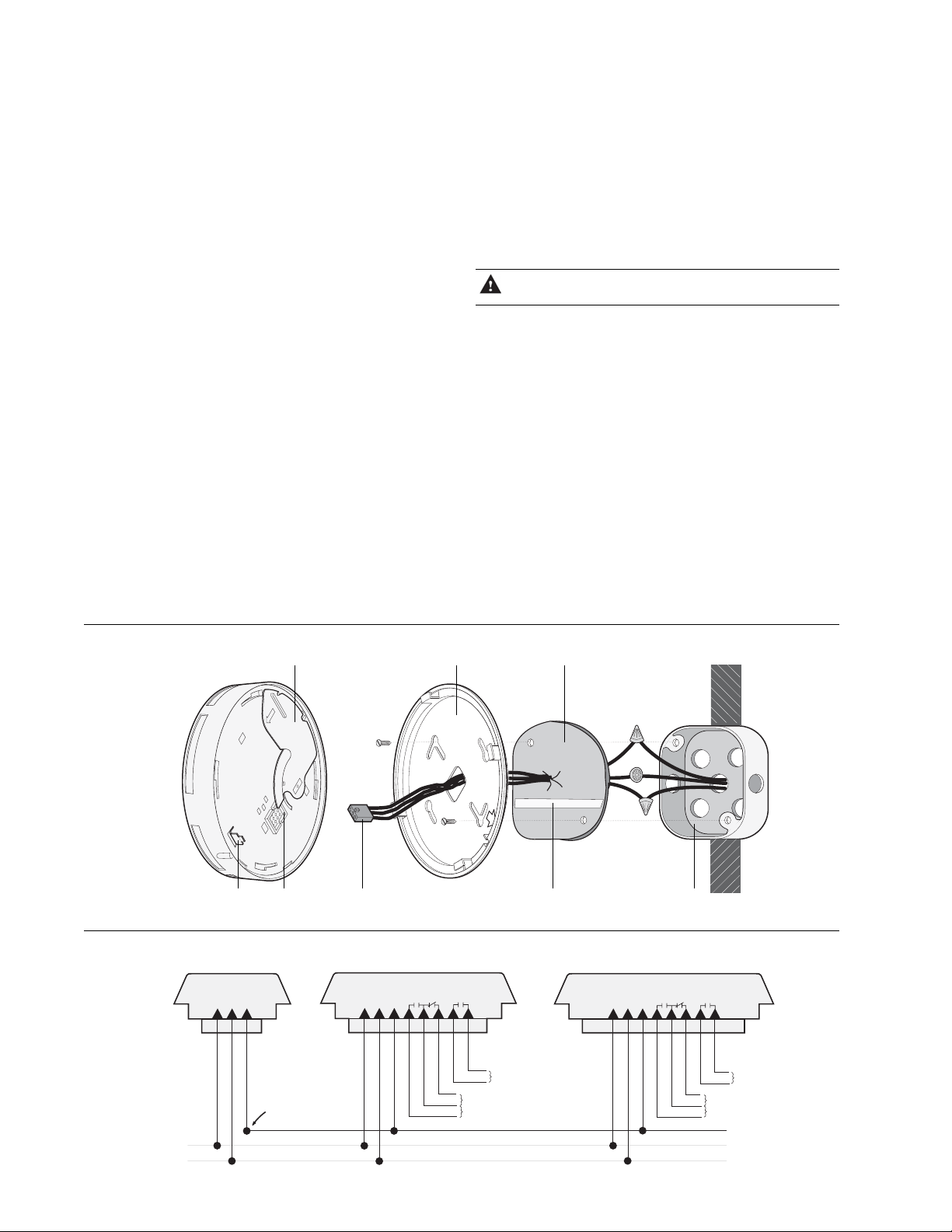
3. Using an NEC-approved method (see Wiring), attach the
connector assembly provided to the appropriate building
electric wiring (Figure 2).
4. Remove the backing from the adhesive strip (Figure 1) on
the back of the gasket.
5. Line up the straight edges of the gasket with the lines on the
back side of the mounting base and attach the gasket to the
mounting base.
Figure 1. Mounting the alarm
Figure 2. Wiring for tandem connections (maximum of 12)
Models:
320A / 350
black
white
Battery compartment
(350 models only)
SocketBase tamper tab
red
Connector
assembly
320ACC / 350CC
black
white
red
Mounting base Gasket
Models:
blue
orange
yellow
violet
violet
Form A relay
Adhesive strip Electrical box
Models:
320ACX / 350CX
black
white
red
blue
orange
yellow
violet
violet
Form A relay
Unswitched
120 VAC 60 Hz
power supply
Tandem bus
red
black (hot)
white (neutral)
Form C relay
Form C relay
To additional
smoke alarms
Page 2
2
ESL 320A/350 Series Smoke Alarms
Installation Instructions
6. Insert the connector assembly through the center hole in the
mounting base and gasket (Figure 1) and attach the base to
the mounting surface.
7. Plug the connector assembly into the socket on the back of
the smoke alarm (Figure 1). For 350 Series units, you must
install the battery and close the battery cover before the
connector can be attached.
8. To attach the alarm to its mounting base, line up the arrow
on the mounting base with the tab on the alarm (Figure 3).
Insert the alarm into the base an turn clockwise approximately 15 degrees. It should snap firmly into place.
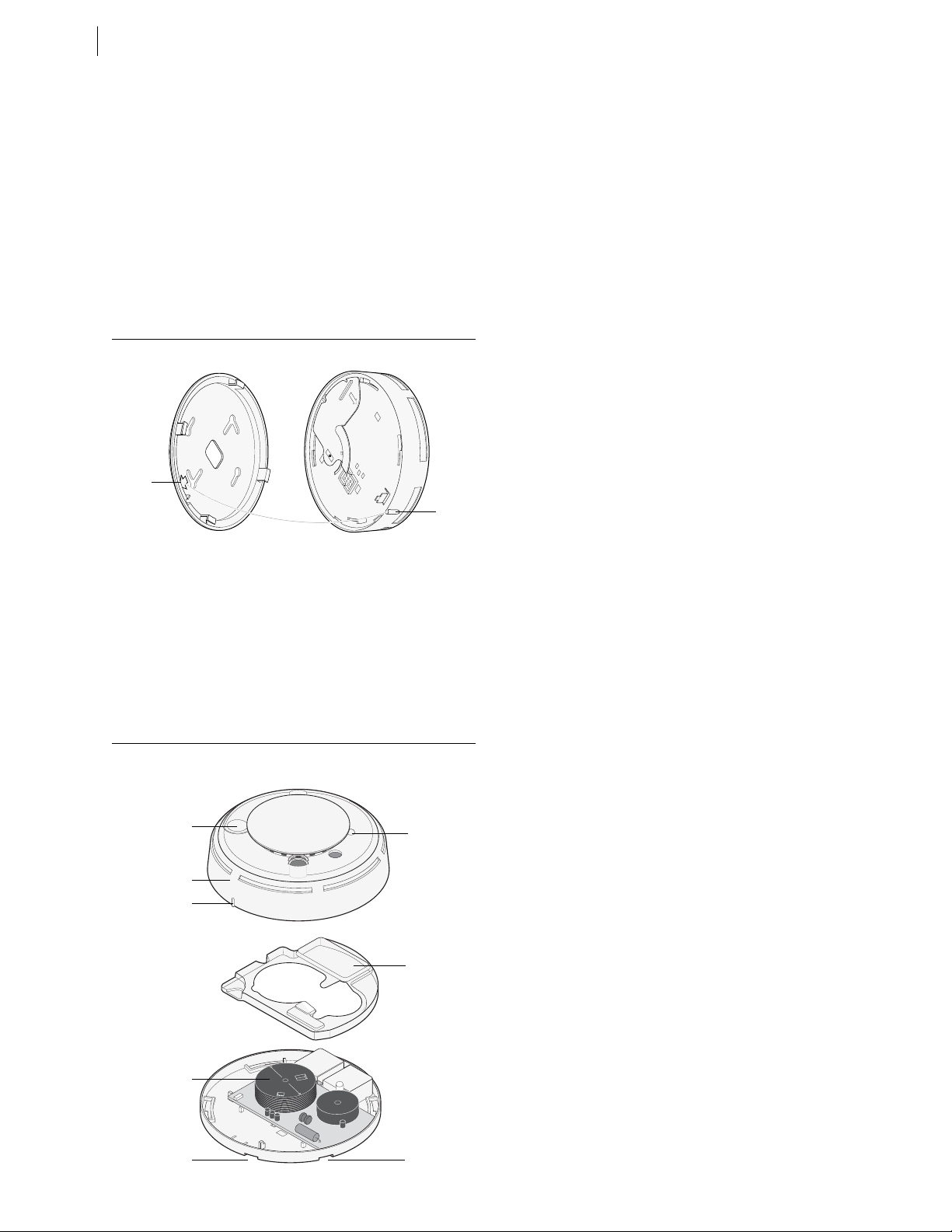
Figure 3. Arrow and tab alignment
Arrow
Tab
9. Apply AC power to the alarm.
10. To test the installation, press the test/silence button
(Figure 4) for approximately 1 second and release. The unit
should go into alarm, the LED should light steadily, and the
sounder should emit a temporal pattern. Testing of one
alarm will also cause alarms in tandem to sound. W e
recommend that you test each alarm individually.
11. Smoke-test the alarm. See Smoke test.
Figure 4. Alarm parts
T est silence button
Smoke alarm cover
Tab
Smoke chamber
LED
Clear plastic
cover
Wiring
Electrical wiring should be done by a licensed electrician. Use the
following guidelines when wiring the unit:
• Observe all applicable building code requirements.
Installation wiring shall conform with Article 76, Fire
Protective Signaling Systems, of the National Electrical
Code NFPA 70 1996 Edition. The tandem bus qualifies as a
power-limited circuit.
• Use 14 AWG cable or equivalent.
• Supply AC primary power either from a dedicated branch
circuit or the unswitched portion of a branch circuit also
used for power and lighting.
• When replacing a 320 Series alarm with a 320A/350 Series
alarm, use the existing connector.
• When replacing a 320ACX Series alarm, use the existing
320 Series connector and cap the white/red and white/blue
wires. Do not cap them together.
Single-station installation: Cap the red wire. Do not connect
it to any other circuit.
Tandem-station installation:
• Do not connect more than 12 alarms in a tandem circuit per
NFPA 72.
• Do not exceed 5,000 ft. (1524 m) for a tandem circuit.
• Use only 320 Series and 320A/350 Series alarms in tandem
connections.
Alarm test
The alarm power, sounder, and electronic module should be
tested monthly as follows:
Press the test/silence button (Figure 4) for approximately 1
second and release. The unit should go into alarm, the LED
should light steadily, and the sounder should emit a temporal
pattern.
If the alarm successfully goes into alarm, the unit has power and
the electronic module is functioning properly.
If the alarm fails the test, first check that power is present. If
power is present and it still fails, clean the alarm and replace the
smoke chamber. See Smoke chamber r eplacement.
Smoke test
T est smoke alarms in place annually using one of the following
methods:
• Use Smoke! in a can® (SM-200), a canned aerosol
simulated smoke and follow the directions on the can; or
• T est the alarm with smoke. Hold a smoldering punk or
cotton wick close to the smoke entry openings. Gently
direct smoke into the alarm for 20 seconds or until an alarm
is indicated.
Be sure to properly extinguish the smoke source after
testing! The alarm LED should light steadily and the sounder
should activate until the smoke clears or the text/silence button
(Figure 4) is pressed.
Slot
Slot
Page 3

3
LED status
The LED (Figure 4) indicates the status of the alarm as follows:
Flashing Flashes every 6 seconds to indicate normal
operation
On Detects smoke, sending an alarm
Off No power
When units are interconnected and one alarm activates, the LED
on units sensing smoke lights steadily, and the LED on the
others flashes every 4 seconds. This feature allows you to
identify which alarms have detected smoke.
T est/silence button
The alarm sounder activates a temporal pattern when smoke is
detected. To temporarily silence the sounder, press the test/
silence button (Figure 4)*. The sounder resumes if smoke is still
present.
* Only the initiating alarm can be silenced and only when
smoke obscuration is less than 4%/ft. During the silenced
period, the LED will continue to be steady, and the sounder
chirps every 4 seconds as long as smoke is present. If
connected in a tandem circuit, only the smoke alarm that
initiated the alarm can be silenced.
Attach/remove the alarm
To attach the alarm to its mounting base:
1. Plug the power connector into the back of the alarm. The
battery cover must be closed before the connector can be
attached.
2. Line up the arrow on the mounting base with the tab on the
alarm (Figure 3).
3. Insert the smoke alarm into the base and turn clockwise
approximately 15 degrees. It should snap firmly into place.
To remove the alarm from the mounting base:
1. Grasp the alarm and turn it counterclockwise approximately 15 degrees. The alarm should snap out of the
mounting base.
2. Unplug the power connector from the back of the alarm
and, if applicable, remove the batteries.
To remove the alarm from the mounting base when the
base tamper is used:
1. Insert a small screwdriver into the locking tab slot on the
side of the base (Figure 5) and press in while
simultaneoulsy turning the alarm counterclockwise 15
degrees. The alarm should snap out ot the mounting base.
2. Unplug the power connector from the back of the alarm
and, if applicable, remove the batteries.
Figure 5. Removing the alarm cover when a base tamper is used
Smoke chamber replacement
T o clean the smoke alarm and replace the smoke chamber (part
number 211), do the following:
1. Remove the alarm from its mounting base (see Attach/
remove the alarm). Unplug the power connector from the
back of the alarm and, if applicable, remove the batteries.
The alarm will activate if you remove the smoke chamber
while power is applied.
2. To remove the cover from the alarm base, open the battery
compartment and press the tab next to the indent (Figure
4). Lift the cover off and close the battery compartment.
3. Lift the clear plastic cover off the circuit board (Figure 4).
4. Press in on the sides of the smoke chamber (Figure 4) and
pull it straight out and away from the alarm. Discard the
smoke chamber.
5. Blow out or use a soft-bristled brush to remove dust and
dirt from the smoke chamber base.
6. Line the new smoke chamber up with the smoke chamber
base and snap down into place. Press firmly for proper
seating. The chamber should click twice into place.
7. Replace the clear plastic cover.
8. Replace the alarm cover by sliding the tab on the cover into
the two corresponding slots on the alarm base (Figure 4).
Gently press the cover to the alarm until they snap firmly
together.
9. Reattach the alarm to its mounting base. See Attach/remove
the alarm.
10 Test the alarm. See Alarm test and Smoke test.
Page 4

4
ESL 320A/350 Series Smoke Alarms
Installation Instructions
Maintenance
The 320A/350 Series smoke alarms are designed for easy field
service and when installed and used properly, they require
minimal maintenance.
T est alarms in place annually using smoke or canned aerosol
simulated smoke. See Smoke test.
Use the following indicators to determine when routine maintenance is required:
Indicator Maintenance required
Sounder chirping Replace battery (see Battery replace-
ment)
LED flashing rapidly Clean the alarm and replace the smoke
chamber (see Smoke chamber
replacement)
Battery replacement
The 350 Series smoke alarms provide a battery backup which
requires one 9-volt Duracell alkaline battery (provided). Battery
life varies depending on how often the backup is used. The
battery should be replaced yearly. If the alarm detects a low
battery condition, the alarm sounds a trouble chirp every 40
seconds until the battery is replaced.
Selecting a location
Selecting a suitable location is critical to the operation of smoke
alarms. This equipment should be installed in accordance with
the National Fire Protection Association’s (NFPA) Standard 72
(Figure 6).
Figure 6. Alarm location
A.
Dining
Room
B.
TV Room
Bedroom
Kitchen
Living Room
Dining
Room
Living Room
Bedroom
Bedroom
Bedroom
Kitchen Bedroom
Bedroom
C.
Bedroom
Living
Room
Basement
Required smoke alarms
Additional alarms for new construction
Bedroom
Dining
Room
A-11-8.3.a Where to Locate the Required Smoke Alarms in Existing
Construction.
The major threat from fire in a family living unit occurs at night when
everyone is asleep. The principal threat to persons in sleeping areas
comes from fires in the remainder of the unit. Therefore, a smoke
alarm(s) is best located between the bedroom areas and the rest of the
unit. In units with only one bedroom area on one floor, the smoke alarm(s)
should be located as shown in Figure 6 A.
In family living units with more than one bedroom area or with more than
one floor, more than one smoke alarm is required, shown in Figure 6 B.
In addition to smoke alarms outside of the sleeping areas, the installation
of a smoke alarm on each additional story of the family living unit,
including the basement, is required. These installations are shown in figure
6 C. The living area smoke alarm should be installed in the living room or
near the stairway to the upper level, or in both locations. The basement
smoke alarm should be installed in close proximity to the stairway leading
to the floor above. Where installed on an open-joisted ceiling, the alarm
should be placed on the bottom of the joists. The alarm should be
positioned relative to the stairway to intercept smoke coming from a fire
in the basement before the smoke enters the stairway.
Where to Locate the Required Smoke Alarms in New Construction.
All of the smoke alarms specified for existing construction are required
and, in addition, a smoke alarm is required in each bedroom.
Are More Smoke Alarms Desirable?
The required number of smoke alarms might not provide reliable early
warning protection for those areas separated by a door from the areas
protected by the required smoke alarms. For this reason, it is recommended that the householder consider the use of additional smoke alarms
for those areas for increased protection. The additional areas include the
basement, bedrooms, dining room, furnace room, utility room, and
hallways not protected by the required smoke alarms. The installation of
smoke alarms in kitchens, attics (finished or unfinished), or garages is not
normally recommended, as these locations occasionally experience
conditions that can result in improper operation.
Regulations pertaining to smoke alarm installations vary
from state to state. For more information, ontact your local
fire department or authority having jurisdiction (AHJ).
In addition to NFP A 72, use the following location guidelines to
optimize performance and reduce the chance of false alarms:
• Locate ceiling-mounted alarms in the center of a room or
hallway at least 4 inches (10cm) from any walls or
partitions.
• Locate wall-mounted alarms so the top of the alarm is 4 to
12 inches (10 to 31cm) below the ceiling.
• Locate in a suitable environment as follows:
- Temperature between 40 and 100°F (4.4 and 37.8°C)
- Humidity between 0 and 95% noncondensing
• Locate away from air conditioners, heating registers, and
any other ventilation source.
• Mount alarms on a firm permanent surface.
Smoke alarms are not to be used with detector guards
unless the combination has been evaluated and found
suitable for that purpose.
WARNING Smoke alarms CANNOT provide warnings
for fires resulting from explosions,
smoking in bed or other furniture, ignition
of flammable liquids, vapors and gases,
children playing with matches or lighters.
Failure to properly install, test, and
maintain a smoke alarm system may cause
it to fail resulting in loss of life and/or
property.
Page 5

5
Fire prevention and escape
The purpose of an early warning smoke alarm is to detect the presence of
fire in its early stages and sound an alarm giving the occupants time to
exit the premises safely.
Avoid Fire Hazards
No detection device can protect life in all situations. Therefore,
safeguards should be taken to avoid potentially dangerous situations as
follows:
• Do not smoke in bed.
• Do not leave children home alone.
• Never clean with flammable liquids such as gasoline.
• Properly store materials. A cluttered basement, attic, or other
storage area is an open invitation to fire.
• Use combustible materials and electrical appliances carefully and
only for their intended uses. Do not overload electrical outlets.
• Do not store explosive and/or fast burning materials in your home.
• Even after proper precautions have been taken, fires can start. Be
prepared.
In Case of Fire
In the event of a fire, do the following:
• Leave immediately. Don’t stop to pack or search for valuables.
• In heavy smoke, hold your breath and stay low, crawl if
necessary. The clearest air is usually near the floor.
• If you have to go through a closed door, carefully feel the door
and doorknob to see if undue heat is present. If they seem cool,
brace your foot against the bottom of the door with your hip against
the door and one hand against the top edge. Open it slightly. If you
feel a rush of hot air, slam the door quickly and latch it. Unvented
fire tends to build up considerable pressure. Be sure all members of
the household realize and understand this danger.
• Use your neighbor’s phone or a street fire alarm box to call the fire
department. The job of extinguishing the fire should be left to the
professionals.
Be Prepared
Practice the following steps to prepare you and your family in the event
of a fire:
• Perform fire drills regularly. Use them to assure recognition of an
alarm signal.
• Draw a floor plan and show two exits from each room. It is
important that children be instructed carefully, because they tend to
hide in times of crisis.
• Establish one meeting place outside the home. Insist that everyone
meet there during an alarm tol eliminate the tragedy of someone
reentering the house for a missing member who is actually safe.
• If you have children and/or physically challenged people residing in
your household, use window decals to help emergency personnel
identify the sleeping quarters of these individuals.
Limitations of smoke alarms
The 320A/350 Series smoke alarm is designed to be connected to the
electrical systm of your home and requires electric power to operate. The
smoke alarm will not operate and the alarm will not sound if, for any
reason, the power source is cut off. In the case of an electrical fire, for
example, the power source may be cut off before the alarm can funciton,
and the alarm will not sound. If this smoke alarm is connected to a
separate dedicated circuit it should work more reliably than devices
connected to circuits serving other appliances, but even in dedicated
circuits it can fail. It is advisable to install a battery-powered smoke alarm
as a backup system. All smoke alarms should be regularly and
thoroughly inspected and tested (at least once per month) to help
maintain continued operability.
Smoke alarms are a significant help in reducing loss, injury and
even death. However, no matter how good a detection device is,
nothing works perfectly under every circumstance and we must
warn you that you cannot expect a smoke alarm to ensure that you
will never suffer any damage or injury.
Limited warranty
The ESL 320A/350 Series is a product of the Security business of GE
Infrastructure. The manufacturer warrants this smoke alarm to be free
from defects in material and workmanship under conditions of normal
use for a term of 3 years from the date of manufacture.
During the warranty period, if the product or any of its components
becomes defective, it will be repaired or replaced without charge.
Out-of-warranty units will be repaired at the discretion of the manufacturer, if not, a card will be forwarded to the customer suggesting a
replacement unit and the cost of that unit. This warranty does not apply
to units which have been subject to abuse, misuse, negligence or
accident, or to which any modifications, alterations or repairs have been
made or attempted. This warranty is extended only to the original
purchaser of the smoke alarm and may be enforced only by such
person. During the warranty period, if the alarm or any warranted
components thereof becomes defective, at the manufacturer’s
discretion, it will be replaced or repaired without charge if returned in
accordance with the following instructions:
Obtain a Return Authorization Number by calling 1-888-437-3287, then
carefully pack the unit it in a well padded and insulated carton and
return, postal charges prepaid to:
Customer Service RMA#
GE Security
12345 SW Leveton Drive
Tualatin, OR 97062-9938
A note should be included advising the nature of the malfunction. Care
must be exercised in the proper packing of alarms returned under this
warranty as the manufacturer will not be responsible for warranty repairs
to equipment damaged because of improper packing.
The above warranty is in lieu of all other express warranties, and
implied warranties of merchantability and fitness for a particular
purpose are limited in duration for a period of 3 years from the
date of manufacture. Under no circumstances shall manufacturer
be liable to the purchaser or any other person for incidental or
consequential damages of any nature, including without limitation
damages for personal injury or damages to property, and however
occasioned, whether alleged as resulting from breach of warranty
by manufacturer, the negligence of manufacturer or otherwise.
Manufacturer’s liability will in no event exceed the purchase price
of the product. Some states do not allow limitations on how long
an implied warranty lasts, or the exclusion or limitations of
incidental or consequential damages, so the above limitations and
exclusions may not apply to you. Unless a longer period is
required by applicable law, any action against Manufacturer in
connection with this smoke alarm must be commenced within one
year after the cause of action has occurred.
No agent, employee or representative of the Manufacturer nor any other
person is authorized to modify this warranty in any respect. Repair or
replacement as stated above is the exclusive remedy of the purchase
hereunder. This warranty gives you specific legal rights and you also
have other rights which vary from state to state.
Page 6

6
ESL 320A/350 Series Smoke Alarms
Installation Instructions
Specifications
Voltage 120 VAC at 60 Hz
Current 130 mA max.
Sensitivity 0.83%/ft. min. to 2.46%/ft. max.
Operating temperature 40 to 100°F (0 to 55°C)
Operating humidity 0 to 95%, noncondensing
Sounder 85 dB at 1 0 ft. (305 cm)
Relay time delay 5 seconds (nominal)
Contacts 1 A at 30 VDC, 120 VAC resistive
Dimensions 6.0 in. (15.2 cm) diameter
2.0 in. (6.4 cm) deep
Weight 9.6 oz.
Battery 9 V akline Duracell, type MN1604
Listings UL 217, CSFM, MEA
Product ordering
Product Description
320A/350 120 VAC photoelectric alarm with pigtail
connector. (350 model includes 9 V
battery backup.)
320ACC/350CC 120 VAC photoelectric alarm with pigtail
connector, form A and form C relays
that do not operate from the tandem
circuit, they must detect smoke.
(350CC model includes 9 V battery
backup.)
320ACX/350CX 120 VAC photoelectric alarm with pigtail
connector, form A and form C relays
that operate from the tandem circuit
and when smoke is detected. (350CX
model includes 9 V battery backup.)
Accessories
SM-200 Smoke! in a can® (canned smoke) for
functional testing of smoke detectors
SM-EXT1 Extension tube for Smoke! in a can®
211 Replacement smoke chambers (set of
10)
Certain items in the installation instructions are protected under
one or more of the following patents: 5,546,074; 5,798,701;
5,821,666; 6,756,906.
12345 SW Leveton Drive
GE Security
Tualatin, OR 97062
Tech Support: 888-437-3287
www.gesecurity.com
15814C / February 2005
 Loading...