

Page 1
GE
Security
250-CO Carbon Monoxide
Detector Installation Sheet
Description
The 250-CO Carbon Monoxide Detector monitors the levels of CO
gas and gives early warning when potentially dangerous levels
exist. It does not detect fire, smoke, or any other gas.
The 250-CO provides a multicolored LED and a sounder to indicate
the detector status. Use Table 1 to determine the status of the
detector. The detector automatically resets when CO is no longer
detected.
The 250-CO Carbon Monoxide Detector is intended for indoordwelling unit applications in both residential and commercial
occupancies, including single/multiple family residential
occupancies, hotel rooms, dorm rooms, and other areas approved
by the authority having jurisdiction (AHJ).
The 250-CO detector can connect to either UL 985 (Household Fire
Warning) or UL 864 (Commercial Fire) control panels. It is not
intended for use in industrial applications such as gasoline
refineries or parking garages, which require different listings.
The 250-CO detector is not intended to meet the requirements of
CAN/CSA-6.19 (Residential Carbon Monoxide Alarming Devices).
Please check with the local codes concerning the applicability of
this requirement for each installation.
The 250-CO detector has an optional adapter mounting plate. To
purchase the plate order P/N 250-COPLT-5PKG.
The built-in sounder is a supplementary alarm notification device.
The control panel is considered the primary alarm notification
device.
WARNING: Use only with a UL Listed control panel that recognizes
different alarm types (fire, burglary, CO, etc.) and that provides a
distinct notification for each type.
Sensor end of life indicator: The detector uses both a flashing
green LED and intermittent sounder chirps to indicated that the
detector needs replacing. The detector also signals a trouble
condition when the CO sensor reaches end-of-life. When
connected to a UL Listed control panel, the trouble relay can
report a trouble condition locally at the panel and optionally at the
central station, if the system is monitored.
Common trouble relay: The trouble relay opens to indicate a
trouble condition upon lost power, CO sensor cell trouble, or cell
end-of-life.
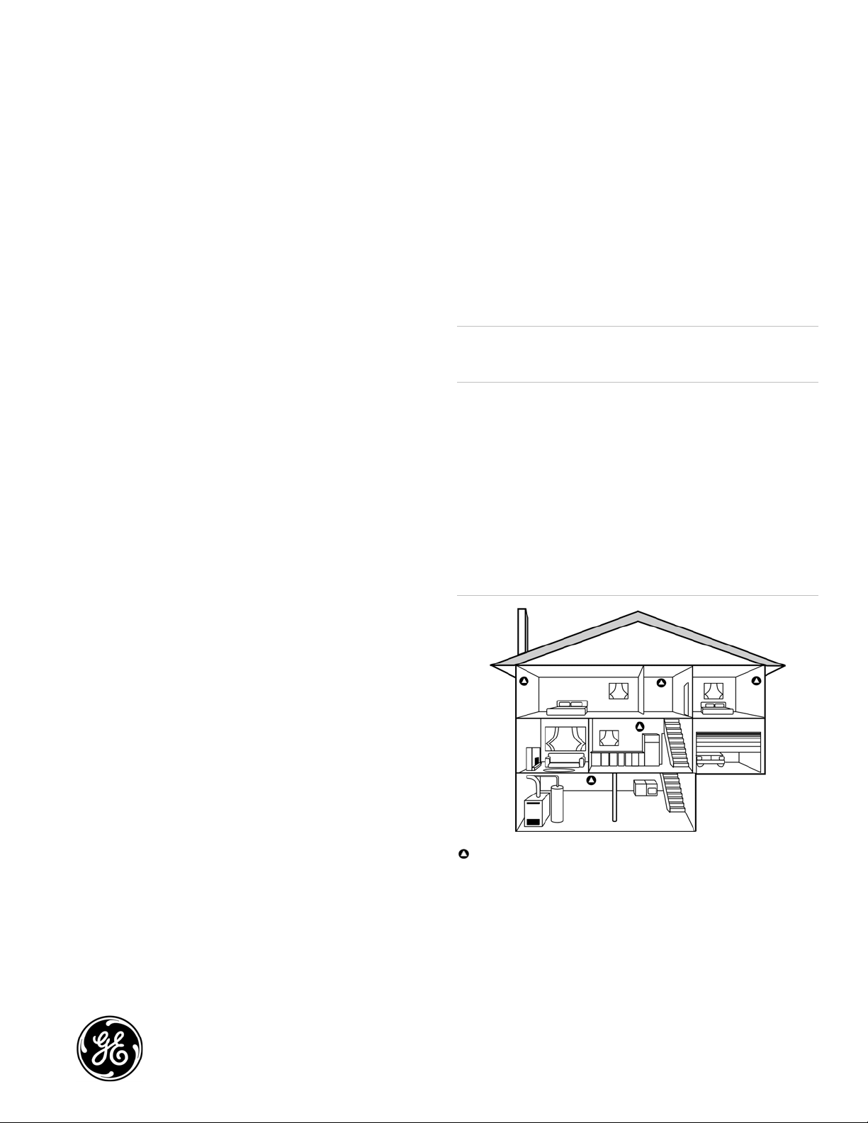
Figure 1: Recommended CO detector locations
Features
Test/hush button: Use the test/hush button to test the alarm and
silence an activated alarm. Pushing the test/hush button silences
the integral sounder for five minutes. The red alarm light stays on,
and if CO is still present after five minutes, the detector once again
sounds in the temporal-four pattern. The hush feature does not
operate at CO levels above 350 ppm (parts per million).
Distinct 85 dB temporal-four sounder alarm: The 85 dB
temporal-four sounder provides a distinctive alarm notification
that is easy to differentiate from smoke alarm notification devices.
The alarm beeps four times, pauses five seconds and then repeats
the pattern.
© 2010 GE Security, Inc.
CO detector locations
P/N 1061018 • REV D • ISS 10FEB10
1 of 6
Page 2

Table 1: Detector status indications
Status LED Sounder Description
Safe air Green, 1 pulse every 15
seconds
Alarm Red, pulses with
sounder
Trouble Amber, pulses with
sounder
End of sensor life Amber, pulses with
sounder
Loss of power No LED No sounder Activates the trouble relay.
Detector locations
Selecting a suitable location is critical to the operation of CO
detectors. Install the 250-CO in accordance with NFPA 720
Standard for the Installation of Carbon Monoxide (CO) Detection
and Warning Equipment. Place wall-mounted detectors at least
No sound The detector has power and is functioning properly.
Sounds four rapid beeps
every five seconds or every
minute after five minutes in
the alarm state
Sounds one rapid beep
every 45 seconds
Sounds one rapid beep
every 15 seconds
Dangerous levels of CO are present. Evacuate the premises.
Press the test/hush button to silence the sounder for five minutes.
Activates the alarm relay. If connected, the alarm panel activates.
There is a problem with the detector and the detector is not working
properly. Contact the service company to correct the trouble and
replace the detector, if necessary.
Press the test/hush button to silence the detector for nine hours.
Activates the trouble relay.
The sensor is no longer working. Replace the detector as soon as
possible.
Press the test/hush button to silence the detector for 36 hours.
Activates the trouble relay.
Notes
• Do not install CO detectors until after final construction
cleanup (unless otherwise specified by the AHJ).
• Leave this installation sheet with the owner/user of this
carbon monoxide (CO) detection equipment.
5 ft. (1.5 m) up from the floor. For ceiling mounted applications,
place the detector at least 1 ft. (0.3 m) from any wall.
The recommended CO detector locations are:
• Within 10 ft. (3 m) of all sleeping areas, including areas such
as hotel rooms and dorm rooms.
The 250-COPLT adapter plate
Use the 250-COPLT adapter plate when replacing a 240-COe with
a 250-CO to cover the footprint of the 240-COe. For example, use
the plate to cover different wall colors.
• In a suitable environment: areas with a temperature range of
32 to 104°F (0 to 40°C) and with a relative humidity range of 0
to 90% noncondensing.
• In residential dwellings, locate detectors in every bedroom,
within 10 ft. (3 m) of sleeping areas, and on each level. At a
minimum, place one detector outside the sleeping areas. See
Figure 1 on page 1.
The recommended CO detector locations in commercial
occupancies are:
• On every habitable level of the building based on an
engineering evaluation considering potential sources and
Installation
The 250-CO Carbon Monoxide Detector is a four-wire device
designed to use a Class 2 output from a UL 985 or 864 Listed
control panel or auxiliary power supply.
All wiring must conform to the NFPA 70 National Electric Code, UL
2075 Standard for Gas and Vapor Detectors and Sensors, NFPA 720
Standard for the Installation of Carbon Monoxide (CO) Detection
and Warning Equipment, and applicable codes. Use 14 to 22 AWG
wire.
migration of carbon monoxide
• In any area required by local building codes, legislation, or
authorities having jurisdiction
• On a firm, permanent surface
Do not install the CO detector:
• Within 10 ft. (3 m) of a fuel-burning appliance
• Near air conditioners, heating registers, or any other
WARNINGS
Connect the CO detector only to a zone dedicated exclusively to
CO detection and that is monitored 24 hours a day. Do not
connect to an initiating circuit with fire or security devices.
Failure to properly install, test, and maintain a CO detector may
cause it to fail, potentially resulting in loss of life.
ventilation source that may interfere with CO gas entering the
detector
• Where furniture or draperies may obstruct the airflow
• In a recessed area
To install the detector (without the adapter plate):
1. Run the 250-CO detector wiring to the detector location.
2. Carefully remove the cover from the detector using a small,
flat screwdriver blade in the slot on the left side of the
detector cover.
2 of 6 P/N 1061018 • REV D • ISS 10FEB10
Page 3

3. The mounting hole pattern is for single-gang spacing. Use the
base for a template to mark the two screw hole locations on
the mounting surface or mount on a single-gang box (not
provided).
4. Install two screws on the marks. If necessary, use wall
anchors.
5. Line up the base with the screws, pull the wires through the
square holes, and slide the base down the screws to the wall.
For surface wiring, pull the wires through the wiring channel
at the bottom of the base.
6. Strip 3/8 in. of insulation from each wire.
7. Determine the correct wiring (see "Wiring" and Figures 3 to 5
below) and insert the wires under the appropriate screw
terminals.
8. Tighten both screws to secure the base to the wall.
9. Replace the detector cover.
10. Apply power. The LED should flash green for approximately
four seconds and then pulse green.
11. Test per the testing instructions below.
To install the detector using the adapter plate:
1. Run the 250-CO detector wiring to the detector location.
2. Using the 250-COPLT wall plate for a template, trace the
perimeter of the two square holes on the mounting surface.
Also mark the two screw locations.
3. Cut out the two square holes.
4. Install two screws on the marks. If necessary, use wall
anchors.
5. Mount the wall plate but do not fully tighten down the screws.
6. Carefully remove the cover from the detector using a small,
flat screwdriver blade in the slot on the left side of the
detector cover.
7. Pull the wires through the square holes on both the wall plate
and the 250-CO base. Then slide the detector base over the
screws.
8. Strip 3/8 in. of insulation from each wire.
9. Determine the correct wiring (see "Wiring" and Figures 3 to 5
below) and insert the wires under the appropriate screw
terminals.
10. Tighten both screws to secure the base to the wall plate.
11. Replace the detector cover.
12. Apply power. The LED should flash green for approximately
four seconds and then pulse green.
13. Test per testing instructions below.
Figure 2: Screw terminals
3
1 2
4
1. Sounder
2. Sensor
3. Alarm relay
4. Terminals ”−” and “+” are for power; terminals “NC” and “C”
are the common trouble relay shown in the normal state for
this detector
Testing
Test the detector after installation and regularly to verify that it is
functioning properly.
To test the CO detector:
1. To test the alarm and trouble relay panel connection, first
notify all persons and facilities that receive an alarm and
trouble signals (to prevent unnecessary response).
2. Momentarily press the test/hush button to start a test cycle.
During the test cycle the detector should beep four times with
a five second pause, then beep four more times. The LED
should flash red at each sounder beep. At the end of the test
cycle, the green LED illuminates for approximately four
seconds.
3. Momentarily disconnect the power supply from the detector
and verify that the common trouble relay opens.
4. Verify that the panel reacts correctly to the alarm relay
activation.
5. If the detector fails the test, verify that the power leads are
connected properly, wait briefly then try again. If the detector
fails again, replace it.
Maintenance
Clean the detector as needed with a clean cloth (either dry or
dampened with water) to keep openings free from dust and dirt.
Test the detector regularly.
Do not paint the detector or expose it to cleaning solutions.
Notification
Notification of carbon monoxide detectors should be consistent
with NFPA 720 and the local AHJ. Notification zones should be
consistent with the emergency plan for the protected premises.
P/N 1061018 • REV D • ISS 10FEB10 3 of 6
Page 4

Wiring
There are three typical wiring configurations:
• Single device and single zone (Figure 3)
• Multiple devices in a single zone (Figure 4)
• Multiple devices with separate alarm and trouble zones
(Figure 5)
CO detector replacement
The 250-CO Carbon Monoxide Detector has a long-life carbon
monoxide electrochemical sensor. Replace the detector with a
new 250-CO detector after six years from the date of manufacture
or when an audible and visible annunciation occurs signaling endof-life.
To silence the detector, push the test/hush button
Figure 4: Multiple devices, single zone configuration
1
Figure 3: Single device, single zone configuration
1
PWR
PWR
1. Alarm IDC (NO)
2. End-of-line device (provided by the life safety system)
Note: Relay is shown in the normal state for this detector
2
2
PWR
PWR
1. Alarm IDC (NO)
Note: Relay is shown in the normal state for this detector
Figure 5: Multiple devices, separate alarm, trouble zone configuration
1
2
PWR
PWR
1. Alarm IDC (NO)
2. Supervisory IDC (NC)
Note: Relay is shown in the normal state for this detector
2. End-of-line device (supplied by life safety system)
3
3
3. End-of-line device (supplied by life safety system)
4 of 6 P/N 1061018 • REV D • ISS 10FEB10
Page 5

General limitations of CO detectors
CO detectors require a source of power to work. Verify that the
green LED on the detector is flashing at all times. Since this unit is
powered by a control panel, it may not operate during a power
failure or if the control panel is disabled.
WARNING: This product is intended for use in ordinary indoor
locations of family living units. It is not designed to meet
compliance with Occupational Safety and Health Administration
(OSHA) commercial or industrial standards.
The 250-CO detector is not intended to meet the requirements of
CAN/CSA-6.19 (Residential Carbon Monoxide Alarming Devices).
Please check with the local codes concerning the applicability of
this requirement for each installation.
People with special medical problems should consider using
specialized detection devices with less than 30 ppm (parts per
million) alarming capabilities.
This detector only indicates the presence of carbon monoxide gas
at the detector. CO may be present in other areas. Anything
preventing CO from reaching the detector, such as closed doors,
could delay or prevent detector activation.
If the unit is in trouble or at the end of its life, it may not sense CO
and cannot be relied upon to monitor carbon monoxide levels.
CO detectors are not smoke detectors: This detector is designed
to detect CO from any combustion source. It is not designed to
detect smoke, fire, or any other gas.
CO detectors may not be heard: A sound sleeper, or someone
who has taken drugs or alcohol, may not awaken if the detector is
installed outside a bedroom. Normal noise due to stereos,
television, etc. may also prevent the detector from being heard if
distance or closed or partly closed doors muffle the sounder. This
unit is not designed for the hearing impaired.
CO detectors are not a substitute for life insurance: Though
these detectors will warn against increasing CO levels, we do not
warrant or imply in any way that they will protect lives from CO
poisoning. They should only be considered as an integral part of a
comprehensive safety program.
Specifications
Input voltage 12 or 24 VDC supplied by control panel or
resettable auxiliary power supply
Current consumption
Normal
Alarm
Alarm relay
Type
UL rating
Common trouble relay
Type
UL rating
CO alarm level 70 ppm/60 to 240 minutes
Sounder 85 dB
Compatible control panel UL 985 or UL 864 Listed
Compatible electrical box North American 2-1/2 in. (64 mm) deep single-
Wire size 14 to 22 AWG (0.25 to 2.0 mm²)
Dimensions (W x L x D)
Detector
Adapter plate
Weight
Detector
Adapter plate
Color White
Operating environment
Temperature
Relative humidity
Altitude
20 mA
40 mA (75 mA in test)
150 mA at 33 VDC
Form C
Zone
150 mA at 33 VDC
Normally opened held closed with power
applied
Common
gang
3.1 x 4.6 x 1.3 in. (7.8 x 11.7 x 3.2 cm)
4.5 x 6.5 x 0.2 in. (11.4 x 16.5 x 0.5 cm)
4.7 oz. (133 g)
1.6 oz (46 g)
32 to 104°F (0 to 40°C)
0 to 90%, noncondensing
Less than 6,000 ft. above sea level
Regulatory information
Manufacturer GE Security, Inc.
HQ and regulatory responsibility:
GE Security, Inc., 8985 Town Center Parkway,
Bradenton, FL 34202, USA
Year of
manufacture
UL rating 12 VDC, 24 VDC
North American
standards
The first two digits of the product serial number
(located on the product identification label) are the
year of manufacture.
UL 2075
This detector has been evaluated to the CO alarm
sensitivity limits of UL 2034.
Contact information
For contact information see our Web site: www.gesecurity.com
P/N 1061018 • REV D • ISS 10FEB10 5 of 6
Page 6

6 of 6 P/N 1061018 • REV D • ISS 10FEB10
 Loading...