

Page 1
GERUS
Bedienungsanleitung
zur Gerupress Hochdruckpumpe HP26
Operating manual
for Gerupress high pressure pump HP26
11.49015 – 0105
Version: 2.0
Datum: 19.07.2016
GERUS Apparatebau GmbH & Co KG
Engelschalkstrasse 16
Seite 1 von 8
Page 2
GERUS
EC-Declaration of Conformity
We, the company
GERUS Apparatebau GmbH&CO.KG
Engelschalkstrasse 16,
86316 Friedberg, Germany,
declare hereby that the following described
machine in its conception, construction
and form put by us into circulation is
in accordance with all the relevant essential
health and safety requirements of the
following EC directives.
EG-Konformitätserklärung
Wir, die Firma
GERUS Apparatebau GmbH&CO.KG
Engelschalkstrasse 16,
86316 Friedberg, Deutschland,
erklären hiermit, dass die nachfolgend
bezeichnete Maschine aufgrund ihrer
Konzipierung und Bauart sowie in der von
uns in Verkehr gebrachten Ausführung den
einschlägigen Sicherheits- und Gesundheitsanforderungen den nachfolgenden
angeführten EG-Richtlinien entspricht.
Bezeichnung der Maschine/ description of the machine
Druckluftbetriebene hydr. Hochdruckpumpe/ airdriven hydr. high pressure pump
HP26 -
Maschinenrichtlinie/ machinery directive
2006/42/EG 2006/42/EC
Angewandte harmonisierte Normen/ applied harmonized standards
Friedberg, 13.06.2014
Dipl. Ing. Rudolf Schroll
Geschäftsführer/ business manager
Bevollmächtigter techn. Dokumentation/ authorized person for techn. documentation
Typ/ type
GERUPRESS HP26
Serien-Nr./ serial-no.
EMV-Richtlinie/ EMC directive
2014/30/EU
EN12100:2011, EN 60204
Franz Lulei
Seite 2 von 8
Page 3
GERUS
REACH Erklärung REACH Declaration
Wir, die Firma We, the company
GERUS Apparatebau GmbH&CO.KG GERUS Apparatebau GmbH&CO.KG
Engelschalkstrasse 16, Engelschalkstrasse 16,
86316 Friedberg, Deutschland, 86316 Friedberg, Germany,
erklären hiermit, dass wir als Hersteller declare hereby that as a manufacturer of
von Maschinen und Werkzeugen zur machines and tools for overhauling and
Überholung und Instandsetzung von maintenance of large bore engines we
Großmotoren von der Verordnung nur are only concerned by the regulation as
als nachgeschalteter Anwender betroffen downstream user and, therefore, we are
sind und daher nicht zur Registrierung not bound to register or pre-register.
und Vorregistrierung verpflichtet sind.
Beim Gebrauch unserer Maschinen werden Under normal use of our machines, no
Keine Schadstoffe im Rahmen von Artikel harmful substances within the scope of
7.1 und 7.2 der Verordnung freigesetzt Article 7.1 and 7.2 of the regulation are
released.
Ort und Datum/ place and date
Friedberg, 17.04.2015
Name und Position des Unterzeichners/ name and position of signer
Dipl. Ing. Rudolf Schroll
Geschäftsführer/ business manager
Seite 3 von 8
Page 4

GERUS
Inhaltsverzeichnis / Index of Contents
1 Instructions ........................................................................................... 5
2 Instructions for use ................................................................................ 6
2.1. How to test a high pressure pump to see if it works ................................................. 6
2.2. How to work with the high pressure pump ................................................................ 6
3 Risk analysis ......................................................................................... 7
4 How to exchange the oil at the high pressure pump .............................. 7
5 Technical data ...................................................................................... 8
6 After-Sales service and self-help ........................................................... 8
Seite 4 von 8
Page 5
GERUS
K
F
E
H
M
D
A
I
G
C
B
L
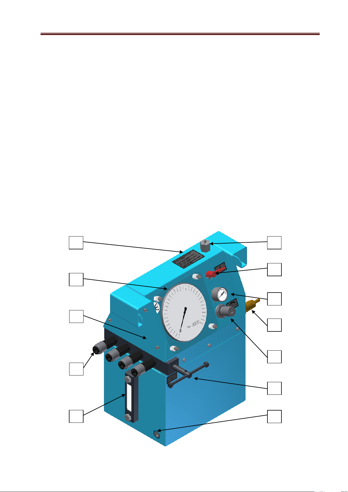
1 Instructions
The GERUPRESS provides high static pressures for using them in combination with hydraulic
tightening device. Because of its specification the GERUPRESS is not suitable supporting large
delivery ranges under high pressure. Neither the capacity of the oil pump nor the range of hydraulic
oil do not allow operating under these circumstances. In its specified application, the GERUPRESS
works exclusively with the medium compressed air.
The function of the GERUPRESS is based on a proportional working oil pump. The absolute
maximum output pressure is secured by a security valve (adjustable) in the low pressure circle (cf.
risk analysis).
For operating, the compressed air (pressure < 15 bar) have to be connected to the GERUPRESS,
the gauges have to be checked and the operating lever have to be shift (operating). Now, the pump
starts working until the adjusted value of the output pressure has been reached.
It is possible to adjust the output pressure by the pressure limitation valve until either the requested
value is pointed on the gauge or the maximum pressure of 2500 bar is reached. For set off (high
pressure is no longer necessary) the operating lever have to be shift back in “1”-position. For
ventilation of ducts the manual ventilation valve has to be opened.
Disconnect high pressure tubes only while ventilation valve open.
Seite 5 von 8
Page 6

GERUS
2 Instructions for use
2.1. How to test a high pressure pump to see if it works
1. Check if the pressure gauges F and I are intact and control the position of the indicators.
Both indicators should be on zero.
2. Control the oil level (by locking at oil level controller E).
3. If the oil level is too low, fill in oil and follow these instructions:
3.1. Choose the quality of the oil according to the instructions on sign H.
3.2. Open the oil admission socket D to fill in the oil by turning to the left.
3.3. Fill in the oil until the oil level controller E indicates that the tank has been filled up three
quarters (¾).
3.4. Now close the oil admission socket D by turning it to the right.
4. Close the pressure relief valve B and turn it to the right as far as it will go.
5. Now turn lever A (=start lever) into position II.
6. Connect the compressed air-tube to the compressed-air connection G.
BE CAREFULL: never use more than the maximum of 15 bar!
7. Pull and turn the pressure control valve C to the right as far as it will go (until you feel a
resistance).
8. Check the air pressure on the pressure gauge I (There should be an air pressure of at least
6 bar).
9. Put start lever A into position I.
10. The pump starts working and should build up a pressure of up to 2.500 bar (if it doesn’t,
please check the air pressure).
11. When the oil pressure gauge F shows a pressure of 2.500 bar turn lever A back into position
II.
12. The pressure shown on oil pressure gauge F shouldn’t fall. This means that the pump is in
working order.
13. Open the relief valve B by turning it to the left.
14. The pressure shown on oil pressure gauge F now drops to 0 bar.
2.2. How to work with the high pressure pump
Start again with position 1. to 6.
Now pull and turn on the relief valve C to get the right oil pressure: 2 bar air pressure ≈ 500 bar oil
pressure. Then connect the high pressure tubes to the hose connection K.
Continue with position 9. to 14. Remove the high pressure tubes from the hose connection K when
you are finished.
BE CAREFULL: Hydraulic tubes can only be attached or removed if the relief valve E is
open. The oil pressure gauge A has then dropped to 0 bar.
Seite 6 von 8
Page 7

GERUS
3 Risk analysis
a) The oil pump is working as pressure translator, thus improper output pressures cannot be
reached because the lower operating pressure is limited.
b) Improper absolute output pressures will be lock out by a additional pressure reducing valve
in the low pressure circle.
c) Leaks or duct cracks in the high pressure circle including no health risks for operators.
d) Duct crack cause a breakdown of the output pressure.
e) Is the determined output pressure not available after a short time, a damage of the
GERUPRESS is probably occurred. In this case, put the gadget out of operation, disconnect
the connect air tubes. Otherwise the gadget will get dirty by hydraulic oil.
f) Pay attention while closing of the cover. Prohibit
• damaging (operating level in „1“, cover cannot be closed)
• wounding
g) Sufficient lubrication of the oil pump and providing with hydraulic oil is ensured by mounting
the pump into the oil tank. In case of a pump leakage, the gadget and the operator is
protected by the casing of the tank.
BE CAREFULL: Disconnect high pressure tubes only while ventilation valve open.
4 How to exchange the oil at the high pressure pump
Oil can be removed by opening the oil screw L and by lifting the pump on the opposite side of the
pump.
BE CAREFULL: the oil starts running out as soon as you have loosened the screw!
Use oil admission socket D to fill in the oil.
Oil level gauge E indicates how much oil you have filled in. The pump should be filled up to three
quarters (¾).
BE CAREFULL: Only use oils with the following specifications:
oil quality: anti-corrosion oil,
viscosity approx. 13 mm² / s = cSt / 20° C
We advise you to exchange the oil every three years because otherwise the pump might be
damaged due to residues of dirt.
Seite 7 von 8
Page 8

GERUS
5 Technical data
Air pressure (pB): 1,5 – 7,0 bar (pBmax = 15,0 bar)
Output pressure (pA): 2500 bar (max. pressure for permanent
operating)
Test pressure (pprüf): 2500 bar (test operating)
Gadget connections:
Output pressure: CEJN high pressure coupling
(type series 125)
Air pressure: compr. air conn. 9mm
Masses:
empty: 30,00 kg
filled: 40,00 kg
Dimensions:
height: 550 mm
length: 431 mm
width: 315 mm
Volume of tank: 10 l (dm³)
Performance and consumption of air:
0,6 m³/min for 6 bar compr. air ≡ 1,5 dm³/min for 1000 bar
6 After-Sales service and self-help
If the pressure at oil pressure gauge F doesn’t remain constant and drops (as described under
point 12., the pump is not air-tight or the decompression valve B is not fully closed.
In most cases, this is due to the fact that the O-rings are old/worn-out. It is possible to exchange
the O-rings. A complete set of O-rings (article-no. 11.49015-0067) is enclosed in the pump.
The packet of spare parts can be taken out by opening the front plate M. An explosion drawing of
the pump is also included.
It is recommendable to have the pump overhauled by its manufacturer
GERUS APPARATEBAU GmbH & Co. KG,
Engelschalkstraße 16
D-86316 Friedberg
Tel.: 0049 – (0)821 - 588 662-0
FAX: 0049 – (0)821 - 588 662-10
E-Mail: [email protected]
Seite 8 von 8
 Loading...