

Page 1

1XLp Installation & Configuration, June 2010
GERBERSERVICE
XLp GERBERplotter Family
Installation & Configuration
Presented by Ronny Sprangers
Page 2

2XLp Installation & Configuration, June 2010
Training Outline
• Overview of XLp Plotter
• Hardware Installation
• Software Installation
• Gerber Device Configuration
• The XLp Interface
• Calibrations
• Maintenance
Page 3

3XLp Installation & Configuration, June 2010
Overview
• The XLp 50/95 plotters are easy to use, wide format,
inkjet plotters that provide features such as high
reliability, accuracy and low operation costs.
• They have a multi-functional operator panel with
large LCD display
• They are compatible with existing Gerber products
and they offer a Windows based graphical interface
for intuitive control and status messaging.
• Like the Infinity range, the XLp is also based on the
HP 51645 inkjet cartridge.
Page 4

4XLp Installation & Configuration, June 2010
Overview
1.Nip Bar Lever : This
lever controls the Nip
Bar and Pinch Rollers.
2.Front Cover
3.Control Panel : Allows
the operator to perform
manual functions.
Currently only English
and Chinese
4.Feed Roll Bar
5.Paper Take-Up Bar : The
paper can be dropped
onto the floor or wound
up on the Paper TakeUp Bar (CW or CCW)
Page 5
5XLp Installation & Configuration, June 2010
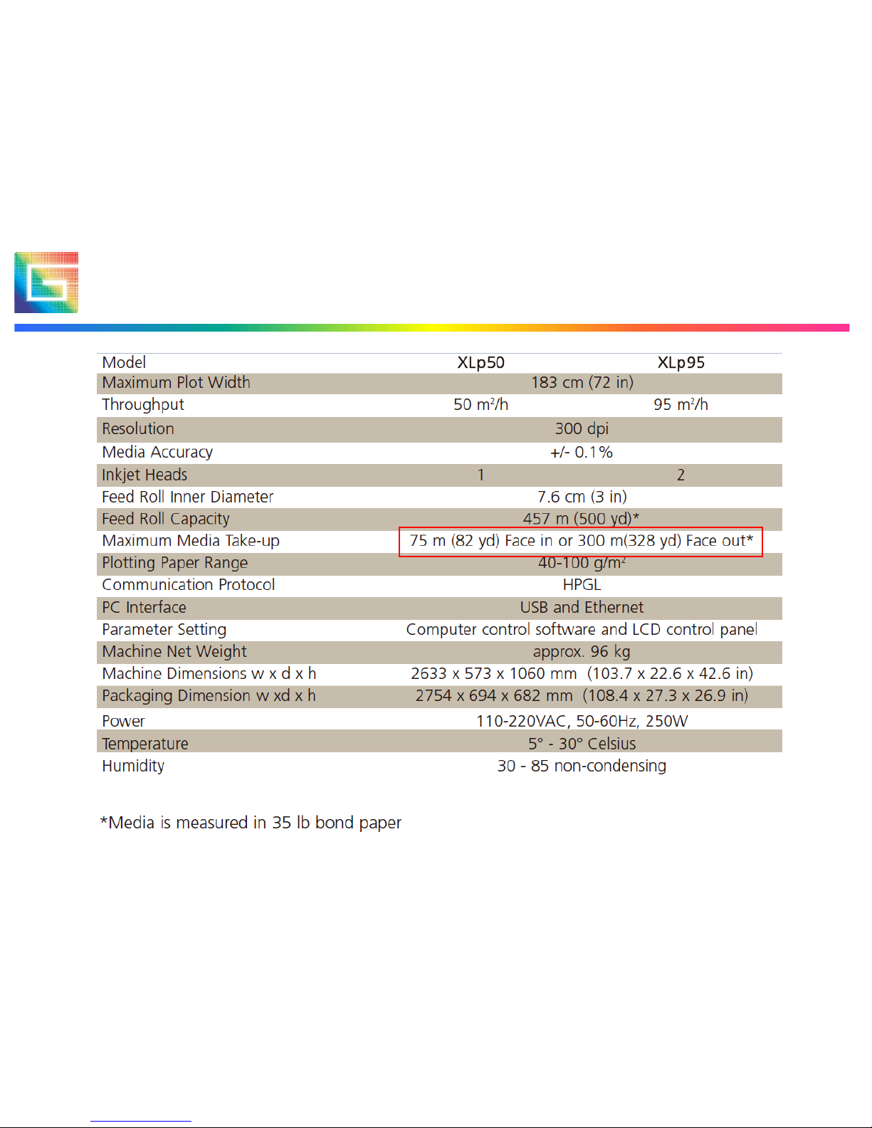
Overview: Technical Specifications
Page 6

6XLp Installation & Configuration, June 2010
Hardware Installation
• Unpack and assemble the plotter.
• Assembly is fairly simple and you should refer
to the XLp Getting Started Manual and the
XLp Installation Instructions available on
GERBERnet technical library.
• For a live demonstration you can view the
XLp Installation Video, also available on
GERBERnet.
Page 7

7XLp Installation & Configuration, June 2010
Hardware Installation (step by step)
1. Upon reception of the
system, please check the
crate for visible damage
and report back to your
local Gerber representative.
2. Remove the top and front
of the plotter crate.
Page 8
8XLp Installation & Configuration, June 2010
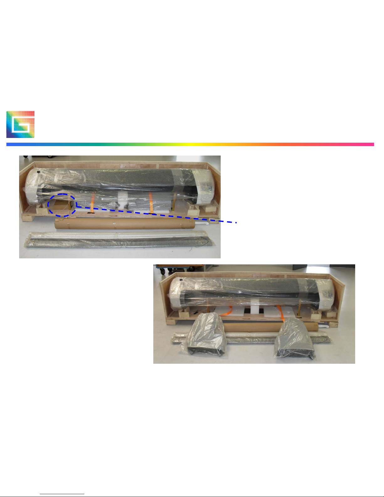
Hardware Installation (step by step)
3. Remove foam blocks,
paper roll, cross member
and paper bars from the
crate.
Also remove the cardboard
box that is glued on the
bottom of the crate
4. Remove the left and
right base assy from the
crate.
Page 9
9XLp Installation & Configuration, June 2010
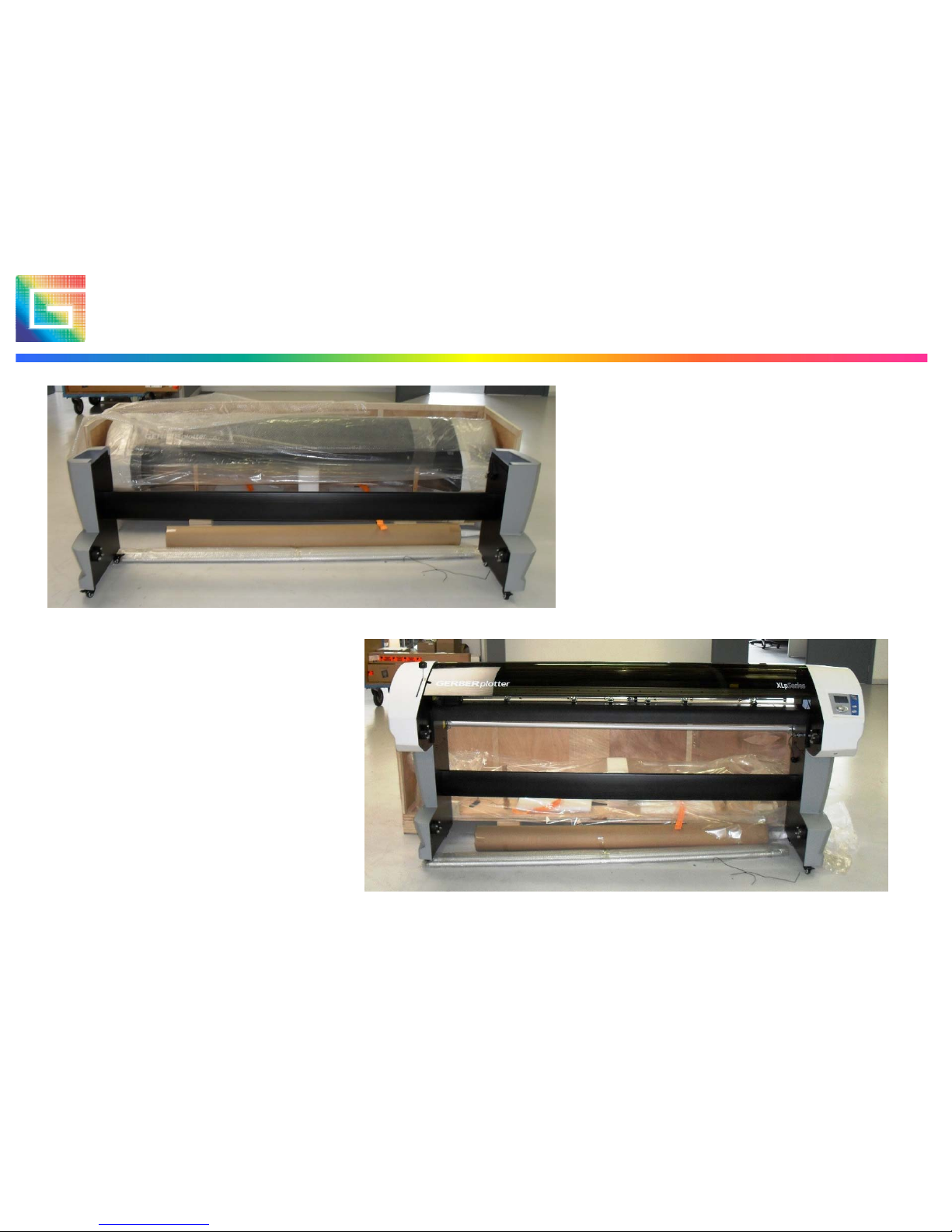
Hardware Installation (step by step)
5. Unpack and assemble
the plotter stand, using the
M6 screws and 5mm Allen
wrench supplied in the
cardboard box.
6. Remove all protective
plastic from the plotter top
and place it on the stand.
2 persons will be needed
for the lifting
Page 10
10XLp Installation & Configuration, June 2010
Hardware Installation (step by step)
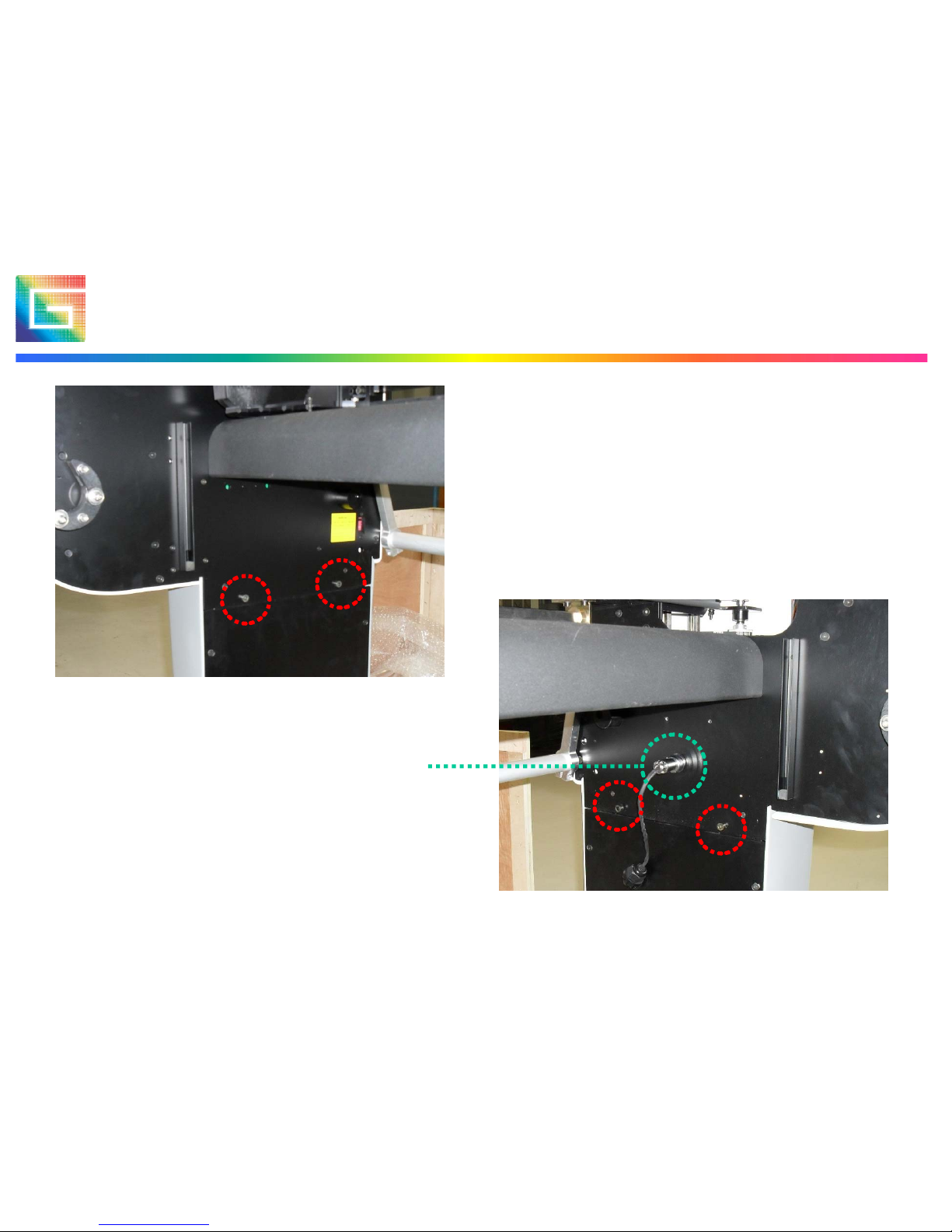
7. Secure the plotter top to the
base using the 4 remaining M6
screws and 5mm Allen wrench
supplied.
8. Do not forget to plug in the
connector for the paper supply
motor in the right base assembly
Page 11

11XLp Installation & Configuration, June 2010
Hardware Installation (step by step)
9. Make sure the voltage
selection switch on the left
base assembly is set for the
correct value (usually 220V)
10. Remove the screw that
blocks the carriage for
transport.
Page 12
12XLp Installation & Configuration, June 2010
Hardware Installation (step by step)
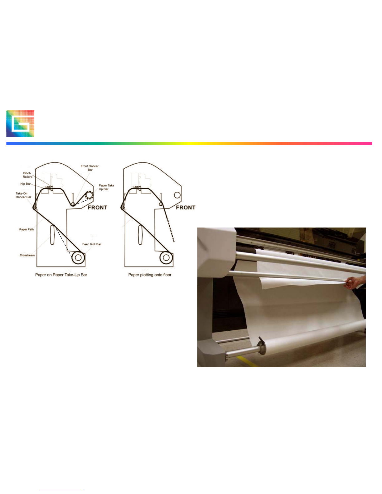
11. Feed the paper through the
system as shown on the drawing to
the left.
Paper can go either clock wise or
counter clock wise depending on
the roll.
Either take up or drop on floor
Page 13

13XLp Installation & Configuration, June 2010
Hardware Installation (step by step)
12. Open the little door at the
side of the plotter crate to find
your power cable
13. Plug the cable in the back of
the left base assembly and
power up. After initializing the
carriage and cleaning station the
screen should look like this.
Don’t forget to put the
cartridge(s) in or you will get an
error message.
Page 14

14XLp Installation & Configuration, June 2010
Software Installation
• The XLp Plotter operates in a similar way as an
Infinity Plotter. You can plot using either Winplot or
AccuMark 8.3.0. or higher. If the customer doesn’t
want to upgrade the AccuMark software then they will
have to supply a separate networked Windows PC to
run Winplot.
• Software installation is best done without the XLp
connected to the computer.
• Insert the WinPlot CD delivered with the system and
install Winplot first, then install the XLp update.
Page 15

15XLp Installation & Configuration, June 2010
Software installation
Install Winplot first
Then install the XLp Update
Page 16

16XLp Installation & Configuration, June 2010
Software installation
• Now insert the XLp CD to install the interface
program (V2.7.1 or higher)
• After the installation of the XLp interface you
can plug the USB connector in the plotter and
Windows will automatically install the required
drivers.
Page 17

17XLp Installation & Configuration, June 2010
Software installation
Page 18

18XLp Installation & Configuration, June 2010
Gerber Device Configuration
• On the Start menu, point to Control Panel.
• Double click the Gerber Device icon.
• The Gerber Device Configuration window will
appear.
• Click the Plotter tab (only on AccuMark systems).
• In the Type box, select XLP USB PLOTTER (XLP-
PLOTTER).
• In the Settings box COM-W will appear.
• Click Apply.
• Click OK.
Page 19

19XLp Installation & Configuration, June 2010
Gerber Device Configuration
Select this plotter
type
Page 20

20XLp Installation & Configuration, June 2010
XLp Interface
• Unlike the Infinity Interface. The XLp Interface
has two different windows to chose from (when
you right click on the plotter icon).
• System Setting:
Allows you to
perform all
adjustments and
calibrations to the
XLp.
• Plotter Status: Allows
for monitoring ink
and paper usage
Page 21

21XLp Installation & Configuration, June 2010
XLp Interface: Plotter Status
Percentage of ink
remaining in cartridge
(estimate)
Progress bar to indicate
how much of the current
job has been send to the
XLp
This window will allow you to monitor the ink levels
in the cartridges, check the status of the plotted job
(length and width) and monitor the remaining paper
and even show the temperature inside the plotter.
Page 22

22XLp Installation & Configuration, June 2010
Machine Setting: Plot Tab
Line thickness in dots, setting
depends on the type of paper
used.
After much testing we have
discovered for best print quality
/ ink usage change the Line
Width to 3 and select the
Economy Mode.
This value is the start of plot in
reference to system 0.
Value can be set manually.
Page 23

23XLp Installation & Configuration, June 2010
Machine Setting: Ink Tab
Ink contents can be
manually set (i.e. when
putting back used
cartridges after
overnight printing)
For every cartridge
there will be an input
box available
Page 24

24XLp Installation & Configuration, June 2010
Machine Setting: Paper Tab
Initial length of new paper
roll.
Change take up direction
(default is CW)
Perform paper edge
sensing at initialize
Change paper feed
direction (default is CW)
Page 25

25XLp Installation & Configuration, June 2010
Machine Setting: System Tab
Sets the units of measurement for the parameters
(except for calibration).
Detects and stops plotting
when cover is opened.
Performs extended
cartridge test at every
initialize
Prevents cartridge clean
during jobs
Page 26

26XLp Installation & Configuration, June 2010
Machine Setting: Communication
Used to select the means
of communication
between Winplot and the
XLP.
When selecting TCP/IP
an additional field to fill
out the IP address will
show.
Currently only USB
communication is
available on XLp.
Page 27

27XLp Installation & Configuration, June 2010
Machine Setting: Calibration tab
Used to perform the required
calibrations at first install and
at cartridge change.
XLp50 does not have
cartridge overlap & cartridge
separation alignments'
Each plotter leaves the
factory “Calibrated” and the
values stored in the firmware
will be uploaded to the XLp
I/F after communication
between the plotter and XLp
I/F has been done.
Page 28

28XLp Installation & Configuration, June 2010
Cartridge Alignment : XGap
1. Click the X Gap button to run the X Gap calibration.
NOTE: The plotter will begin printing.
2. Check the plot for the line and corresponding numeric value that
represents the best match of the two printed lines
3. Add or subtract this value from the displayed value in the XGap
box (i.e. if best match is 3 and current X Gap value is -9, the new
value will be -6)
4. Enter the new numeric value from step 3 in the XGap box.
5. Click Apply.
6. Repeat the Calibration if required until the zero value displays
the best match of the two drawn lines.
Page 29

29XLp Installation & Configuration, June 2010
Cartridge Alignment: Overlap
1. Click the Start Cartridge Overlap Alignment button to run the
Cartridge Overlap calibration.
NOTE: The plotter will begin printing.
2. Check the plot for the line and corresponding numeric value that
represents the best match of the two printed lines.
3. Enter the numeric value from step 2 in the Cartridge box.
4. Click Apply.
5. Repeat the calibration if required.
NOTE: This alignment is not present on XLp50
Page 30

30XLp Installation & Configuration, June 2010
Cartridge Alignment: Separation
1. Click the Start Cartridge Separation Alignment button to run
the Y Head calibration.
NOTE: The plotter will begin printing.
2. Check the plot for the line and corresponding numeric value that
represents the best match of the two printed lines.
3. Add or subtract the numeric value from step 2 from the current
value.
4. Enter the numeric value from step 3 in the Y Head Calibration
box.
5. Click Apply.
6. Repeat the calibration if required.
NOTE: The default value is 261 (2.61 cm or 26.1 mm) on XLp95
Page 31

31XLp Installation & Configuration, June 2010
Cartridge Alignment: Forward Reverse
1. Click the YGap button to run the Y Gap calibration.
NOTE: The plotter will begin printing.
2. Check the plot for the line and corresponding numeric value that
represents the best match of the two printed lines.
3. Add or subtract the value from step 2 from the actual value.
4. Enter the numeric value from step 3 in the Y Gap box.
5. Click Apply.
6. Repeat the calibration if required.
Page 32

32XLp Installation & Configuration, June 2010
Calibration : Box Test
Box Test is used to calibrate the
step size of the plotter. It will
print a 1m square, which you
then measure and input the
exact size (in actual length
fields).
After input of the values you
click Confirm and then Apply.
Exit the XLp interface before you
do the test again (Actual Length
values will be reset to 1 then).
Note: X-axis step size calibration
needs to be checked if customer
changes paper type
Page 33

33XLp Installation & Configuration, June 2010
Service Level
To enter the service level of the XLp interface
program you are required to enter a password.
The password is unique to every system as it is
the serial number +1 for every digit.
In this case: serial number 2042100809
password 315321191:
(9 becomes : not 0)
After you click on ‘confirm’ additional
parameters will become visible.
Page 34

34XLp Installation & Configuration, June 2010
Service Level : Plot Tab
To get additional spacing
between jobs.
Set the plotting speed to
a lower value.
Make sure no one changes
the values of X and Y
scaling. They have to be
set at 1 and NOTHING
ELSE.
Allows to switch to unidirectional printing (slower
but better quality)
Page 35

35XLp Installation & Configuration, June 2010
Service Level : Ink Tab
Can be set to 1 if required
(note that the system will
then react as an XLp50)
Will give a message
when ink in cartridge
becomes low
Page 36

36XLp Installation & Configuration, June 2010
Service Level : Paper Tab
Signals when paper take
up motor is running too
long (paper slipping).
Signals when paper feed
motor is running too long
(paper slipping).
Uncheck for drop on floor
(can also be set on plotter
itself, but will reset after
job).
Leave like this.
Signals when system is out
of paper.
Page 37

37XLp Installation & Configuration, June 2010
Service Level : System Tab
Do not touch these
values (result unknown)
Resolution should
always be on 300DPI
Page 38

38XLp Installation & Configuration, June 2010
Service Level : Updating Firmware
• Latest firmware will be made available via
GERBERnet.
• When you click Update Firmware a standard
browsing window will pop up instructing you to
select the firmware file to upload (the XLp uses
*.hex files).
• Once selected the system will ask you to confirm
twice before it uploads the firmware to the plotter
(takes only a few seconds).
• After firmware update the plotter will restart
automatically.
Page 39

39XLp Installation & Configuration, June 2010
Maintenance
• To keep a smooth Y-axis movement it is
recommended to clean and slightly oil both
round ways at regular intervals (2-3 weeks
depending on usage). Make sure you do not
touch the Code Strip with oil (use a small
piece of oiled rag to sweep the round ways).
• Make sure the Y Encoder Strip is free of dust
and debris. If not then the head may take-off
at a high speed and slam into the Cleaning
Station.
Page 40

40XLp Installation & Configuration, June 2010
Maintenance
• Over time ink will build up in the cleaning
station due to the cleaning cycles where the
system purges the jets. This can cause print
quality issues if the ink builds up near the jets.
If this occurs, it is recommended to (remove
and) clean the capping rubbers using warm
water and soap.
Page 41

41XLp Installation & Configuration, June 2010
Components: left side
Page 42

42XLp Installation & Configuration, June 2010
Components: Operator Side
Page 43

43XLp Installation & Configuration, June 2010
Questions ?
 Loading...