

Page 1

Copyright Notice
COPYRIGHT © 2007 Gerber Scientific International. All Rights Reserved.
Portions Copyright © 2001 artofcode LLC. This software is based in part on the work of the Independent
JPEG Group. Portions Copyright © 1998 Soft Horizons. All Rights Reserved.
Ghostscript Included.
This document may not be reproduced by any means, in whole or in part, without written permission of
the copyright owner.
This document is furnished to support OMEGA. In consideration of the furnishing of the information
contained in this document, the party to whom it is given assumes its custody and control and agrees to
the following:
1 The information herein contained is given in confidence, and any part thereof shall not be copied or
reproduced without written consent of Gerber Scientific International.
2 This document or the contents herein under no circumstances shall be used in the manufacture or
reproduction of the article shown and the delivery of this document shall not constitute any right or
license to do so.
Printed in USA
GSP, EDGE, and GRAPHIX ADVANTAGE are registered trademarks, and OMEGA, GERBER MAXX,
GERBER EDGE FX, EDGE Match, GerberColor, GerberColor Spectratone, GERBER SOLARA, GERBER
P2C, ImageRIP, Vantage Scan, SUPER CMYK, Gerber ColorID, MacImprint, Matched Technology
System, and ART Path are trademarks of Gerber Scientific Products. Adobe Illustrator and Encapsulated
PostScript are registered trademarks of Adobe Systems, Inc. Artifex, the Artifex logo, Ghostscript, and
the Ghostscript logo are registered trademarks of Artifex Software, Inc. CorelDRAW is a registered
trademark of Corel Systems Corporation. 3M and Scotchcal are registered trademarks of 3M. HewlettPackard is a registered trademark and HPGL is a trademark of Hewlett-Packard Company.
MonacoEZcolor and MonacoSENSOR are trademarks of X-Rite, Inc. TrueType is registered trademark of
Apple Computer, Inc. registered in the USA and other countries. Microsoft and Windows, are registered
trademarks of Microsoft Corporation in the United States and other countries.
PANTONE® Colors displayed may not match PANTONE-identified standards. Consult current
PANTONE Color Publications for accurate color. PANTONE® and other Pantone, Inc. trademarks are
the property of Pantone, Inc. © Pantone, Inc., 2005.
Pantone, Inc. is the copyright owner of color data and/or software which are licensed to Gerber Scientific
Products. to distribute for use only in combination with Gerber OMEGA 2.5. PANTONE Color Data
and/or Software shall not be copied onto another disk or into memory unless as part of the execution of
Gerber OMEGA 2.5.
Page 2

Variables
There are many variables in process reproduction of colors generated by the GERBER EDGE and
GERBER MAXX, any one of which may affect the quality of the Gerber simulations of PANTONE Colors,
including:
• Type of media/paper used
• Type of ink film used
• Effective final resolution
• Dot structures/halftones
For optimal results we recommend that the following materials be used:
1. 3M Scotchcal 220-10 or 225-10 Gloss White Vinyl
2. GerberColor SUPER CMYK Foils
THE PANTONE-IDENTIFIED COLOR DISPLAYED ON THE PRINT AND/OR COPY GENERATED BY
THIS SOFTWARE HAVE NOT BEEN EVALUATED NOR ARE THEY APPROVED BY PANTONE, INC.
TO BE IN COMPLIANCE WITH PANTONE, INC.'S COLOR VALUES OR STANDARDS. Consult
current PANTONE Color publications for accurate colors.
Page 3

Book One: Welcome ................................................................................................................................1
Chapter 1: Introducing the OMEGA Programs...................................................................................3
Running in Demo Mode .......................................................................................................................................4
Chapter 2: Where to Get Help ...............................................................................................................7
About the manuals ................................................................................................................................................7
Warnings, cautions, notes, and tips.....................................................................................................................7
Keystroke and menu choice formats...................................................................................................................8
Accelerator keys.....................................................................................................................................................8
Context menus .......................................................................................................................................................8
Mouse terminology................................................................................................................................................9
Getting help right in OMEGA.............................................................................................................................. 9
Other Information on the OMEGA CD.............................................................................................................11
Specific technical support...................................................................................................................................12
Contacting Gerber Technical Support...............................................................................................................12
Gerber web site ....................................................................................................................................................12
Chapter 3: Opening and Closing Files................................................................................................13
Creating a new file...............................................................................................................................................13
Opening an existing file ......................................................................................................................................13
Adding a file to an open PLT file (Importing).................................................................................................15
Adding multiple files to an open PLT file (importing)...................................................................................17
Placing multiple copies of a file in an open PLT file.......................................................................................18
Opening Gerber Clip Art (GCA) files ...............................................................................................................19
Closing files ..........................................................................................................................................................21
Chapter 4: Saving Files and Viewing Properties..............................................................................23
Saving PLT files....................................................................................................................................................23
AutoBackup feature.............................................................................................................................................24
Saving a file for the MAXX 2..............................................................................................................................24
Saving a copy of a PLT file .................................................................................................................................24
Saving plot files in an older OMEGA format...................................................................................................24
Saving files in formats other than PLT..............................................................................................................25
Viewing Document Properties...........................................................................................................................26
Tracking elapsed design time.............................................................................................................................27
Book Two: Understanding Composer Tools .....................................................................................29
Chapter 5: Setting Up Composer's Work Surface............................................................................31
Composer work surface......................................................................................................................................31
Window controls..................................................................................................................................................33
Sizing the work surface to the design ...............................................................................................................33
Using the Natural Layout option.......................................................................................................................35
Viewing the design..............................................................................................................................................36
Zooming in or out on the design .......................................................................................................................38
Setting Preferences using Tools > Options.......................................................................................................39
Chapter 6: Using Layers.........................................................................................................................55
Rules for designing with layers .........................................................................................................................56
Using the Layer Manager ...................................................................................................................................58
Using the Layer Menu.........................................................................................................................................66
Page 4

Print Order and Layers Overview.....................................................................................................................69
Understanding Print Order in Composer ........................................................................................................70
Outputting by layers to GSPPlot .......................................................................................................................72
Importing layers...................................................................................................................................................72
Chapter 7: Selecting the Elements of the Design ...........................................................................77
Selecting elements of the design........................................................................................................................77
Book Three: Creating the Basic Design Text and Shapes..............................................................83
Chapter 8: All About Text......................................................................................................................85
Entering text .........................................................................................................................................................85
Editing text..........................................................................................................................................................103
Using Change Case to alter the case of text....................................................................................................104
Spacing characters, lines and columns............................................................................................................104
Resetting the line spacing .................................................................................................................................107
Setting line length and column height............................................................................................................107
Arranging the text in the design......................................................................................................................109
Converting text to shapes .................................................................................................................................110
Working with Spell Check................................................................................................................................111
Chapter 9: Creating Shapes............................................................................................................... 119
Techniques for drawing on the work surface................................................................................................119
Rectangles and squares.....................................................................................................................................119
Circles and ellipses ............................................................................................................................................120
Decorative borders.............................................................................................................................................120
Creating a surround shape ...............................................................................................................................122
Multi-sided shapes (stars and polygons)........................................................................................................124
Adding GerberCUT Targets.............................................................................................................................127
Freehand drawing..............................................................................................................................................129
Chapter 10: Sizing, Slanting, Flipping, and Rotating ................................................................... 133
Sizing ...................................................................................................................................................................133
Slanting................................................................................................................................................................135
Flipping or mirroring ........................................................................................................................................136
Rotating...............................................................................................................................................................137
Chapter 11: Grouping, Moving, Justifying, and Spacing............................................................. 141
Grouping and ungrouping...............................................................................................................................141
Locking or Unlocking Objects.......................................................................................................................... 142
Moving objects on the work surface................................................................................................................143
Justifying.............................................................................................................................................................144
Adding and removing guidelines ................................................................................................................... 145
Spacing ................................................................................................................................................................146
Chapter 12: Measuring and Dimensioning....................................................................................149
Measuring distance and angles........................................................................................................................149
Measuring the distance around objects ..........................................................................................................152
Determining the area of objects .......................................................................................................................152
Dimensioning Summary...................................................................................................................................153
Understanding Dimensioning..........................................................................................................................156
Dimensioning .....................................................................................................................................................157
The Dimensions Toolbar...................................................................................................................................158
Page 5

Dimensioning Properties Toolbar ...................................................................................................................162
Book Four: Adding Color to the Design.......................................................................................... 167
Chapter 13: Current Style Affects the Color in the Design ........................................................169
Defining the current style .................................................................................................................................169
Setting the current style ....................................................................................................................................170
Setting the current style to none ......................................................................................................................170
Changing the current style using the Extract Style command ....................................................................170
Making a new current style without selecting an object ..............................................................................171
Assigning the current style...............................................................................................................................172
Creating filled text or objects without cutlines..............................................................................................172
Chapter 14: Making, Using, and Editing Palettes.........................................................................175
Displaying palettes on the Composer work surface.....................................................................................175
Making a job palette using Gerber vinyl ........................................................................................................177
Using Palette Manager......................................................................................................................................179
Using Gerber palettes in Adobe Illustrator and CorelDRAW..................................................................... 182
Chapter 15: Understanding Vinyl Colors ........................................................................................ 187
Displaying a vinyl palette................................................................................................................................. 187
Assigning vinyl colors to objects .....................................................................................................................187
Selecting objects of the same vinyl color ........................................................................................................189
Chapter 16: Changing Vinyl Colors to Spot Foil Colors............................................................... 191
Posterizing methods..........................................................................................................................................191
Understanding the Posterize Selected Shapes dialog box............................................................................192
Posterizing a job.................................................................................................................................................195
Troubleshooting.................................................................................................................................................196
Chapter 17: Filling Objects with Colors for Printing.................................................................... 197
Where does the color come from? ...................................................................................................................197
Assigning attributes for printing.....................................................................................................................197
Filling with a clear fill........................................................................................................................................199
Filling with a spot foil .......................................................................................................................................199
Filling with a process foil..................................................................................................................................202
Filling with a gradient fill.................................................................................................................................204
Filling with Spectratone colors.........................................................................................................................207
Editing fill attributes..........................................................................................................................................209
Naming custom process colors ........................................................................................................................211
Changing from a spot fill to a process fill.......................................................................................................211
Automatically convert Process fills to Spot fills ............................................................................................212
Chapter 18: Choosing and Assigning Halftones........................................................................... 213
What is a halftone?.............................................................................................................................................213
Choosing the best halftone for the fill.............................................................................................................213
Non-Optimized Halftones Detected ...............................................................................................................216
Printing with Non-optimized Halftones when Auto-Substitution is On...................................................217
Assigning a halftone..........................................................................................................................................217
Editing halftones................................................................................................................................................218
Substituting halftones........................................................................................................................................218
Page 6

Chapter 19: Choosing a Fill Color that Matches Printer Output............................................... 221
Printing EDGE Match Color Matching System charts..................................................................................221
Choosing and assigning an EDGE Match color.............................................................................................222
Chapter 20: Making and Using GerberColor Spectratone Colors.............................................225
Making a Spectratone chart of all possible colors in inventory................................................................... 225
Making a Spectratone chart of some colors in inventory.............................................................................226
Printing a chart of Spectratone tints................................................................................................................228
Filling objects with Spectratone colors............................................................................................................229
Chapter 21: Assigning PANTONE Colors ........................................................................................231
Using ColorID to choose software simulations of solid PANTONE Colors..............................................232
Chapter 22: Strokes ⎯ Adding Print Thickness to the Outline of Objects ............................ 233
What is a stroke? ................................................................................................................................................233
Adding strokes to an object..............................................................................................................................233
Editing stroke attributes....................................................................................................................................236
Global stroke width editing..............................................................................................................................237
Converting strokes to shapes with Expand Strokes......................................................................................238
Book Five: Making the Design Print and Cut Correctly............................................................... 241
Chapter 23: Before Printing or Cutting, Check the Design ........................................................ 243
Using the Select and View menus to check a job...........................................................................................243
Checking and selecting vinyl colors................................................................................................................244
Checking and selecting fills and strokes by color .........................................................................................244
Checking and selecting fills and strokes by color type.................................................................................245
Checking and selecting fills and strokes by halftone type...........................................................................245
Checking and selecting which objects will cut, print, or both.....................................................................246
Checking and selecting images and image templates ..................................................................................247
Checking and selecting overlaps, overprints, or primer..............................................................................247
Checking and selecting Small Text by color type..........................................................................................247
Checking and selecting open shapes...............................................................................................................247
Checking and selecting Locked Objects..........................................................................................................247
Checking and selecting Clipping Paths..........................................................................................................248
Checking and selecting dimensions................................................................................................................248
Selecting stacked objects on the work surface ...............................................................................................248
Chapter 24: Five Steps to Successful Output................................................................................ 249
Overview: 5 steps to successful thermal printer output...............................................................................249
1. Check and assign the vinyl color.................................................................................................................249
2. Check and assign fills and strokes...............................................................................................................250
3. Check and assign or remove object cut lines..............................................................................................250
4. Check and rearrange objects in the stacking order ...................................................................................250
5. Combining and filling groups for printing ................................................................................................251
Chapter 25: Solving Printing and Registration Problems...........................................................253
Check the job ......................................................................................................................................................253
Poor print-to-cut registration ...........................................................................................................................253
Poor print-to-print registration........................................................................................................................254
Changing the vinyl and foil print order .........................................................................................................262
Printing a light color over a darker color........................................................................................................264
Page 7

Changing the darkness of prints......................................................................................................................264
Correcting colors for images ............................................................................................................................265
Book Six: Color Management and Importing/Exporting Files ..................................................267
Chapter 26: Practical Hands-On Color Management .................................................................. 269
Step 1: Setting up Color Management ............................................................................................................269
Step 2: Setting up Image Thumbnail...............................................................................................................271
Step 3: Assigning the vinyl family...................................................................................................................272
Chapter 27: Importing Files into Composer .................................................................................. 273
Understanding the Import dialog box ............................................................................................................273
Choosing the best import filter ........................................................................................................................276
Understanding graphic file formats................................................................................................................277
The role of Color Management when importing files ..................................................................................279
Importing common file types...........................................................................................................................280
Importing Raster file filters - TIF, BMP, JPG, GIF .........................................................................................280
Importing Adobe format files (AI 7.0 or higher, PDF, EPS, or PS) .............................................................282
Importing AI 1.1 thru 8.0 and CMX 5.0/6.0 files for vinyl printing ...........................................................289
Importing AI 1.1 thru 8.0 and CMX 5.0/6.0 files for vinyl cutting .............................................................290
Importing AI 8.0 or earlier, CMX (5.0/6.0), or EPS files...............................................................................292
Defining a Cut Contour in other software......................................................................................................299
Importing CorelDRAW clipart ........................................................................................................................300
Importing CorelDRAW Drawing Format (CDR) files..................................................................................301
Using the Clipboard to import data into Composer.....................................................................................301
Importing other file types.................................................................................................................................302
Importing Gerber Clip Art (GCA) file ............................................................................................................302
Importing DXF files using the (GSP) AutoCAD Drawing Interchange Filter ...........................................303
Importing AutoCAD Drawing Format (DWG) files.....................................................................................304
Importing Adobe Acrobat Portable Document Format (PDF) ....................................................................304
Importing Microsoft Windows Metafile (WMF) ...........................................................................................305
Chapter 28: Exporting Files from Composer................................................................................ 307
Exporting all or portions of a file.....................................................................................................................307
Exporting to a Hot Folder.................................................................................................................................310
Exporting common file types ...........................................................................................................................311
Exporting to BMP, GIF, JPG, or TIF file formats ...........................................................................................311
Exporting to Adobe Illustrator – AI or EPS format using the GSP filter....................................................312
Using the Clipboard to Export Data from Composer................................................................................... 317
Exporting to an Encapsulated PostScript File (EPS) or Adobe Illustrator File (AI)..................................317
Exporting to an AutoCAD Drawing Web Format (DWF)............................................................................319
Exporting to a DXF (GSP) AutoCAD Drawing Interchange File................................................................320
Exporting to AutoCAD Drawing Interchange File (DXF)............................................................................321
Exporting to a Gerber Artwork Definition File (GAD).................................................................................322
Exporting to Hewlett-Packard Graphics Language (HGL)..........................................................................322
Exporting to IGES Drawing File Format (IGES)............................................................................................323
Exporting to a Z-soft PC Paintbrush Bitmap (PCX)......................................................................................324
Exporting to Adobe Acrobat File Format (PDF)............................................................................................326
Exporting to PhotoShop File Format (PSD)....................................................................................................328
Exporting to Microsoft Windows Metafile (WMF).......................................................................................329
Exporting to WordPerfect Graphic File Format (WPG) ...............................................................................331
Page 8

Chapter 29: Using File Converter .................................................................................................... 333
Choosing File Converter options.....................................................................................................................333
Importing multiple files (batch conversion)...................................................................................................334
Exporting multiple files (batch conversion)...................................................................................................334
File conversion troubleshooting ......................................................................................................................335
Chapter 30: Remapping Colors for Imported CMX Files ............................................................337
Understanding color models............................................................................................................................337
Book Seven: Adding Artwork and Other Files to the Design ....................................................343
Chapter 31: Working with Images ...................................................................................................345
Adding images to the design ...........................................................................................................................345
Saving an embedded image .............................................................................................................................350
Changing from a linked to an embedded image...........................................................................................350
Importing paths from an image.......................................................................................................................351
Viewing images in the design..........................................................................................................................352
Editing images in Composer............................................................................................................................355
Updating an image file in OMEGA................................................................................................................. 357
Filling images .....................................................................................................................................................358
Chapter 32: Converting Images to Cut Shapes ............................................................................. 361
Converting a color image to a cut shape ........................................................................................................361
Converting a black and white image to a cut shape .....................................................................................364
Chapter 33: Adding Cutlines to Artwork ........................................................................................ 367
Using Generate Decal Cut ................................................................................................................................367
Chapter 34: Using Clipping Paths .................................................................................................... 373
Understanding Clipping Paths ........................................................................................................................373
Chapter 35: Scanning Artwork.......................................................................................................... 379
Storing and outputting scanned images.........................................................................................................379
Methods of getting scanned data into Composer..........................................................................................383
Methods of vectorizing raster data..................................................................................................................385
Color Management and scanning....................................................................................................................386
Chapter 36: Digitizing Artwork ......................................................................................................... 387
Installing the tablet ............................................................................................................................................387
Understanding the digitizing process: an overview.....................................................................................388
Preparing artwork for digitizing .....................................................................................................................389
Using the digitizing puck .................................................................................................................................390
Using the tablet .................................................................................................................................................. 391
Digitizing the artwork....................................................................................................................................... 391
Digitizing: examples and tips...........................................................................................................................391
Digitizing shapes ...............................................................................................................................................393
Editing the digitized design .............................................................................................................................394
Digitizing exercises............................................................................................................................................395
Book Eight: Editing the Design and Shapes .................................................................................. 403
Page 9

Chapter 37: Using the Edit Menu.....................................................................................................405
Using Undo and Redo....................................................................................................................................... 405
Copying parts or all of a design.......................................................................................................................405
Using Duplicate to copy and offset an object.................................................................................................407
Deleting parts of the design..............................................................................................................................407
Chapter 38: Detail Editing Segments and Points of Vector Objects........................................ 409
Selecting objects or parts of objects for editing..............................................................................................409
Copying and pasting segments........................................................................................................................411
Changing curves to lines and lines to curves.................................................................................................411
Aligning points...................................................................................................................................................412
Adding points to objects ...................................................................................................................................413
Deleting points from an object.........................................................................................................................415
Using the Move Tool (hook).............................................................................................................................416
Moving points ....................................................................................................................................................417
Moving segments............................................................................................................................................... 419
Bending line segments ......................................................................................................................................421
Changing the flex of curves..............................................................................................................................422
Closing open points with the Move tool ........................................................................................................422
Automatically joining open shapes.................................................................................................................423
Dividing an object into multiple objects.........................................................................................................424
Making the corners of an object rounded using the Round Corner tool....................................................425
Sharpening the corners of an object using the Sharp Corner Tool..............................................................426
Changing the corners of an object with Fillet Corner...................................................................................426
Smoothing objects with the Smooth Path tool ...............................................................................................428
Freehand Drawing.............................................................................................................................................429
Designate the first point of a shape.................................................................................................................429
Chapter 39: Reducing the Number of Points with the Thin Command .................................. 431
Removing points................................................................................................................................................431
Smoothing jagged edges ...................................................................................................................................432
Controlling the number of points thinned .....................................................................................................433
Minimizing the error between remaining points after thinning.................................................................435
Book Nine: Adding Flair to the Design ........................................................................................... 437
Chapter 40: Outlining Objects ..........................................................................................................439
Creating outlines................................................................................................................................................ 439
Hiding, encasing, and contouring objects ......................................................................................................441
Changing the spacing between multiple outlines.........................................................................................443
Adding and deleting outlines ..........................................................................................................................446
Editing outline settings for sharp corners ......................................................................................................447
Saving the outline for later use ........................................................................................................................447
Chapter 41: Adding Shadows ...........................................................................................................449
Creating a shade or drop shadow ...................................................................................................................450
Creating a cast shadow .....................................................................................................................................451
Choosing the shadow output options............................................................................................................. 451
Creating different types of jobs using Shadow..............................................................................................454
Editing or deleting Shadows............................................................................................................................457
Viewing the Design ........................................................................................................................................... 457
Exercises..............................................................................................................................................................457
Page 10

Chapter 42: Distorting and Warping Objects ................................................................................ 463
Distorting an object............................................................................................................................................463
Warping an object..............................................................................................................................................464
Chapter 43: Fitting Text to a Path.................................................................................................... 469
Working with the Fit Text to Path dialog box................................................................................................469
Selecting, reverse selecting, and deselecting text ..........................................................................................470
Positioning text along the path ........................................................................................................................471
Changing the spacing of text............................................................................................................................473
Changing the height of text ..............................................................................................................................474
Reversing the path.............................................................................................................................................475
Hiding the path..................................................................................................................................................475
Changing the angle of the text .........................................................................................................................476
Slanting the text..................................................................................................................................................477
Fitting shapes to a path .....................................................................................................................................478
Using text as a path............................................................................................................................................478
Magnifying text using tools..............................................................................................................................479
Chapter 44: Creating Special Effects............................................................................................... 481
Using the Effects dialog box.............................................................................................................................481
Using Special ......................................................................................................................................................483
Using Stripes.......................................................................................................................................................485
Using Layers....................................................................................................................................................... 488
Using Overlap ....................................................................................................................................................492
Using Contour....................................................................................................................................................494
Using Effects Library......................................................................................................................................... 494
Book Ten: Repeating Text and Objects ..........................................................................................499
Chapter 45: Repeating Objects ⎯ Text or Shapes....................................................................... 501
Repeating in a line, matrix, or diagonal pattern............................................................................................501
Changing the spacing, size, and alignment for repeats................................................................................502
Chapter 46: Merging Text and Numbers ........................................................................................ 507
Repeating and merging text .............................................................................................................................507
Repeating text with AutoNumbers .................................................................................................................511
Merging text with AutoNumber......................................................................................................................514
Book Eleven: Managing, Converting, and Designing Fonts ....................................................... 515
Chapter 47: Managing Fonts............................................................................................................. 517
Exploring the Font Manager program............................................................................................................517
Viewing Gerber Fonts in Font Manager .........................................................................................................520
Renaming a Gerber font style...........................................................................................................................522
Chapter 48: Viewing and Printing Installed Fonts ....................................................................... 527
Opening Font View............................................................................................................................................527
Viewing the list of installed fonts....................................................................................................................527
Printing the installed fonts ...............................................................................................................................531
Locating and copying characters in Font View .............................................................................................535
Chapter 49: Converting TrueType Fonts to OMEGA-Compatible Fonts .................................. 539
Using Font Converter........................................................................................................................................539
Page 11

Fine-tuning the font...........................................................................................................................................543
Tips for working with TrueType fonts ...........................................................................................................548
Backing up fonts.................................................................................................................................................549
Chapter 50: Designing and Building Your Own Fonts ................................................................551
Introduction to font designing.........................................................................................................................551
Inputting the artwork........................................................................................................................................552
Building the font ................................................................................................................................................572
Accessing the font..............................................................................................................................................579
Creating Fonts: Exercises..................................................................................................................................580
Book Twelve: Outputting the Job from Composer....................................................................... 591
Chapter 51: Sending the Job to a Plotter or Printer .................................................................... 593
Thermal printing and cutting the job..............................................................................................................593
Sending the job to an inkjet printer using Gerber ImageRIP.......................................................................595
Paper printing ....................................................................................................................................................595
Chapter 52: Sending the Job to a Person by E-Mail.................................................................... 599
Book Thirteen: Printing and Cutting the Job................................................................................. 601
Chapter 53: Opening and Closing GSPPlot.................................................................................... 603
Opening GSPPlot from Composer ..................................................................................................................603
Opening a GSPPlot from Windows.................................................................................................................606
Closing Windows...............................................................................................................................................606
Exiting GSPPlot..................................................................................................................................................606
Program Information.........................................................................................................................................607
Using the GSPPlot toolbar................................................................................................................................607
Viewing the GSPPlot toolbar............................................................................................................................607
Chapter 54: Setting Up the GSPPlot Window................................................................................ 609
Displaying the summary and status bars.......................................................................................................609
Displaying the rulers.........................................................................................................................................609
Modifying ruler properties...............................................................................................................................610
Managing windows........................................................................................................................................... 612
Sizing the work surface.....................................................................................................................................613
Zooming in on the job .......................................................................................................................................613
Viewing the attributes of a job .........................................................................................................................613
Using the GSPPlot Options dialog box...........................................................................................................615
Chapter 55: Managing Files in GSPPlot.......................................................................................... 617
File types created in GSPPlot ...........................................................................................................................617
Opening existing job files .................................................................................................................................618
Closing job files..................................................................................................................................................618
Understanding Layers and Print Order in GSPPlot......................................................................................619
Saving all preferences........................................................................................................................................622
Saving files for future use.................................................................................................................................622
Viewing a spool file...........................................................................................................................................626
Including special job instructions....................................................................................................................629
Chapter 56: Creating a Mirror Image and Reversing Print Order............................................631
Creating a mirror image....................................................................................................................................631
Printing a job on transparent material............................................................................................................631
Page 12

Printing a job on heat transfer paper...............................................................................................................632
Chapter 57: Multiple Copies in GSPPlot .......................................................................................633
Creating multiples of a job without panels....................................................................................................633
Setting the distance between repeats ..............................................................................................................634
Creating multiples of a job with panels..........................................................................................................635
Viewing a job with repeats and copies ...........................................................................................................635
Chapter 58: Advanced Setup Options............................................................................................. 637
Changing the size of a job.................................................................................................................................637
Choosing specific layers, vinyls, or foils to be output ..................................................................................639
Altering Print Settings.......................................................................................................................................646
Changing the weed border...............................................................................................................................648
Substituting halftones........................................................................................................................................649
Automatically optimizing halftones for MAXX 2 .........................................................................................650
Printing with non-optimized halftones when Auto-Substitution is turned on........................................651
Optimizing the print registration of black......................................................................................................652
Chapter 59: Working with Oversized Jobs..................................................................................... 653
Creating panels ..................................................................................................................................................653
Modifying panel size......................................................................................................................................... 654
Viewing panel size.............................................................................................................................................655
Selecting panels to output.................................................................................................................................655
Flipping panels...................................................................................................................................................658
Outputting each panel as a separate job.........................................................................................................658
Viewing panels...................................................................................................................................................659
Producing a job without gaps between panels..............................................................................................659
Ensuring print to cut registration with paneled jobs....................................................................................660
Chapter 60: Conserving Vinyl and Foil........................................................................................... 661
Rotating the job 90
°
to conserve vinyl..............................................................................................................661
Saving vinyl by positioning the job when plotting.......................................................................................661
Changing the start and end position of a job.................................................................................................662
Saving vinyl by positioning the job when printing.......................................................................................664
Minimizing vinyl usage with Reduce Frame.................................................................................................665
Minimizing foil usage .......................................................................................................................................666
Displaying vinyl and foil information ............................................................................................................667
Displaying the foil settings...............................................................................................................................667
Chapter 61: Choosing the Plotter or Printer.................................................................................. 669
Installing a plotter or printer............................................................................................................................669
Choosing a plotter and printer.........................................................................................................................669
Choosing a print mode......................................................................................................................................671
Resolving an EDGE 2 or EDGE FX Print Mode conflict ...............................................................................672
Selecting the material size.................................................................................................................................672
Changing plotter settings..................................................................................................................................673
Chapter 62: Cutting, Plotting, and Pouncing a Job ..................................................................... 681
Determining if there is sufficient vinyl for a job............................................................................................681
Minimizing tool travel during plotting ..........................................................................................................682
Cutting a job with multiple vinyls...................................................................................................................682
Plotting existing spool files...............................................................................................................................683
Page 13

Double-cutting a job ..........................................................................................................................................684
Sending the job to a plotter...............................................................................................................................684
Chapter 63: Printing a Job on a Vinyl Printer............................................................................... 687
Sending the job to a vinyl printer ....................................................................................................................687
Output Job Settings............................................................................................................................................687
Printing existing spool files ..............................................................................................................................688
Printing Process Colors.....................................................................................................................................689
Using the GerberColor Backing and Finish dialog box................................................................................689
Applying Multi-Spot Gradient Boost..............................................................................................................695
Printing a light color over a darker color........................................................................................................695
Viewing and changing the heat setting of a foil ............................................................................................696
Double-Hit White foil on the MAXX...............................................................................................................697
Viewing and printing dimensions................................................................................................................... 697
Chapter 64: Ensuring Print-to-Cut Registration........................................................................... 699
Calibrating the plotter to a printer ..................................................................................................................699
Configuring targets for accurate print-to-cut registration ...........................................................................703
Centering a job on the vinyl .............................................................................................................................710
Chapter 65: Gerber Queue Manager............................................................................................... 711
Installing output devices...................................................................................................................................712
Opening files for printing and cutting............................................................................................................712
Pausing and restarting a job.............................................................................................................................713
Displaying plotting information......................................................................................................................713
Removing jobs from Gerber Queue Manager................................................................................................714
Changing the job order .....................................................................................................................................715
Viewing plotter properties in GQMgr ............................................................................................................715
Viewing printer properties in GQMgr............................................................................................................ 716
Using GQMgr to manage the MAXX 2...........................................................................................................716
Book Fourteen: GSP Tray and Installing Hardware and Software ........................................... 719
Chapter 66: Using GSP Tray............................................................................................................... 721
Reviewing system information........................................................................................................................722
Viewing and printing Gerber installed fonts.................................................................................................724
Preparing to install devices ..............................................................................................................................725
Viewing Gerber installed devices.................................................................................................................... 726
Installing a vinyl printer, plotter, router, or inkjet printer........................................................................... 726
Using the Gerber Device Profile Manager......................................................................................................727
Viewing qualified material/foil combinations..............................................................................................732
Installing OMEGA Options..............................................................................................................................732
Book Fifteen: Networking.................................................................................................................. 733
Chapter 67: Setting Up the GSP Network ...................................................................................... 735
Checking security system requirements......................................................................................................... 735
Establishing the network ..................................................................................................................................736
Connecting and sharing output devices.........................................................................................................736
Chapter 68: Sending Jobs Over the Network ................................................................................ 741
Using GSPPlot ....................................................................................................................................................741
Using Gerber Queue Manager.........................................................................................................................741
Page 14

Using a dedicated server...................................................................................................................................744
Chapter 69: Network Troubleshooting ........................................................................................... 745
Book Sixteen: Matching Colors with ColorID............................................................................... 747
Ways to set up ColorID.....................................................................................................................................747
Ways to use ColorID..........................................................................................................................................747
Chapter 70: Using ColorID ................................................................................................................. 749
Using ColorID alone.......................................................................................................................................... 749
Using ColorID with a colorimeter ...................................................................................................................750
Opening ColorID ...............................................................................................................................................750
Assigning the colorimeter COM port..............................................................................................................751
Choosing the Source Palette.............................................................................................................................752
Choosing the Source Color...............................................................................................................................753
Choosing the matching palette ........................................................................................................................753
Selecting the matching color ............................................................................................................................754
Finding the color name .....................................................................................................................................755
Using the matching color.................................................................................................................................. 755
Chapter 71: Using the Matching Color in Composer.................................................................. 757
Opening ColorID from Composer...................................................................................................................757
Manually entering the color name in Composer...........................................................................................759
Adjusting for material availability ..................................................................................................................760
Matching and creating colors........................................................................................................................... 760
Chapter 72: Additional ColorID Software Features ..................................................................... 763
Setting up an inventory.....................................................................................................................................763
Choosing the color match criteria....................................................................................................................765
Verifying foil color matches .............................................................................................................................766
Using GerberColor Spectratone II colors........................................................................................................ 768
Chapter 73: Introduction to Colorimeters...................................................................................... 773
Theory of operation...........................................................................................................................................773
Using the white standard..................................................................................................................................774
Calibrating the colorimeter to the white standard........................................................................................774
Illumination source and cleanliness................................................................................................................774
Measurement techniques..................................................................................................................................774
Chapter 74: CP320 Colorimeter Operations................................................................................. 777
CP320 features....................................................................................................................................................777
CP320 description ..............................................................................................................................................777
Connecting, charging, and turning on the CP320 .........................................................................................778
Calibrating the CP320........................................................................................................................................779
Using the CP320.................................................................................................................................................779
Page 15

1
Book One:
Welcome
Thank you for purchasing OMEGA™, Gerber’s powerful, yet easy-to-use design and production
software for the signmaking and graphics industries.
This reference manual is divided into books and chapters, presenting information about the
hundreds of tools, commands, and features incorporated in OMEGA. If you review the Table of
Contents, you’ll see that the topics are short and task-oriented so that you can quickly find
information about the solutions that OMEGA provides for your design and production tasks
and problems.
There are three versions of OMEGA software, this manual is intended for use with all three as
well as with separately purchased options. Review the OMEGA Getting Started Manual for
details.
♦ OMEGA CP (Cut and Print) is the complete package for digital imaging and vinyl
cutting.
♦ OMEGA CS (Cut Solution) contains all the tools and features necessary for advanced
vinyl design and cutting.
♦ OMEGA LS (Layout System) provides design only. No output.
The first book introduces you to the OMEGA suite of programs and provides information on
where and how to get help. The following books and chapters contain all the OMEGA
programs and tools in a task-oriented presentation designed to solve any design and sign
making problems you encounter.
This book is divided into the following chapters:
Chapter 1, Introducing the OMEGA Programs describes the OMEGA suite of programs and
running in Demo Mode.
Chapter 2, Where to Get Help introduces you to this manual, the on-screen Help system, and
provides Gerber contact information.
Chapter 3, Opening and Closing Files explains these basic tasks and includes information on
adding PLT and GCA files to an open job.
Chapter 4, Saving Files details saving files in the PLT format, as well as other formats.
Page 16

Page 17

3
Chapter 1:
Introducing the OMEGA Programs
Welcome to Gerber OMEGA. This powerful and easy to use signmaking and graphics software
builds on the success of Gerber GRAPHIX ADVANTAGE® while incorporating many new
solutions for your design and production tasks and problems. To become more compatible with
standard Windows conventions, some tools work differently in OMEGA than in GRAPHIX
ADVANTAGE. Refer to “Convention changes from GRAPHIX ADVANTAGE to OMEGA” for
more information.
OMEGA is a 32-bit application that is fully integrated with other Gerber software, hardware,
and consumable products through the Matched Technology System™. Teaming OMEGA with a
plotter, scanner or digitizing tablet, and a thermal printer such as the GERBER EDGE FX® or
GERBER MAXX 2™, and Gerber materials opens the door for you to enjoy unmatched
productivity and quality jobs.
OMEGA is a suite of programs. To install OMEGA and connect your computer to other devices,
refer to the Getting Started with OMEGA manual. After OMEGA is installed in Microsoft®
Windows®, choose Start > Programs > GSP® OMEGA, then click an icon in
the list to open one of the programs described in the following paragraphs.
Art Path32 (Option) creates offset tool paths that a Gerber router uses to
output dimensional signs.
Composer is the design program used to create, edit, and fill text, shapes,
designs, and images. Composer also has the ability to import and export
individual files in many formats.
Use Font Designer to design and build your own fonts.
FastFacts opens a web link to the FastFacts area of www.gspinc.com (requires
an Internet connection). Please note that a copy of all FastFacts that are current
at time of software release also reside on the OMEGA CD and can be accessed
by browsing the OMEGA CD.
While Composer allows you convert individual files, the File Converter
program allows you to convert multiple files (batch conversion).
Font Manager allows you to view, add, and delete Gerber fonts using the
OMEGA font CD. This program also allows for font styles to be viewed and
changed.
The Font View program allows you to view the actual construction of every
character in each font and to paste characters into the Text box in the Text
dialog box.
Page 18

Chapter 1:
4
Introducing the OMEGA Programs
Gerber ColorID™ is a separately purchased option and is a fast, efficient, and accurate way to
match a source color to another color.
GQMgr (Gerber Queue Manager) is a holding area for plot files and provides controls for
choosing the plotting and printing order.
The GSP Kern program allows you to kern specific pairs in Gerber fonts and save that kerning
for future use.
GSPPlot is used to plot, cut, and print jobs. It also provides limited job arranging and sizing,
and can install plotters and routers. (GSPTray is recommended for installation of hardware.)
Use GSP Setup to install software (options, libraries, and fonts) and tablets as well as to view
system information.
GSPTray provides easy installation or deletion of printers, plotters and routers and access to
Gerber installed fonts. Through GSPTray you can also display the system identification
information.
ImageRIP™ is a separately-purchased software option used to convert Gerber Plot (PLT) and
Gerber Artwork Definition (GAD) files - as well as many other file formats - to halftones so that
you can print jobs on a large format inkjet printer.
The Vantage Scan II program is used to convert black and white images into vector objects that
can be cut on a plotter or filled and printed.
PALman allows you to create and edit vinyl and foil palettes.
Sentinel Config is used to view and change the settings of your security key.
README displays the latest information about the current version of OMEGA. Review this
important information before using the software.
The Spectratone program is used to create a GerberColor Spectratone™ chart, which is a chart
of the spot colors available when you overprint two foils using a vinyl printer such as the
GERBER EDGE or the GERBER MAXX.
ThumbPrint allows you to output thumbnail representations of selected Gerber plot (PLT) files
to a paper printer.
TT Font Converter converts Windows TrueType fonts into vector-based Gerber fonts that can
be cut on a plotter or filled and printed to a printer.
SplView provides an accurate representation of an EDGE job's foil as it will be applied to the
vinyl. Each foil and cut information are shown as separations.
Running in Demo Mode
OMEGA offers a demonstration mode that allows the software to be loaded and used without a
security block. Demo mode allows virtually all Composer functionality, but jobs cannot be
preserved in any way. For example, jobs cannot be saved, exported or cut/copied using the
clipboard. The GSPPlot program will also run in Demo mode, but jobs cannot be output to a
plotter, Gerber printer, or saved to a spool file.
Demo mode can be used to learn OMEGA on a system that is not dedicated to shop design and
production. Demo mode does allow for paper printing from Composer. By allowing for paper
Page 19

5
printing, an OMEGA shop can generate front office paper prints and customer proofs on a
system that is not dedicated to designing or outputting signs.
Before running in demo mode, OMEGA will always alert the user that the security key has been
removed or cannot be detected. A prompt is provided on screen that allows the user to re-check
for the security key, or run in demo mode.
Demo mode will start under the following conditions:
♦ If OMEGA is loaded and run without a security block. The demo mode message will
appear as soon as GSPTray begins upon system startup. Again, jobs cannot be
preserved in any way with the exception of paper printing.
♦ If the security block is removed from an OMEGA system that has been loaded and
running with a security block. The demo mode message will appear as soon as the
security key is removed. If the user wishes NOT to go into demo mode, they should be
sure the security key is properly installed, then click NO when prompted by the demo
mode message. OMEGA will search for the security key and resume normal operation
if the key is successfully found.
Returning to normal operation from Demo mode
If OMEGA is running in demo mode and the user wishes to return to normal operations with
an OMEGA security key, the user must close all OMEGA programs including GSPTray, install a
valid OMEGA security key, and then restart any OMEGA programs.
If a user attempts to load a newer version of OMEGA with an older security key, the install
program will prompt them for a password to upgrade. If the user chooses to load the newer
version of OMEGA over an older installation by removing the security key, then OMEGA will
load and run in Demo mode. An error message will occur if the older security key is reinstalled
on the newer OMEGA Demo mode system. OMEGA will not run with an older security key.
Page 20

Page 21

7
Chapter 2:
Where to Get Help
OMEGA software is user friendly while providing the most powerful package in the industry.
However, you may have a question about the purpose of a command or the use of a tool. Help
is available for you when you need it. These resources include:
About the manuals
Three manuals support OMEGA − Getting Started with OMEGA, the OMEGA Learning Guide,
and the OMEGA Reference Manual.
Getting Started with OMEGA provides information on setting up and connecting your computer,
security block, and peripherals. Instructions for loading software, some basic troubleshooting
advice, and an introduction to new features in OMEGA are also included.
The OMEGA Learning Guide provides a hands-on tutorial that teaches you about many of the
tools, commands, and features used to create and print effective and eye-catching designs.
This reference manual is written from a task-oriented perspective. Rather than discussing tools
or features as concepts, the manual presents information as solutions to design and production
problems. It is organized as a series of books about specific topics, such as “Creating the Basic
Design”, “Adding Color to the Design”, and “Editing the Design and Shapes.” The books are
further divided into chapters that address specific situations. For example, in the book “Editing
the Design and Shapes”, the chapters are “Editing the Design”, “Editing Points or Parts of
Shapes”, and “Reducing the Number of Points to Improve Cutting.” Refer to the Table of
Contents and Index to quickly locate information when designing and producing jobs.
Warnings, cautions, notes, and tips
The following conventions are used in this manual and in Help:
WARNING: A warning statement contains information which, if not followed,
could result in personal injury.
CAUTION: A caution statement contains information which, if not followed, could
result in damage to the equipment.
Note: A note contains information which could affect the successful completion of a task.
Tip: A tip contains a suggestion to make your task easier, offer an alternate method, or to
remind you of something that may appear elsewhere in the manual.
Page 22

Chapter 2:
8
Where to Get Help
Keystroke and menu choice formats
The keystroke format shows how keys are used in combinations and sequences.
♦ A plus sign (+) between two key names means to press and hold the first key while
pressing the second key. For example, “Alt+F” means to press and hold the Alt key
and press the F key, then release both keys.
♦ A comma (,) between two key names means to press and release the keys in a
sequence. For example, “Alt+F,O” means to press and hold the Alt key and the F key,
then release both keys and press and release the O key.
The menu choice format uses an arrow (>) between the menu or toolbar names to show the
order in which to click to make a final specific choice. For example, “To start an AutoNumber
sequence, click Tools > Repeats/Merge > AutoNumber” means to click first on the Tools menu.
In the drop-down menu, click the Repeats/Merge choice. When the Repeats/Merge dialog box
opens, click the AutoNumber tab to open that dialog box so you can start the numbering
sequence.
Accelerator keys
Accelerator keys are “keyboard shortcuts” which can be used in place of clicking. Accelerator
keys are used in conjunction with the Alt, Shift, and Ctrl key and are identified by being
underlined in the command you want. For example, to open a file with accelerator keys, press
and hold Alt, then press F (the letter underlined in File menu). The drop-down File menu
opens. Press O (the letter underlined in the Open choice) and the Open dialog box appears.
Tip: This sequence could be written “Alt+F.O” or “Click File > Open to display the Open dialog
box.”
Refer to the accelerator key charts on the OMEGA Installation CD. Click the How To's button to
access the charts in PDF format.
Context menus
You can quickly open some dialog boxes or access tools and
commands by using a context menu. A context menu appears when
you click right. The menu is different depending on the tool mode. For
example, after you draw a box and the box tool is the active tool, if
you click right the context menu offers choices for cut, copy, paste,
undo, zoom, and constraints. If you select the box, the select tool is the
active tool. Now when you click right, the context menu offers these
choices plus front to back, group, import, fill, and stroke. A quick way
to open the Fill dialog box would be to draw, select, and click right.
Experiment by clicking right in different modes to see what choices
are available.
Page 23

9
Mouse terminology
Mouse instructions use the following conventions:
Click means to quickly press and release the mouse button. This is the left (or primary) mouse
button unless otherwise stated.
Click right or right-click means to quickly press and release the right (or secondary) mouse
button.
Double-click means to click the mouse button twice in rapid succession.
Click and drag means to hold down the mouse button while moving the mouse.
Select means to place the mouse pointer on a menu item or object and click the mouse button.
You can also select an object or multiple objects by drawing a rubber band box around them
(also called marquee selecting).
Choose means to place the mouse pointer on a menu item, command, or tool and click the
mouse button.
Turn on a check box means to click in the check box so that a check mark appears in the box.
Getting help right in OMEGA
The on-screen Help system that is part of OMEGA software is designed to quickly and easily
provide procedures and information for you while you are working.
There are several ways to open Help topics:
♦ In a dialog box, press F1 to get information about that dialog box.
♦ Press Shift+F1 or click the arrow/question mark in the standard tool bar to turn the
cursor into a question mark, then click a tool, command, or menu item to get
information.
♦ Click Help > Help Topics to open the Help window.
The Help window contains three parts and allows you to find a topic, read it, and annotate or
print it.
Finding a topic
The Navigation pane on the left side of the window contains three tabs – the Contents tab
(shown in the illustration), the Index tab, and the Search tab. The Contents tab is arranged in the
same order as the Table of Contents of the reference manual and is synchronized with the topic
displayed in the Topic pane in the right side of the window. The Index tab displays an
alphabetical listing of the keywords associated with topics. The Search tab provides access to
full-text search.
Note: To open or close the Navigation pane, toggle the Show or Hide button on the Help
toolbar.
Page 24

Chapter 2:
10
Where to Get Help
To find a topic
1 Click the Contents, Index, or Search tab to display the choice.
2 Scroll through the list.
3 Click a topic in the list to display it in the Topic pane.
Tip: If you open the Index tab, a quick way to find a topic is to type a word related to what you
want to do. For example, if you want to move an object, type “Move.” The list automatically
scrolls to display the word “Move” highlighted and the subtopics under it.
Finding additional topics in the Topic pane
The Topic pane contains three additional navigation tools. Clicking on words or phrases that
are in green type and underlined displays additional information directly related to the open
topic.
If you click the Prev or Next arrows, you sequentially step forward and backward through the
main help topics in the order in which they appear in the Table of Contents. You can also click
on one of the topics which are also shown to the right. The down arrow list (shown below as
Book 1) provides Browse Sequences of related topics. Choose the Browse Sequence from the list
to display those topics.
Page 25

Another navigation tool is the “See Also” button directly below the topic title. Clicking on this
button displays a Topics Found list box with many topics, both directly and indirectly related to
the open topic. For example, in the “Decorative borders” topic, there are subtopics such as
“Setting the radius” and “Absolutely sizing the border” as well as topics related to drawing in
general, such as “Circles and ellipses” and “Rectangles and squares.”
To find additional topics and information
1 Click a green, underlined word or phrase, or on the See Also button. If you click on the
word or phrase, the Help topic for this subject appears.
2 Click on the Previous and Next arrows on the Help toolbar to step through the main
Help topics in sequential order.
3 Choose a Browse Sequence from the drop down list.
4 If you click on the See Also button, click on a topic in the Topics Found list box, and
then click Display to open the topic.
11
Finding previously-viewed topics
Click Back in the Help toolbar, you sequentially step back through each of the topics you have
viewed since you opened Help in this working session.
To sequentially find previously-viewed topics
Click Back in the Help toolbar or under Options > Back.
Printing topics
If you need a paper copy of a topic, you can print it right from the Help window.
To print a help topic
1 Click Options > Print or click on the Print button on the Help toolbar to open the Print
dialog box.
2 Choose the print options and then click OK.
Tip: A quick way to open the Print dialog box is to click Print in the Help button bar.
Other Information on the OMEGA CD
Other manuals and additional topics are available on the OMEGA CD as PDF files. Browse the
CD for the How To’s folder for Accelerator key charts, Distortion charts, and application tips.
Gerber FastFacts
Gerber FastFacts™ provides answers to technical and service questions. FastFacts are available
on the OMEGA installation CD.
Page 26

Chapter 2:
12
Where to Get Help
Specific technical support
In addition to the manuals and on-screen Help, we also provide a fully-staffed Technical
Support Department as well as a number of alternate methods for assisting you.
Contacting Gerber Technical Support
If you require assistance operating your OMEGA system, please contact Gerber Technical
Support. If you are outside the USA, please contact your distributor.
Please use a phone that is close to your OMEGA system and have the following information
available before calling:
♦ Microsoft Windows version numbers
♦ GSP system ID and serial numbers
♦ OMEGA Installation CD, OMEGA Profile CD, Windows and hardware utilities disks
♦ The names of any peripheral (output) devices, such as a printer
If you are a Support First™ member, use your toll-free assistance number. For more information
on Support First, call 860-644-6971.
phone: 860-644-6971
fax: 860-871-3862
e-mail: gspservice@gspinc.com
Gerber web site
Visit the Gerber web site to learn about new products, download update files, and e-mail
comments and inquiries to us.
www.gspinc.com
Page 27

13
Chapter 3:
Opening and Closing Files
The File menu contains several commands that allow you to open and close files, and import
existing files into an open job. If you have multiple jobs open, choose which job to work on
using the Window menu.
Creating a new file
When you start Composer, a new file without a job is created. You can create additional new
files (a new Composer window with no job) during a working session using the New command
in the File menu.
To create new files
Click File > New to display an empty Composer work surface.
Tip: To automatically open the last file you were working on when you start Composer, click
Tools > Options > File and turn on Reopen Last File at Startup. Click the Preferences button
to save the setting.
Opening an existing file
Open saved Gerber plot (PLT) files or any other file type with the Open command in the File
menu. If you already have a saved file open, the Open command opens another file in a new
window.
Embedding images when opening files
When opening an image file you have the option to embed images or to maintain the images as
linked files. The factory default is to link images. You can set this option as the default using the
Preferences button in the Open or Import dialog box. If you open an existing PLT file, the state
of any images in the file is maintained (embedded or linked). The Embed Image checkbox in the
Open and Import dialog boxes is only for opening or importing image files.
You can change individual linked images to embedded images using the check box in the Image
Fill dialog box. You can not change an embedded image to a linked image. If you want to link
an embedded image you must delete it and reimport it as linked by turning off the Embed
Images checkbox.
Page 28

Chapter 3:
14
Opening and Closing Files
Opening files with layers active in Composer
When working with layers, OMEGA assumes that all jobs have at least one layer. Depending
on the file type that you are opening, the following applies:
♦ For a file type that does NOT support layers, the file opens in Composer with a single
layer which has the same name as the file.
♦ For a file type that supports layers you can choose to:
♦ Turn on Keep Layers and the file opens maintaining its layers with their
existing layer names.
♦ Clear Keep Layers to ignore the layers and the file opens with a single layer
which has the same name as the file.
To open existing files
1 Click File > Open or click the Open button on the Standard Toolbar. The Open dialog
box appears.
2 Choose the file type and the file name.
3 If the file that you are opening is an image file it is linked by default. Turn on the
Embed Images check box to embed images in the job. If you are opening a PLT file, the
state of any images in the file (embedded or linked) is maintained.
Note: Embedded images cannot be unembedded. You must delete the embedded image and
reimport it as a linked file.
Page 29

15
4 The default setting is to open files onto a single layer. Turn on Keep Layers to maintain
layers that exist in the job.
5 Turn on the Preview checkbox to view the chosen file.
6 Click Open.
Tip: Right click a file in the Open dialog box to display the context menu, which displays
common commands.
♦ Choose Select from the context menu to automatically open the chosen file.
♦ Choose Plot to send the job to GSPPlot.
♦ Choose ImageRIP to send the job to Gerber ImageRIP.
♦ Choose Properties > Preview tab to see a preview of the job.
♦ Choose Properties > Job Information tab to view the vinyl, foils, fonts, and images
used in the job.
Adding a file to an open PLT file (Importing)
Use Import in the File menu to add a file − PLT or other format − to an already open PLT file.
You can also use Import to open a file with a format other than PLT into Composer as described
in “Importing and Exporting Files.”
Embedding images when importing files
When importing an image file you have the option to embed images or to maintain the image as
a linked file. The factory default is to link images. You can set this option as the default using
the Preferences button in the Import or Open dialog box. If you import an existing Gerber plot
(PLT) file, the state of images in the file is maintained (embedded or linked). The Embed Image
checkbox in the Open and Import dialog boxes is only for opening or importing image files.
You can change individual linked images to embedded using the check box in the Image Fill
dialog box. You can not change an embedded image to linked. If you want to link an embedded
image you must delete it and reimport it as linked by turning off the Embed Images checkbox.
Importing files with layers active in Composer
When working with layers, OMEGA assumes that all jobs have at least one layer. Depending
on the file type you are importing, the following applies:
♦ For a file type that does NOT support layers, a layer is automatically added to the file
upon import. Depending on the options that are chosen in the Import dialog box the
following occurs:
♦ Turn on Keep Layers to import the file into Composer
with a single layer which has the same name as the file.
For example, Horse.BMP.
♦ Clear Keep Layers and choose Flatten layers to: New
Layer to import the file into Composer with a single layer
which has the same name as the file. For example, Horse.BMP.
♦ Clear Keep Layers and choose Flatten layers to: Current Layer to import the
file onto the current active layer.
Page 30

Chapter 3:
16
Opening and Closing Files
♦ For a file type that supports layers you can choose to:
♦ Turn on Keep Layers and the file imports maintaining layers and existing
layer names.
♦ Clear Keep Layers and choose Flatten layers to: New Layer to merge all
layers. The file imports onto a single new layer which has the same name as
the file.
♦ Clear Keep Layers and choose Flatten layers to: Current Layer to ignore all
layers. The file's objects are added to the current active layer.
To add a file to an open PLT file
1 Click File > Import to open the Import dialog box.
2 Choose the file type and the file name.
3 By default an image file will be linked. Turn on the Embed Images check box to embed
the image file in the job.
Note: Embedded images cannot be unembedded. You must delete the embedded image and
reimport it as a linked file.
4 By default, any layers in the file are ignored and the file is added to the Current Layer.
You can choose to import the file onto a New Layer or turn on Keep Layers to
maintain any layers in the job.
5 Click Import and the import cursor displays.
6 Click the cursor on the work surface to place the imported file at that location.
Page 31

17
Adding multiple files to an open PLT file (importing)
You can add multiple files to an open PLT file using the File > Import command. Select multiple
files in the Import dialog box using the Shift+click or Ctrl+click method. The files do not have to
be of the same type.
During importing the cursor displays the name of the file that is currently ready to import.
Click the work surface to place the upper left corner of the file at that location. Press Ctrl+click
to center the file at the clicked location.
Press Esc to skip the current file. Press Shift+click to cancel the entire import operation.
To add multiple files to an open PLT file
1 Click File > Import to open the Import dialog box.
2 Choose the files to import using the Shift+click or Ctrl+click method. The names
display in the File Name box surrounded by double quotes.
3 By default an image file will be linked. Turn on the Embed Images check box to embed
the image file in the job.
Note: Embedded images cannot be unembedded. You must delete the embedded image and
reimport it as a linked file.
4 By default, any layers in the file are ignored and the file is added to the Current Layer.
You can choose to import the file onto a New Layer or turn on
Keep Layers to maintain any layers in the job.
5 Click Import and the import cursor displays the name of the file
to import.
6 Click the cursor on the work surface to place the upper left corner
of the imported file at that location. Press Shift+click to center the file at that location.
Page 32

Chapter 3:
18
Opening and Closing Files
7 The next file name to import displays next to the import cursor. Repeat importing all
selected files. Press Esc to skip a file. Press Shift+Esc to end all imports.
Placing multiple copies of a file in an open PLT file
Use Import Continuous in the File menu to add multiple copies of a file to a PLT file. The file
can be a PLT file or another format. Placement control is provided in the Select a Position dialog
box which allows you to choose which handle of the file controls the location on the work
surface. A copy of the file is added at the cursor position each time you click the mouse.
To place multiple copies of a file
1 Click File > Import Continuous to open the Import dialog box.
2 Choose the file type and file name.
3 Choose to add the file to New Layer or the Current Layer, or turn on Keep Layers to
maintain the layers in the original file.
4 Click Import to open the Select a Position dialog box.
5 Select a position.
6 Click OK to return to the work surface.
7 Position and click the mouse to place the file on the work surface. Continue clicking
the mouse to add additional copies of the file to the open job.
8 Click right to exit Import Continuous.
Page 33

19
Opening Gerber Clip Art (GCA) files
You can open or import a Gerber Clip Art (GCA) file from one of the Gerber Library folders.
When importing Gerber Clip Art (GCA) files using the File > Library or File > Import command
of Composer, the file imports as grouped shapes into the current Composer job. Use File >
Open to open GCA images that are ungrouped and place them in a new Composer job.
To import a Gerber Clip Art file
1 From Composer, click File > Library to open the Import Library dialog box.
2 Navigate to the Library folders on the OMEGA 2.5 (or higher) Font CD or in the
C:\GSP\Library folder.
3 Choose the GCA file to import and click Import. The import cursor displays.
4 Click the cursor on the work surface to place the Library file at that location.
Note: If the OMEGA Library Pack Password dialog box displays, then the GCA file is part of a
purchasable OMEGA Library Pack. See the link below for instructions on installing the
OMEGA Library Pack option.
Installing a purchasable Gerber Library
A number of free Gerber Library folders containing Gerber Clip Art (GCA) are included with
OMEGA. There are additional Library files available for purchase on the OMEGA 2.5 (or
higher) Font CD. To import one or more of these GCA files you need the password that was
provided when you purchased that Library pack. When you purchase a Library pack all of the
GCA files in that folder are included.
You can use the Gerber Library files off the OMEGA 2.5 Font CD or you can copy the Library
folders from the Font CD and paste them onto your computer in the following location:
C:\GSP\Library (where C: is the designation of the hard drive where OMEGA is installed).
Page 34

Chapter 3:
20
Opening and Closing Files
To install a purchasable Gerber Library
1 In Composer click File > Library to open the Browse to Folder dialog box.
2 Navigate to the location of the Library folders; either the CD drive or C:\GSP\Library.
Click OK. The Import Library dialog box opens.
3 Choose the folder and specific GCA file that you wish to purchase and click Import.
The OMEGA Library Pack Password dialog box displays.
4 Enter the password provided when you purchased the Library pack. If the password is
missing, contact your Gerber distributor or Gerber Technical Support.
5 Click OK and the chosen GCA file imports into Composer. The other GCA files in the
Library folder are now available for use.
Page 35

21
Closing files
After saving a file, close it in File menu.
To close a file
Click File > Close.
Note: If you have modified a file but have not saved it before closing, a message box appears
giving you the opportunity to save the file.
Page 36

Page 37

23
Chapter 4:
Saving Files and Viewing Properties
To avoid accidentally losing data, it is important to save your work frequently. Use the Save
command in the File menu to save an existing file. Use the Save As command to make a copy of
the file with a different name so that you can edit it without changing the original file.
Saving PLT files
The first time you save a file, the Save As dialog box opens so that you can name the file and
specify the folder to save it in. After a PLT file has been saved, just click File > Save to save and
update the file.
To save a new PLT file
1 Click File > Save to open the Save As dialog box.
2 Choose PLT from the Save as type drop-down menu.
3 Enter the file name in the File name text box.
4 Choose the folder to save the file in.
5 Use the Description box for any detailed information you want included with each file.
6 Click Save.
To save an existing PLT file
Click File > Save. The file is automatically saved as a PLT file.
Page 38

Chapter 4:
24
Saving Files
AutoBackup feature
AutoBackup saves an open document to a temporary file in a user selectable folder. You can
specify the interval between AutoBackups (from five to thirty minutes) and have the ability to
turn the automatic back up on or off. AutoBackup will not clear the undo stack. For more
information refer to “Setting Preferences using Tools > Options.”
Saving a file for the MAXX 2
When saving a job that will output on the MAXX 2, the filename can contain up to 40 characters
including the extension. Forty characters are the maximum number of characters that can be
read on the MAXX 2 display.
Saving a copy of a PLT file
You may want to change or modify an existing file without changing the original. To make a
copy of a file, open the file and save it with a different name.
To make a copy of a PLT file
1 Click File > Save As to open the Save As dialog box.
2 Choose PLT from the Save as type drop-down menu.
3 Enter a new file name in the File name text box.
4 Choose the folder to save the file in.
5 Use the Description box for any detailed information you want included with each file.
6 Click Save.
Saving plot files in an older OMEGA format
You can save a current OMEGA plot file as GRAPHIX ADVANTAGE 6.2 or an earlier version
of OMEGA. When saving or exporting a current OMEGA plot file to an older version of
OMEGA any new OMEGA features that were used in the file are not saved to the new PLT file.
OMEGA 1.56
When exporting or saving to OMEGA 1.56, a Feature Loss Warning message box displays. If
you do not wish to see this warning, you can turn it off in the Export Options dialog box.
Page 39

25
You can choose how to export Small Text and multiple spot
color fills through the Export Options dialog box, that can be
accessed in the Save As dialog box by clicking Options.
♦ Turn on Convert small text to shapes or clear this
option to save the Small Text as Small Text, but you
will lose any OMEGA 2.0 formatting.
♦ Choose to save Multiple spot color fills as either a
single spot color (using the first spot color) or
convert them to process colors.
♦ Choose to save Spectratone colors with different
top/bottom tints as process colors or using only the
top or base tint.
Saving files in formats other than PLT
Composer enables you to save files in many file formats other than PLT.
To save files in other formats
1 Click File > Save As to open the Save As dialog box.
2 Select the file type from the Save as type drop-down menu.
3 Enter the file name in the File name text box.
4 Choose the folder to save the file in.
5 Click Save.
Page 40

Chapter 4:
26
Saving Files
Viewing Document Properties
Click File > Properties to view details of a document including the following:
♦ Date created and modified
♦ File size
♦ Elapsed design time
♦ Print Order vinyls
♦ Fonts used in the file
♦ Images used in the file
Click the Copy to Clipboard button to transfer the information in the dialog box to the clipboard
for use in other documents.
You will find similar information by right clicking a file name in Windows Explorer and
choosing Properties. The Job Information tab displays the vinyl, foils, fonts, and Elapsed Design
Time. If there is an image in the file, the file name location and its embedded or linked status is
listed. Click Copy to Clipboard to use this data in other documents.
Page 41

27
Tracking elapsed design time
Design Time Tracking tracks the amount of time spent designing a job and displays it in
Composer's Properties dialog box or on the Job Information tab of Windows' Properties dialog
box. Click Copy to Clipboard in either location to use this data in other documents.
Design Time Tracking is enabled and options are set on the File tab of the Tools > Options
dialog box. By default, Composer stops tracking design time after five minutes of inactivity.
You can adjust this time between and 1 and 120 minutes.
You also have the option to track the time spent acquiring or editing an image outside of
Composer. Enabling this option includes this time in the elapsed time total. Disabling this
option excludes this time from the total.
The Enable File Access Logging option keeps track of all File > Open and File > Save activity.
The Maximum Log File Size can be set by entering a value between 1 KB and 512 KB. The
default size is 128 KB. When the file reaches maximum size, the oldest information is deleted as
new information is added.
The View Log File button opens the file access log file in Notepad where you can view or print
it. Click the Clear Log File button to clear the file and begin tracking again.
Page 42

Chapter 4:
28
Saving Files
Page 43

29
Book Two:
Understanding Composer Tools
This book describes the basic tools of Composer including how to set up the work surface to
suit your working environment and maximize your productivity. You will find all you need
to know about working with layers and information on using the basic selection tools in
Composer.
Chapter 5: Setting Up Composer’s Work Surface describes all tools in the Composer
window, how to set defaults for your working environment and the details of using the Tools
> Options dialog box.
Chapter 6: Using Layers explains how to use layers to make it easier to manage complicated
jobs or create versions of a job in the same file. This chapter also describes the advantages of
designing and outputting with layers.
Chapter 7: Selecting Elements of the Design describes how to use the selection tools and the
Selection menu commands.
Page 44

Page 45
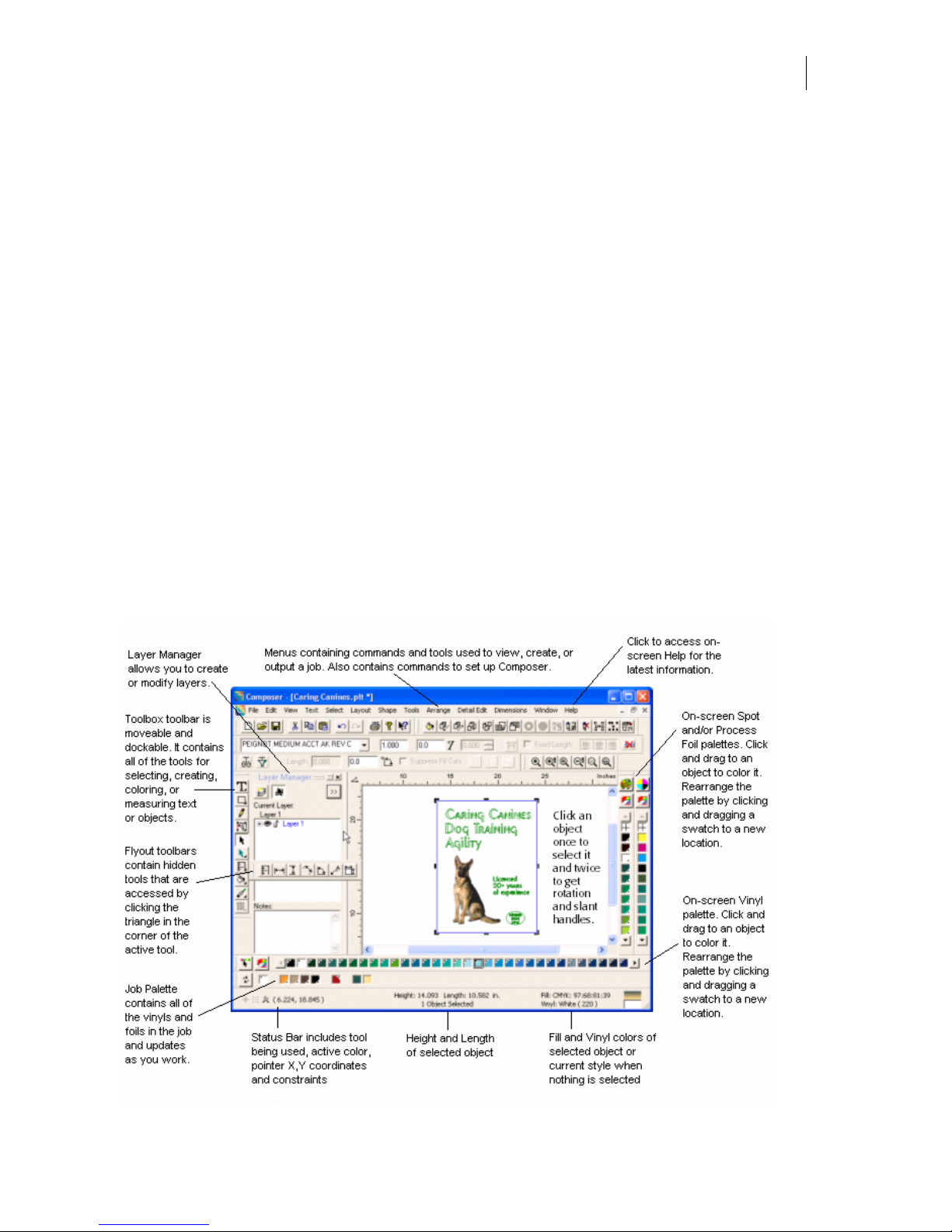
31
Chapter 5:
Setting Up Composer's Work Surface
OMEGA’s Composer program is where you design jobs. Composer allows you to customize
the work surface and change your view of the job while you are working on it.
Composer work surface
On the left side of the work surface is the Toolbox toolbar and the Layer Manager (if active),
across the top are the main menu selections. The foil palettes are available on the far right of
the work surface and the vinyl palette displays along the bottom. The Job Palette which
contains the vinyls and foils in the job displays below the vinyl palette or can be docked in a
different location.
Scroll bars are always present and the work surface is unlimited. The size of the window does
not automatically grow to always display the entire job. Click and drag operations that bump
into the side of the window scroll automatically to reveal additional work surface area. The
frame is now a reference frame only and is used to define the size of the job in Tools >
Options > Layout. Its visibility is configurable in Tools > Options > View.
Page 46

Chapter 5:
32
Setting Up Composer's Work Surface
Displaying information
In Composer, you have the choice to display or hide the status bar, the rulers, and warnings.
In most cases, you will want to see the status bar information which includes:
♦ X and Y coordinates of the pointer
♦ The tool being used
♦ Icons for constraints that are turned on (On Axis, Grid, and Snap to Guidelines shown
left to right in the illustration)
♦ Measurements related to the tool being used
♦ Current style
Set the display of this information in Tools > Options.
To display the status bar and/or rulers
1 Click Tools > Options > View.
2 Turn on the Status Bar and/or Rulers check boxes.
To display warning message boxes
1 Click Tools > Options > General.
2 Turn on the Display Warning Message Boxes check box.
Opening, displaying, and moving toolbars
Toolbars are flyouts, dockable, and moveable. To set the preference of toolbars you want to
display when Composer opens, click Tools > Options > View and turn on the toolbars.
To open and display toolbars
1 Click View > Toolbars to open the Toolbars dialog box.
2 Turn on the toolbars to display.
3 Click OK.
Tip: If the Toolbox toolbar is open, click and hold on the icon or
click the triangle in the lower right corner of the icon to open the flyout toolbar.
Tip: You can also open the Toolbars dialog box by right-clicking in an empty area of a toolbar
and selecting View Toolbars.
To move a toolbar
Click the toolbar and drag it to a new location.
Note: Toolbars do not resize when they are moved. If a toolbar is dragged to a location that
does not have room for it, the end of the toolbar may be off the screen.
Page 47

33
To return the toolbar display to the original preferences
Click Tools > Options > View and turn on Restore Original Position.
Window controls
Composer allows you to have multiple windows open at the same time. These can be either
different files or the same file in two windows. One reason to have the same file open in two
windows is to work in wireframe in one window and display the job as filled in the other
window.
To open multiple windows
1 With a file already open, click File > New or Open to open another window.
2 Click Window > Cascade, Tile Horizontally, or Tile Vertically to display all open
windows.
To open the same file in multiple windows
1 With a file already open, click Window > New Window to open another window
with a copy of the file in the new window.
2 Click Window > Cascade, Tile Horizontally, or Tile Vertically to display all open
windows.
To move between open windows
Click anywhere in a window to make it the active window.
To close a window
Click in the left corner of the title bar and then click Close.
To view open files in Windows
With files open, click Windows to see the list of currently open files in the OMEGA program.
Tip: If you have multiple windows open and minimized, click Window > Arrange Icons to line
them up across the bottom of the Composer window. Windows that are minimized are not
affected by the tile commands.
Sizing the work surface to the design
If you are designing a sign 10' long and 8' high, it is easier to design if the work surface
resembles the borders of the sign. The way to do this is to use a reference frame.
Adding a reference frame
You can place a reference frame on the work surface to simulate the borders of the sign.
Create the design elements either in the reference frame or outside of it, and then move them
around in the reference frame until you have the design layout that you want. The following
procedure places the reference frame on the work surface and sets the default size for new
future reference frames.
Page 48

Chapter 5:
34
Setting Up Composer's Work Surface
To add a reference frame
1 Click Tools > Options > View.
2 Turn on Reference Frame and then click Apply.
3 Click the Layout tab.
4 In the Default Frame for New group box, enter the X and Y coordinates for the lower
left corner.
5 Turn on Enter Size as Height and Length.
6 Enter the length and height of the sign in inches (for example, 120" for a 10' sign).
Tip: Normally, you will want to work on the largest work surface possible. To have Composer
open with the window at maximum size, click Tools > Options > File and turn on the Maximize
Work Area at Startup check box.
Changing the size of the frame
Use the Change Reference Frame dialog box to change the size of an existing reference frame
on the work surface. Choose the Absolute option and enter the lower left and upper right
corner coordinates. To add space to the size of the working area, choose the Incremental
option. The coordinate boxes are reset to .000. Enter the amount that you want to add to the
existing work surface size.
To change the size of the frame
1 Click Edit > Change Frame to open the Change Reference Frame dialog box.
2 Choose Absolute or Incremental sizing.
3 Enter the corner coordinates.
4 Click OK.
Tip: As you move shapes and text on the work surface, if you click Tools > Options > View,
then turn on Enable Autoscrolling, the work surface automatically scrolls so that you can
continue to see it if it “moves” beyond the work surface border. If you turn this check box off,
you can move the shape off the work surface and it is hidden under the border of the work
surface.
Page 49

35
Aligning an object in the working area
Use the Change Baseline command to automatically align an object in the working area
exactly horizontal (parallel to the bottom of the working area). This is especially useful if you
accidentally tilt an object when digitizing it.
The left end of the baseline is always located at the 0,0 position and the baseline is always
exactly horizontal in the working area. If you need to align an object to the exact horizontal,
turn on the baseline checkbox in Tools > Options > View tab, then turn on the Change
Baseline command in Edit > Change Baseline. When the Composer message appears asking if
you want to move the left baseline point, click Yes. Move the pointer to the left end of the
object and click to set it. Click Yes again when asked to move the right baseline point, then
move the pointer to the right end of the object and click to set it.
Note: Always change the baseline before adding text or other design elements to the job
because changing the baseline rotates all objects in the working area.
Using the Natural Layout option
In his book, “Mastering Layout”, Mike Steven describes a formula for laying out a simple
sign. The formula attempts to make the sign layout appealing to the viewer and includes both
margin and copy space. The Natural Layout option in Composer makes use of this formula
when creating a sign template. Guidelines delineate areas in which the user creates text and
graphics for a pleasing sign.
To use Natural Layout
1 Click Tools > Natural Layout to open the Natural Layout Dimensions dialog box.
2 Enter a value for the sign in Height.
3 Enter a value for the sign in Width.
4 Turn on Create Frame to display the boundaries of the sign. Turn off Create Frame to
hide the sign boundaries.
5 Click OK to return to the Composer work surface to view the Natural Layout
template.
Page 50

Chapter 5:
36
Setting Up Composer's Work Surface
Viewing the design
You can work in the wireframe or filled mode. Filled mode
displays the job with the vinyl and fill colors visible. Wireframe
mode displays objects as outlines. Wireframe can be modified to
suit the way you work through the View menu or on the View tab
of the Tools > Options dialog box. A check mark next to the View
menu option indicates the current mode.
Filled mode
In Filled mode the job displays in its stacking order with its vinyl
and fill colors visible. Hidden objects or layers do not display in
Filled mode. Objects that are filled with the same color as the
background color are not visible in Filled mode.
If you are in the filled mode, there are two options:
♦ Design View displays all visible objects in the job. Hidden
objects do not display.
♦ Output View displays visible objects in the job as they would appear when printed
and cut on a plotter with the excess vinyl weeded away. Hidden objects do not
display.
Fill stripes
You can specify the number of stripes in the fill on the View tab of the Tools > Options dialog
box. More stripes (about 50 or more) make the fill appear smooth, while fewer stripes (10, for
example) make the fill appear coarse. While more stripes may offer a more pleasing on-screen
appearance, it takes longer to fill the shape. The stripes only affect what you see on the
computer monitor. They do not affect printed output.
Note: When using OMEGA CS, the Filled Mode defaults to Vinyl only.
Tip: If you are in Filled mode and nothing displays, check to see if you have duplicate shapes
placed directly on top of each other. Duplicate shapes can cause them to disappear in Filled
mode (although wireframe shapes do display).
Wireframe mode
There are four methods of drawing wireframes which can be set in the View menu or on the
Tools > Options > View tab. Objects or layers that are hidden do not display in any
Wireframe modes.
♦ Single Color causes all objects to be drawn with a solid line using the wireframe. The
default line color is black but the color can be changed on the Tools > Options >
General tab.
Page 51

37
♦ Cut Print Colors causes all objects to be drawn with a solid line using the Cut Only,
Print Only, and Cut Print colors. The default colors can be set on the Tools > Options >
General tab.
♦ Vinyl Colors causes the objects to be drawn with a solid line using their assigned
vinyl colors. If the currently assigned background color is the same as an object's vinyl
color then that object will not be visible in Vinyl Colors mode.
♦ Fill Colors causes the objects to be drawn as wireframes in their assigned fill colors.
Gradient fills are drawn using a dotted line. If an object has a process color gradient
fill the first color of the fill is the wireframe color. If an object has a spot gradient fill
the wireframe color is the highest percentage tint. Clear fills (or no fills) are drawn
using a dashed line in the vinyl color. If the currently assigned background color is the
same as an object's filled color then that object will not be visible in Fill Colors mode.
Image Placeholders are drawn differently depending on their color. Process color image place
holders use a dotted black line; spot image place holders use a solid color line in the assigned
spot color.
Small Text is drawn solid in the color that reflects the fill. Gradient fills are drawn as a cross
hatch pattern and clear fills (or no fills) are drawn using diagonal lines.
Tip: There are two Wireframe Modes for Single Color or Cut Print Colors: Finish and Redraw.
See the topic, “View tab” for detailed information on these modes and how to set the default.
Viewing or printing the Wireframe Legend
The rules of wireframe drawing are complex. Click View > Wireframe Legend to access a
chart of the current wireframe settings. Once the Wireframe Legend is open you may print it
on a paper printer using the Print button.
Page 52

Chapter 5:
38
Setting Up Composer's Work Surface
Zooming in or out on the design
Composer provides several ways of zooming in or out on objects. Click one of the Zoom tools
or click View > Zoom > Zoom tool to activate the tool.
Zoom In magnifies the area where you click one level, or the area that you surround
with a rubber band box.
Zoom In One Level automatically magnifies the view one level without clicking the
work surface.
Zoom Out/Select Center reduces the magnification of the job one level centered at the
point that you click on the work surface.
Zoom Out One Level automatically reduces the magnification one level without
clicking the work surface.
Zoom to Selected magnifies the currently selected object so that it fills the work
surface.
Zoom to All resizes the design so that it is in the center of the work surface with a
small border around it. Pressing the Space Bar will also Zoom to All.
Adjusting the level of zoom magnification
In the Options dialog box, you can set your zoom tools to adjust the level of magnification
when zooming. The amount of magnification can be adjusted between 0 (widest zoom) and
20 (tightest zoom). The default level of magnification is 8.
To adjust the level of zoom magnification
1 Click Tools > Options > View Tab.
2 In the Working Area group box use the slider to adjust the Zoom Wider or Tighter.
Alternately, enter a number between 0 and 20, (0 being the widest and 20 being the
tightest).
3 Click OK to return to the Composer work space.
Page 53

39
Setting Preferences using Tools > Options
Use the controls in the Options dialog box in the Tools menu to set up default settings and
behaviors for Composer. The Options dialog box has several tabs listed below that group the
controls for easy access.
♦ General
♦ File
♦ View
♦ Layout
♦ Images
♦ Detail
♦ Text
♦ Palettes
At the bottom of the Options dialog box are two helpful buttons, Apply and Defaults.
♦ Apply – The Apply button in the Tools > Options dialog box (as well as other dialog
boxes) allows you to apply new settings without having to close the dialog box. You
may make multiple changes in different tabs in the Options dialog box and then click
Apply to confirm the changes. Click OK to close the Options dialog box when finished.
♦ Defaults – The Defaults button allows you to restore OMEGA default settings for the
current page or for all pages. When you select the Defaults button a message box
displays. Click Restore All Pages or Restore Current Page to return the settings to the
factory defaults. Click OK to close the Options dialog box.
General tab
The General tab of the Options dialog box contains settings for Composer modes on start-up,
Undo, palette scroll speed, colors and sounds. Click Apply to confirm the settings. Click OK
to return to Gerber factory defaults.
Page 54

Chapter 5:
40
Setting Up Composer's Work Surface
Settings group box
Turn on Emulate OMEGA CS (i.e. vinyl only) to force OMEGA CP (Cut/Print) to display
jobs as vinyl only, thus imitating the behavior of OMEGA CS (Cut Solution).
Turn on Suppress Fill Cuts to create new objects and text that are print only. Suppress Fill
Cuts is also a command in the Arrange Menu. See the topic: Filling without cutlines for
details.
By default Display Warning Message Boxes is turned on to display all
warning message boxes. Turn off this check box so that warning message
boxes do not displayed.
The Use Default Monument Settings on Start check box displays only if you have the
OMEGA Monument option. It is turned on by default.
Undo
You can set the Number of Undo levels from 1 to 100. See the topic: Setting the Number of
Undo operations for details. The default number is 10.
Colors
You can modify the colors assigned to OMEGA objects to suit your needs. In the Colors box,
choose an item from the drop down list. Click Edit Color to display the Selected Color dialog
box. Select a different color from the basic color palette or define a Custom Color. See the
View tab for additional information on wireframe colors.
Sounds
Direct access to the Sound Properties of Windows Control Panel is provided on the General
tab of the Tools > Options dialog box. Click the Edit button to open the Sounds Properties
dialog box. Composer's sound events display at the end of the Events list.
Select a Composer event and choose a sound from the Name drop down list. You can map
custom sounds to specific events by selecting an event, clicking the Browse push button, and
then navigating to any directory that contains WAV files and selecting one.
Palette Scroll Speed
You can adjust the speed at which the vinyl and foil palettes scroll when you press the arrow
buttons at either end of the palette. Click and drag the slide control between Fast and Slow.
The sample palette allows you to test the selected speed setting.
Tablet
Tablets are now installed via the General tab of the Tools > Options dialog box rather than
through GSPSetup. Click the Select button to open the Tablet Selection dialog box. Choose
the correct size tablet and click OK. You must save Preferences to permanently save the tablet
setting. For complete installation instructions and trouble shooting see “Chapter 36:
Digitizing Artwork.”
Page 55

41
File tab
The File tab of the Options dialog box contains settings for Composer modes on start-up and
save options. Click Apply to confirm the settings. Click OK to return to Gerber factory
defaults.
General group box
Turn on Maximize Work Area at Startup to open Composer with the work space maximized
to fill the window.
Turn on Reopen Last File at Startup to open the last accessed file when starting Composer.
When this option is cleared, a new blank file is opened when starting Composer.
Turn on Color Cartoon when Saving Files to display a plot file as a color thumbnail in the
Preview box of the Open, Import or ThumbPrint dialog boxes. Turn off this option to display
the plot file as a wireframe. Color Cartoon is the default setting.
Enter value up to 16 in the Recent File List Contains box to display that number of the most
recently used files in the MRU list of the File menu. See the topic: Most recent file list for
details.
Recent Hot Folder List Contains the number of files in the designated folder that converts
OMEGA plot files to EPS files. You can export the entire file or previously selected objects.
In Mode on New or Open Select choose which tool is active when a new or existing file is
opened in Composer. Choose a tool from the drop down list.
Save Options
Turn on AutoBackup to enable or disable an automatic save of the current file to a temporary
file in a user-selectable folder. You can specify the interval of time between backups from five
to thirty minutes. AutoBackup does not clear the undo stack.
Page 56

Chapter 5:
42
Setting Up Composer's Work Surface
You can specify the location to save the AutoBackup files in the AutoBackup Directory box.
Design Time Tracking
Turn on Enable Tracking to track the amount of time spent designing a job.
Enter the number of Idle Minutes (inactive time in OMEGA) after which to Suspend
Tracking. The default value is 5 minutes. You can adjust this time between and 1 and 120
minutes.
Turn on Track Time Spent in Acquire or Edit Image (Idle Check Disabled) to include this
time in the elapsed time total. Disabling this option excludes this time from the total.
Turn on Enable File Access Logging to keep track of all File > Open and File > Save activity.
The Maximum Log File Size can be set by entering a value between 1 KB and 512 KB. The
default size is 128 KB. When the file reaches maximum size, the oldest information is deleted
as new information is added.
Click View Log File to open the log file in Notepad.
Page 57

43
View tab
The View tab of the Options dialog box contains settings for displaying images, design
creation tools, drawing modes, window settings, and toolbars. Click Apply to confirm the
settings. Click Defaults to return to Gerber factory defaults.
Show group box
Turn on Guidelines to display guidelines on the Composer work surface. Turn off this
option to hide the guidelines.
Turn on Grid to display a layout grid that can be used to align objects. Use the Grid in
conjunction with the constraint tools of the Layout menu to assist and moving objects or
drawing shapes. See the topics: Drawing Shapes and Displaying Information for details. You
can set the size of the grid through the Set Grid command of the Layout menu or on the
Layout tab.
Turn on All Control Points to display the graphical points controlling the shape of a curve.
Turn on the Images option to display actual images rather than placeholders. Alternately,
you can turn on Show images from the View menu of Composer. See the topic: “Viewing
images in the design” for details.
Turn on Templates to display a template object. See the topic: “Choosing the color type” for
details.
Turn on Baseline to display a guideline that is parallel to the bottom of the work surface.
Turn on Reference Frame to display a frame on the work surface that simulates the borders
of a sign. You can alter the size of the frame on the Layout tab.
Page 58

Chapter 5:
44
Setting Up Composer's Work Surface
Turn on Keyboard Rotate Dialog to automatically display the controls for keyboard rotation
when you click Shape > Keyboard Rotation.
Window group box
Turn on Status Bar to display the Status Bar along the bottom of the Composer work space.
The Status Bar includes:
♦ X and Y coordinates of the pointer
♦ Currently selected tool
♦ Icons for active constraints
♦ Measurements related to the tool being used
♦ Current style
Turn on Rulers to display rulers along the top and left side of the Composer workspace.
Turn on Enable Autoscrolling to have the work surface automatically scroll as you move an
object beyond the work surface border. If you turn off this check box, the work surface does
not move when you can move the shape beyond the border of the work surface. You must
use the scroll bars to change the view.
Toolbars
Turn on any toolbars or the Layer Manager to display them in Composer.
Turn on Restore original position to return toolbars to their original position if they are
moved off the work surface or “lost.”
Working Area group box
Wireframe
Turn on Wireframe to set it as the default drawing mode. Turn off wireframe to display
objects in Filled mode as the default.
Wireframe Color
There are four methods of wireframe which can be set in this dialog box or in the View menu:
♦ Single Color causes all objects to be drawn with a solid line using the wireframe. The
default line color is black but the color can be changed on the General tab.
♦ Cut Print Colors causes all objects to be drawn with a solid line using the Cut Only,
Print Only, and Cut Print colors. The default colors can be set on the General tab.
♦ Vinyl Colors causes the objects to be drawn with a solid line using their assigned
vinyl colors. If the currently assigned background color is the same as an object's vinyl
color then that object will not be visible in Filled mode.
♦ Fill Colors causes the objects to be drawn as wireframes in their assigned fill colors.
Gradient fills are drawn using a dotted line. If an object has a process color gradient
fill the first color of the fill is the wireframe color. If an object has a spot gradient fill
the wireframe color is the highest percentage tint. Clear fills (or no fills) are drawn
using a dashed line in the vinyl color. If the currently assigned background color is the
same as an object's filled color then that object will not be visible in Filled mode. Image
Placeholders are drawn differently depending on their color. Process color image
Page 59

45
place holders use a dotted black line; spot color image place holders use a solid color
line in the assigned spot color. Small Text is drawn solid in the color that reflects the
fill. Gradient fills are drawn as a cross hatch pattern and clear fills (or no fills) are
drawn using diagonal lines.
Tip: The rules of wireframe drawing are complex. Click View > Wireframe Legend to access (and
print) a chart of the current wireframe settings.
Wireframe Mode for Single Color or Cut Print Colors
There are two Wireframe Modes for Single Color or Cut Print Colors:
♦ Finish causes the entire selection and everything underneath it to be erased when
moving objects and then redrawn when the object is placed. Finish mode eliminates
the small “holes” that may appear when using nudge to move an object one pixel at a
time.
♦ Redraw is the default and is the wireframe drawing mode as it was in Composer
versions older than OMEGA 2.0.
Filled Mode:
There are two Filled modes that can be set in this dialog box or in the View menu.
♦ Design View displays all visible objects in the job. Hidden objects do not display.
♦ Output View displays visible objects in the job as they would appear when printed
and cut on a plotter with the excess vinyl weeded away. Hidden objects do not
display.
Number of Fill Stripes
In the Filled mode, you can specify the number of stripes in a fill. More stripes (about 50 or
more) make the fill appear smooth, while fewer stripes (10, for example) make the fill appear
coarse. While more stripes may offer a more pleasing on-screen appearance, it takes longer to
fill the shape. The stripes control only affects what you see on the computer monitor. It does
not affect the printed output.
Zoom Wider/Tighter
Use the slider to adjust the Zoom Wider or Tighter. Alternately, enter a number between 0 to
20 (zero being the widest and 20 being the tightest). The default setting is 8. See the topic:
“Adjusting the level of Zoom magnification” for details.
Page 60

Chapter 5:
46
Setting Up Composer's Work Surface
Layout tab
The Layout tab of the Options dialog box contains settings for tool constraints, Reference
Frame settings and Layers options. Click Apply to confirm the settings. Click Default to
return to Gerber factory defaults.
Constraints
Turn on On Axis to allow only vertical or horizontal movement of objects. When adding
dimensions to a job, On Axis should be turned OFF to allow the dimension tools to snap to
nodes.
Turn on Snap to Guidelines to align an object to the closest guideline as the object moves
toward it. This command is turned off if Snap to Grid is activated.
Turn on Lock Guidelines to anchor Guidelines in position. This is helpful when moving
objects while Guidelines display. See the topic: Locking objects for details.
Turn on Snap to Grid to align an object to the closest grid point as the object moves toward
it. This command is turned off if Snap to Guidelines is activated. When Snap to Grid is active
the Grid Value setting is available. Enter a new value to change the size of the grid. The
default setting is 0.100 inches.
Turn on Constrain Cursor so that the tool is affected by any constraints such as On Axis,
Snap to Guideline, and Grid set in the Layout Menu.
Default Frame for New
Define the location and size of a Reference Frame that simulates the borders of a sign. To
display the Reference Frame, turn on the option in the View tab.
Page 61

47
Layers
Turn on Edit All Layers to allow editing on all layers in the job. When this option is disabled,
you can only edit the active layer. The default setting is turned on.
Group Layers when Merging puts all objects on the same layer and into the same group
when merging layers using the Merge Selected Layers or Merge All Layers commands. The
default setting is turned off.
Default Dim Intensity sets the default dim level in a percentage. The default percentage is
50%.
When the Select Object's Layer when Object Selected option is turned on (this is the
default) selecting an object makes its layer the current active layer. Clear the Select Object's
Layer when Object Selected option to be able to select an object without changing the
current active layer. When this option is turned off, you must click a layer name to make it
the active layer.
Box Select or Select Menu Commands Select Layer of gives you the option to choose which
layer becomes the active layer when marquee selecting objects on the work surface, or when
selecting objects using the Select menu. By default, the layer that contains the front-most
object in the stacking order of the selection becomes the current layer. You can choose to
make the layer containing the back-most object the current layer or not to change the current
layer when selecting objects in this manner.
Show Break Group Warning displays a message when you attempt to move part of a group
to a different layer, thus breaking the group.
Show Break Combine Warning displays a message when you attempt to move part of a
combine to a different layer, thus breaking the combine.
Show Release Clipping Path Warning displays a message when you attempt to move only
part of a clipping path to a different layer, thus releasing the clipping path.
Show Recent Smart Edit Warnings displays a message when you attempt to move only part
of a chain of smart edit operations to a different layer, thus saving only the last smart edit
connection.
Show Remove Smart Edit Warnings displays a message when you attempt to move only
part of a smart edit operation to a different layer, thus removing the smart edit connection.
Show Combine Text Warning displays a message when you attempt to combine text with
other shapes that are not on the same layer unless all shapes on the line are selected.
Targets
Show Create Target Layer Warning displays a message when you create targets which
explains that the targets are created on a new layer named Target Layer. Turn on Layer
Manager to view the layer tree.
Show Target Create Time Warning displays a message when an excessive number of shapes
are selected for Automatic Target creation. Warning suggests you select only surrounding cut
shapes to minimize confusion when creating targets.
Page 62

Chapter 5:
48
Setting Up Composer's Work Surface
Images tab
The Images tab of the Options dialog box contains settings for importing and editing images,
Thumbnail settings, and control of temporary embedded images files. Click Apply to confirm
the settings. Click OK to return to Gerber factory defaults.
Color Type
Choose the default Color Type to apply to imported images:
♦ Spot – Choosing Spot changes a full color image into a monochrome image consisting
of tones of the chosen Spot foil. See Default Spot Color below for details.
♦ Process – Choose Process to fill the imported image with Process color foils.
♦ Template – Choose Template to import an image as a Template that can be displayed
but not printed to a thermal printer. (A Template image can be printed on a paper
printer.) A Template is useful when digitizing shapes in images.
Default Spot Color
Default Spot Color is only available when Spot is chosen as the default Color Type. Click
Browse to select the foil palette and then choose the default spot color to apply to an
imported image.
TWAIN Device
Choose a TWAIN device connected to your computer that is to be used by the Scan to Vector
program. Click Select to display available choices for your system.
Image Editor
Choose an Image Editor program to be used when editing an image after it has been
imported into Composer. Click Browse and navigate to an image editing program (such as
MSPaint or Corel PhotoPaint) on your system. See the topic: Editing an image with an image
editor for details.
Page 63

49
Thumbnail
Thumbnail settings affect how images display on your monitor and print on paper. It does
not affect how images output to a vinyl printer.
Choose 1, 4, 8 or 24 Bits per Pixel. The higher the Bits per Pixel the better the image displays.
Low Resolution results in faster screen redrawing. High Resolution displays the original
image not scaled (all dots are shown on the screen). It offers a more accurate appearance but
it increases file size and slows down screen redrawing. See the topic: Changing the resolution
for details.
Turn on Dim All Images so that images in your design display at a percentage of their
originally intensity, allowing you to see the digitizing and detail editing tools. The default
intensity is 50%. See the topic: Dimming an image for details.
In Dim Intensity, enter a percentage at which to display dimmed images.
Temporary Images Files for Embedded Images
OMEGA creates temporary image files to allow GSPPlot – Quick Plot to maintain access to
embedded image files even after Composer is closed. Set the time period (in days) after
which the files will be deleted. The files are cleared when Composer is next launched only if
there are no other instances of Composer running.
To immediately delete the temporary embedded image files, click the Clear Now button. Any
temporary files that are not currently being used are deleted.
Detail tab
The Detail tab of the Options dialog box contains settings for Detail Edit. Click Apply to
confirm the settings. Click OK to return to Gerber factory defaults.
Turn on Retain to maintain a closed object when moving a segment. Turn off Retain to create
two open shapes when moving a segment.
Page 64

Chapter 5:
50
Setting Up Composer's Work Surface
Turn on Use Select Menu's All/Cancel/Reverse to activate Composer's Select menu shortcuts
within Detail Edit, i.e. F2, Select All, F3, Cancel Selection, F4, Reverse Select.
Turn on Warning Beeps to activate audible warning beeps.
Turn on When Joining, Copy Partially Selected Shapes (Via Menu Command “Join
Selected Segments J” Only) to automatically copy detail selected segments and place them
back on top of the original segments. This functionality originally existed in GRAPHIX
ADVANTAGE but often creates open shapes without user knowledge.
Turn on Show Align Points Dialog to automatically display the Align Points dialog box,
which provides controls for placement of points and alignment of curve control points.
Turn on Show Break Apart Dialog to automatically display the Break Apart dialog box,
which provides a warning that each segment of each shape will become a separate shape.
Turn on Show Find Intersections Dialog to automatically display the Find Intersection
dialog box, which provides controls for retaining closed shapes.
Selection Rectangle Handle Size (in) (0): Use the slider control or enter a value between
0.040" and 0.200" to alter the on-screen size of the Detail Edit Selection Rectangle handle. The
shortcut key is 0.
Point Size (1): Use the slider control or enter a value between 0.040" and 0.200" to alter the
size of the Detail Edit point. The shortcut key is 1.
Printer Point Size (in) (2): Use the slider control or enter a value between 0.025" and 0.200" to
alter the size of the symbols that are used to draw points on a printer. The shortcut key is 2.
Selection Distance (in) (3): Use the slider control or enter a value between 0.025" and 0.200"
for the greatest distance that the mouse is from a point of line segment to select it. The
shortcut key is 3.
Snap to Distance (in) (4): Use the slider control or enter a value between 0.025" and 0.333" for
the greatest distance an object can be from a guideline or grid point and still snap to it. The
shortcut key is 4.
Super Nudge Distance (Shift) (in) (5): Use the slider control or enter a value between 0.001"
and 0.333" for the distance an object is moved when using the keyboard Shift + arrow keys.
(Normal Nudge distance is 1 pixel.) The shortcut key is 5.
Join Distance, for Join Selected J (in) (6): Use the slider control or enter a value between
0.100" and 1200.00" for the greatest distance two points can be apart and be joined with the
Join selected command. The shortcut key is 6.
Duplicate Point Distance (in) (7): Use the slider controls or enter a value between 0.000001"
and 0.020000" to set the maximum distance you can be away from another point, and still be
considered the same point. The shortcut key is 7.
Paste/Duplicate Offset Distance (in) (8): Use the slider control or enter a value between 0
and 1200.00" for the distance that a pasted object is offset from the original. A 0 setting results
in objects being placed directly on top of each other. The shortcut key is 8.
Minimum Move Distance (in) (9): Use the slider control or enter a value between 0 and
0.260" for the distance a mouse moves from the original button down location before the
move actually begins. The shortcut key is 9.
Page 65

51
Text tab
The Text tab of the Options dialog box contains settings for Fonts and Layout for text. Click
Apply to confirm the settings. Click OK to return to Gerber factory defaults.
Font group box
Default Font for Enter/Edit Text Box
Choose a default font to use in the Enter/Edit Text Box from the drop down list. Also enter a
default height and slant.
Show Most Recently Used Fonts
Turn on Show Most Recently Used Fonts to show the last chosen fonts at the top of the
Selection Font combo box in TOWS. Turn off this option if you do not wish to show the fonts
at the top of the list. See the topic: Choosing a font in TOWS for details.
Show Font not in Font List Warning
Turn on Show Font not in Font List Warning to display a warning if the active font in TOWS
is no longer available because of the current font filter settings. See the topic: Limiting and
displaying available font choices in TOWS for details.
Layout
Choose the layout defaults for justification of text as you enter it. See the topic: Entering and
justifying text in lines or columns for details.
♦ Justification – Choose Center, Left, or Right for layout when entering text.
♦ Horizontal – Choose Left to Right or Right to Left for layout when entering text.
♦ Vertical – Choose Top to Bottom or Bottom to Top for layout when entering text.
Line Rotation
Enter a default angle of rotation to apply to text as it is entered. The angle must be between 80 and 180 degrees.
Page 66

Chapter 5:
52
Setting Up Composer's Work Surface
Palettes tab
The Palettes tab of the Options dialog box contains settings for background, vinyl and
process palettes. Click Apply to confirm the settings. Click OK to return to Gerber factory
defaults. See the topic: Setting the default for background and vinyl for details.
Default Vinyl Color
Choose a default vinyl palette to display when opening a new file in Composer and then
choose a default color from that palette. The chosen color becomes the vinyl of the Current
Style, which is assigned to all newly created objects. See the topic: Setting the current style for
details.
Turn on Use this vinyl as a default on File Open to use the default vinyl when opening
existing plot (PLT) files.
Default Background Color
Choose a default vinyl palette and then choose a default color from that palette for the
background color. The chosen color displays as the Composer background.
Vinyl Palette
Choose a default vinyl palette to display along the bottom of the Composer work surface. If
you have Use Default Monument Settings on Start turned on in the General tab of Tools >
Options, the vinyl palette 220 – GA3.5 Colors is always used. You can not change the vinyl
palette when Use Default Monument Settings is active.
Process Palette
Choose a default process palette to display on the Composer work surface from the drop
down list. You can select from standard Gerber palettes or any custom process palettes that
you have created.
Page 67

53
Note: If you have the OMEGA Monument option, the default Monument settings are loaded
on start up. When Use Default Monument Settings on Start is turned on (on the General tab)
the default vinyl palette is 220 – GA3.5. You can change the Default Vinyl Color and the
Default Background Color, but you must choose a color within this palette. If you attempt to
change the Default Palette, OMEGA automatically returns to the Monument settings, even if
you click Preference.
Page 68

Page 69

55
Chapter 6:
Using Layers
When working with complex signs it is often difficult to organize and control all of the
objects on the work surface. Small objects can get “lost” behind larger objects. Selecting and
editing objects can become cumbersome as the number of shapes increases. Layers provide a
way to manage complicated jobs.
You can choose to work with layers. Working with layers is like drawing on overlapping
pages in a book where job elements are separated onto their own pages. Each layer can be
selected, displayed, or locked to prevent further design changes. Layers can be rearranged in
front or behind other layers, and output separately. For example, all images can be placed on
one layer and all text can be placed on another layer. Each of these layers can then be treated
independently while remaining part of the same job.
Using layers, you can create a single job that contains variations of a design in one PLT file.
For instance, you can keep the designs for building, entrance, and vehicle signage in the same
file on different layers.
Vinyl only jobs can now be designed more easily using layers and the capabilities of OMEGA
2.5 or higher:
♦ To Front and To Back commands allow each vinyl-only job element to be placed where
they need to be.
♦ Stacking order permits jobs with multiple vinyls to display correctly when objects
overlap. The same vinyl color can be in front and in back of other objects. (Previously
Composer attempted to put smallest shapes in front of larger shapes even if the final
order was not correct. In addition, multiple shapes of the same vinyl color could not be
both in front and behind other objects.)
♦ When using layers, the same vinyl color can reside on different layers, offering display
and stacking flexibility.
♦ Vinyl only text combines automatically.
♦ Vinyl-only objects of the same color such as shapes or imported objects must be
combined to knock one shape from another.
Tip: If printed shapes are added to a vinyl only job, OMEGA displays in a Print Order mode
rather than a Vinyl Only mode. Vinyl-only objects will knock out automatically, but you loose
the To Front and To Back stacking flexibility mentioned previously.
Page 70

Chapter 6:
56
Using Layers
Rules for designing with layers
♦ The layers capability is turned OFF by default. To use layers, you must turn on the
Layer Manager in View > Layer Manager. You can change the default setting on the
Tools > Options > View tab.
Note: If you open a plot file with layers and Layer Manager is turned off, the layers still exist
even though you can not see them. If you encounter difficulty viewing or selecting objects
turn on Layer Manager using the View menu.
♦ Each new Composer job opens with one layer known as the Layer 1.
♦ Jobs designed in previous versions of OMEGA open onto a single layer which has the
same name as the plot file.
♦ Click the New Layer button on the Layer Manager or select New Layer in the Layer
Menu to add a layer to the job.
♦ The top layer is the foremost layer in the job and is in front of all other layers.
♦ To design on a particular layer, select the layer to make it active.
♦ It is helpful to position a design at the 0,0 point on the Composer work surface so that
it is also positioned at that location in GSPPlot. To move to the 0,0 location, Select All
and click Shape > Absolute Move. Enter a 0 in the New Location X, Y box and click OK
to move the lower left corner of the selected objects to 0,0 on the rulers.
♦ Rearrange layers by dragging the layer above (in front) or below (in back) other layers
in the Layer Tree.
♦ Hide or display layers by clicking the eye icon or choosing the Show or Hide
commands in the right-click menu. Hidden layers can still be output. Show or Hide all
layers using the Show All Layers or Hide All Layers commands in the Layer Menu.
♦ Lock or unlock layers by clicking the lock icon or by choosing the Lock or Unlock
commands in the right-click menu. When layers are locked, you cannot select or edit
Page 71

57
objects on that layer. Lock or unlock all layers simultaneously using the Lock All
Layers or Unlock All Layers commands in the Layers Menu.
♦ Expand or collapse layers in the Layer Tree by clicking the +/- icon. Use the Expand
All Layers or Collapse All Layers options from the Layer Menu to open or control all
layers at once.
♦ To dim a layer, right-click the layer and choose a dim percentage.
♦ To rename a layer, choose Rename Layer from the Layer Menu or select an already
highlighted layer and type a new name.
♦ To delete a layer, choose Delete layer from the Layer Menu or select a layer and press
Delete on the keyboard.
♦ Merge layers into a single layer using the Merge Selected Layers or Merge All Layers
commands in Layer Menu. Layers that are hidden or locked cannot be merged.
♦ Layers can be grouped when merging by turning on Group Layers when Merging in
the Layer Menu.
♦ Copy layers using the Duplicate layer command in the Layer Menu.
♦ When importing maintain existing layers or flatten them to a single layer by choosing
the option in the Import dialog box.
Rules for modifying objects on a layer
♦ Within each layer (or in a single layer job) objects are also organized in stacking order.
An object at the top of the stack is in front of other objects below it in the stack.
♦ Select the object on the work surface and it is selected on the Layer Tree. Select objects
by clicking the name in the Layer Tree and it is automatically selected on the work
surface.
♦ Use Shift+click and Ctrl+click to select multiple objects.
♦ Click a layer and then choose Select All in the right-click menu to select all objects on
that layer.
♦ Rearrange objects within a layer by dragging them above (in front) or below (in back)
other objects.
♦ Use the Arrange commands: In Front of, In Back of, To Front, To Back, Front 1, or Back
1 to reorder objects. These commands are found in the Arrange menu or Arrange
toolbar, or by right-clicking an object and displaying the context menu.
♦ Move objects onto a new layer by dragging them to the new layer or cutting and
pasting them to a new layer. Use the Paste Back In Front or Paste Back In Back
commands in the right-click context menu for more control.
♦ When creating a clipping path, objects in the clipping set must be on the same layer.
Page 72

Chapter 6:
58
Using Layers
♦ Multiple objects on different layers cannot have shape effects such as: Outline,
Shadow, Distortion, Warp, or other Effects applied to them. Either move objects to the
same layer or handle each layer separately.
♦ Smart Edits cannot be performed if original objects and results are moved to different
layers. For example, if text is shadowed on Layer 1 and then the shadow is moved to a
different layer, the shadow can no longer be smart edited.
Using the Layer Manager
The Layer Manager is a powerful tool that allows you to create or modify layers. The Layer
Manager includes commands to create, hide, dim, lock, copy, merge or delete layers. You can
reorganize layers and the objects that they contain by dragging and dropping them in the
Layer Manager window. You can also select, move, copy, and delete objects contained on
layers using the Layer Manager.
The Layer Manager can be floating or docked on the Composer work surface. When docked,
you can change the width of the window by clicking and dragging the divider bar between
the window and the Composer work surface. When floating, you can resize
the Layer Manager by clicking and dragging any side or corner. Within the
Layer Manager window is the Layer Tree control and the Notes text box.
Layer Tree
The Layers Tree displays all of a job's layers and their contents. The Layers are
shown in stacking order with the topmost layer at the top of the tree. Layers i
descending order in the tree reflect the stacking (front to back) order of the
job. In the illustration, Layer 2 is the top layer and in front of the layers below
it. Layer 1 is the bottom layer and behind the layers above it in the Layer Tree.
The current layer is indicated above the Layer Tree.
Each layer can be expanded to show its contents or collapsed to hide the
contents by using the + and – buttons. To expand or collapse all layers, use the
Expand All or Collapse All commands in the Layer Menu.
Layers can be visible or hidden by clicking on the eye icon. Hiding artwork
allows you to concentrate on a portion of a job without other objects interfering
with it. You can also show/hide a layer by selecting it and choosing the Hide
or Show command from the right-click menu. To hide or make all layers visible
use the Show All or Hide All commands in the Layer Menu. Hidden objects or
layers can not be selected.
Layers can be locked and unlocked by clicking the lock icon. When a layer is
locked you cannot select or edit objects on the layer. Locking a layer is similar
to locking all objects in the layer individually. You can also unlock/lock a layer
by selecting it and choosing the Lock or Unlock command from the right-click
menu. To lock or unlock all layers use the Lock All or Unlock All comma
the Layer Menu. Select all locke
d layers using the Select Locked Layers
n
nds in
Page 73

59
command in the Layer Menu.
Displaying object properties in t
The Layer Tree now displays detaile
he
d
object properties for each item in the tree
including vinyl, fill, and stroke
information. This information can
viewed by holding the mouse over an
object in the laye
r tree which causes a
yellow tip box to display the entire line
of information.
Alternately you can ex
pand the width of
the Layer Manager to accommodate the
full width of the line.
Layer Tree
Object Properties display from left to right in the following order:
♦ Object type: Image – file name, Shape, or Text – first ten letters
♦ Vinyl type: Color and vinyl name
♦ Fill type: No fill, Clear fill, or Solid – color name and tint percentage if spot or
Spectratone, Linear – color names and tint percentages if spot or Spectratone, or
Radial – color names
Stroke type: No stroke, Clear stroke, or Solid – color name and tint percentages if
♦
spot of Spectratone
and tint percentages if spot or Spectratone
Page 74

Chapter 6:
60
Using Layers
Tip: Turning on Object Prope
rties can reduce the performance of Composer as the Layer Tree
is refreshed with object information. Turning off Object Properties can improve the
Composer's performance.
Selecting layers and objects
Click a layer or object name to select it. Use the Windows Shift+click and Ctrl+click to select
multiple layers or objects. If you select one object of a group or combine, all obje
members of the group or combine are selected in the layer tree.
When selected, the layer name displays in the Current Active Layer color. The default color is
blue and can be changed on the General tab of the Tools > Options dialog box.
On the Layout tab of the Tools > Options dialog box you can alter how the current layer is
selected. Clear the Select Object's Layer when Object Selected option to be able to select an
object without altering the current active layer. When this option is turned off, you must click
a layer name to make it the active layer.
cts that are
When the Select Object's Layer when Object Selected option is turned on (this is the
default) you have the option to choose which layer becomes the active layer when marquee
selecting objects on the work surface, or when selecting objects using the Select menu. By
default, the layer that contains front-most object in the stacking order becomes the current
layer. You can alter how the current layer is chosen on the Layout tab of the Tools > Options
dialog box.
When objects are selected or deselected in the Layer Tree they are also selected or deselected
on the Composer work surface (and vice versa). When selected, an object name is highlighted
in the Layer Tree and the object becomes selected on the work surface.
Page 75

61
Select All
The Select All command in the right-click context menu provides an easy way to select all of
the objects on a particular layer. Any prior selection is cleared. If one or more objects on the
layer are locked, all objects are selected but surrounded by X handles to indicate that there is
a locked object in the selection.
Select Locked Layers
Select Locked Layers selects all layers that are locked in the job. You can then hide, merge, or
delete them. When there are no locked layers in the job, the command is unavailable.
Locating objects and layers in the Layer Tree
Use the Locate Object and Locate Layers command to quickly find an object or layer in the
Layer Tree. Select and right-click an object on the work surface to display the context menu.
Choose the Locate object or Locate Layer command. The item or layer on which it is located is
scrolled into view o re than one object is
selected then the front- stacking order is located.
on the Layer Tree and blinks f r several seconds. If mo
most object in the
Page 76
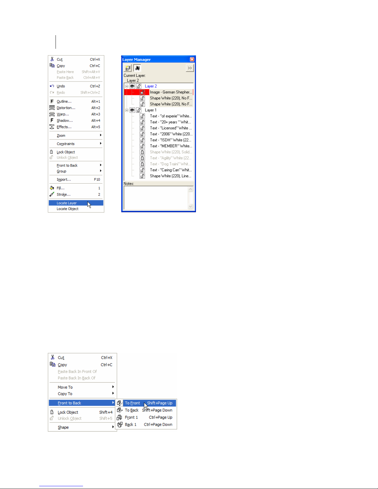
Chapter 6:
62
Using Layers
Changing the order of objects and layers in a job
The stacking order of objects and layers in a job corresponds with the order of the objects in
the Layer Tree. You can reorder the layers or objects on layers in several ways:
Layer Tree
Click and drag objects or layers to their new
object to a new position above it in the Layer Tree positions it in front of the target layer or
object in the job. Dragging a layer or object to a new position below it in the Layer Tree
positions it behind the target layer or object in the job.
Right-click context menu
Reorder objects on a layer by right-clicking the object and selecting a command from the
context menu. The context menu command can apply to multiple objects or layers that are
selected.
position in the Layer Tree. Dragging a layer or
Page 77

63
Arrange menu commands/Arrange toolbar
Reorder objects on a layer using the Arrange menu commands or the Arrange toolbar.
To Front, To Back, Front 1, and Back 1 commands only work on the layer on which the object
resides.
The In Front Of or In Back Of commands in the Arrange menu allows you to move the
selected object to a different location on the work surface. Selecting one of the commands
turns the cursor into a target arrow. Click a target object on the work surface and the selected
object is moved in front of or in back of it in the stacking order. To escape the command
without moving an object, reselect the command from the Arrange menu to clear the check
mark, press the Esc key, or right click and select End In Front of (or In Back of) command.
Paste Back in Front Of or Paste Back in Back Of
After cutting or copying an object you can choose to paste it back in
the same position on the work surface either in front or in back of any
object in the stacking order. Paste Back in Front Of and
Back Of is available when you select and object in the L
Paste Back in
ayer Tree and
right click to display the context menu.
Moving Smart Edit objects to a different layer
When moving objects that result from any smart edit operation such as text blocks, combines,
groups, warp or distortion results to a different layer, you must select all objects involved to
Page 78

Chapter 6:
64
Using Layers
edit results you will be warned that the Smart Edit links will be broken.
retain the Smart Edit attributes. If you attempt to move partial blocks of text or partial smart
When creating a job using a series of Smart Edit operations, moving partial results to a
different layer results in warnings. Take note of the following example:
This border consisting of six rectangles was generated using Repeats and Merge. The three
rectangles on the left were modified using Distortion. The three rectangles on the right were
modified using Warp.
If you attempt to move only one of the rectangles to a different layer, the following warning
displays:
If you attempt to move all of the results of the Distortion to a different layer, you will
maintain only the most recent Smart Edit connection (in this case – Distortion). The
connection to Repeats/Merge Smart Edit is severed. The following warning displays:
Page 79

65
Moving combines and layers
Combines must reside on the same layer.
Combined shapes
create this object.
If you attempt to move part of a combined group to a differe
combine
and the following warning displays.
nt layer you will break the
Turning warnings on and off
The layers warning
can be reactivated (or deactivated) on the L
default they are turned on.
boxes can be turned off using the checkbox in each warning box. They
ayout tab of the Tools > Options dialog box. By
Manipulating objects using the Layer Tree context
menu
You can manipulate an object via the Layer Tree instead of
using the work surface. Select an object in the Layer Tree
and right click to display the context menu. Select Shape and
choose one of the Shape menu commands including: rotate,
size, move, slant, and flip.
You can also Smart Edit an object by double clicking it in the
Layer Tree to open the o
function
or Repe
used to create the object, such as the Border, Warp,
ats dialog box.
pen the dialog box of the last
Page 80

Chapter 6:
66
Using Layers
Dimming layers
Dimming objects on a layer makes it easier to see objects in f
it on the work surface. Layers and their objects can be dimmed t
preset dim levels b
level. The Dim menu is accessed by selecting a layer and then right
clicking.
To dim a layer, choose a preset percentage or the Default dim level
from the cascading menu.
Tip: You can set the User Default dim level via the Layout tab of the Tools > Options dialog
box. The factory set Default Dim Intensity is 50% and any percentage between 0 and 100%
can be entered.
etween 10 and 90% or to a preset Default dim
ront of
o
Notes
The Notes portion of the window provides an area to enter
information about the selected layer. The maximum number of
characters is 511.
Merging notes
When layers are merged, the notes are merged and the top layer's
notes appear first in the window. If the combined notes exceed 511
characters, any notes beyond th maximum limit are discarded.
Using the Layer M
At the top of the Layer Manager is the Layer Menu flyout button
which displays the Layer Menu. The menu contains many commands
associated with layers.
e
enu
Page 81

67
New Layer command
Creates a new layer at the top of
layer is named Layer # where # i
the stacking order and in front of all existing layers. The
s the next unused layer number. The new layer automatically
becomes the active layer.
You can also create a new layer by clicking the New Layer button at the top of the
Layer Manager.
Delete Layer command
Deletes the currently selected layer. The layer immediately above the deleted layer becomes
the active layer.
You can also delete a selected layer by pressing the Delete key on the keyboard.
Rename Layer command
Allows you to rename the current layer to a unique name up to 63 characters long. You can
also select an already selected layer to put it in rename mode.
Merge Selected Layers command
Merges the objects on the selected layers into the last selected layer. The stacking order
within each layer remains the same, but the overall stacking order may change if the layers
were not adjacent before the merge. The screen is redrawn to reflect the new stacking order.
Merge All Layers command
Merges all layers
hidden or locked cannot be merged and you will see the following message:
into the top layer. The stacking order remains the same. Layers that are
Page 82

Chapter 6:
68
Using Layers
Duplicate Layer command
Creates a copy of the selected layer and inserts it in front of (on top of) the original layer. The
copied layer is named Layer X Copy (followed by a number is there is already a copy of the
Copy, Layer 1-2 Copy). Objects on the new layer are offset slightly from the layer, i.e. Layer 1
originals for easy identification. The copied layer becomes the active layer.
This copy offset distance is set in the Detail tab of the Tools > Options dialog box using the
Paste/Duplicate Offset Distance control. The default setting is 0.150 inches.
Lock All Layers/Unlock All Layers
Lock All Layers simultaneously locks all layers in the job. Unlock All Layers unlocks all
layers in the job.
Hide All Layers/Show
All Layers
Hide All Layers simultaneously hides all layers in the job. Hidden layers can still be output.
Show All Layers simultaneously displays all layers and their objects
.
Expand All Layers/Collapse All Layers
Expand All Layers displays all objects on all layers. Collapse All Layers hides the list of
objects on all layers so that only the layer names display.
Edit All Layers
Edit All Layers is turned on by default. When active, you can select or edit objects on any
layer. When this option is turned off, you can only select or edit objects on the active layer.
You can deactivate/activate this option by clicking the Edit All button at the top of the Layer
Manager. Change the default setting on the Layout tab of the Tools > Options dialog box.
Page 83

69
Grouping objects when merging
Objects on a layer can be automatically grouped before layers are merged. Grouping
Layers
when Merging is controlled on the Layout tab of the Tools > Options dialog box. By default
this option is turned off and objects are not grouped when layers are merged.
Object
Object P Properties dialog box where you can choose
Properties…
roperties opens the Layer Tree Object
what color information to display including: vinyl, fill, and stroke.
Page 84

Chapter 6:
70
Using Layers
Print Order and Layers Overview
The addition of layers to Composer provides new ways to organize, design, and view your
job. You can choose to work with multiple layers or to work on a single layer as done in
previous versions
using layers in GSPPlot. If a job is designed with layers in Composer, it can be output b
layers or without layers (flattened or merged) in GSPPlot.
There are several ways to design and output with layers in OMEGA:
1 Design on a single layer in Composer, and output as a single layer from GSPPlot.
If jobs are done in this manner, the design, print order, and output will be very
similar to previous versions of OMEGA. Composer and GSPPlot defaults are set f
design on a
2 Design with layers in Composer and output as a single layer from GSPPlot.
This
method allows for design advantages of layers in Composer but traditional ou
from GSPPlot. See below for a listing of lo
flattened to a single layer for output.
3 Design with layers in Composer and output by layers in GSPPlot. When
outputting by layers from GSPPlot, each layer behaves as a single job. See additional
in
formation in “Understanding Print Order in GSPPlot” later in this document.
of OMEGA. You can choose to design with layers in Composer and output
y
or
single layer allowing for an easy transition into the new layer capability.
tput
cations where layers can be merged or
Layered jobs can be flattened or merged in Composer:
1 ers from the Layer menu. The job will th
Composer you can dynamically switch between layered and flattened print order
In Composer, choose Merge All Lay en reside
a single layer. Once layers are merged in this manner the job cannot be ou
la
yers.
tput by on
2 In
us
ing the Output By Layer checkbox in the Print/Output Order dialog box. Any
changes that were made to the print order before switching to a different typ
e are
discarded.
Layered jobs can be flattened or merged in GSPPlot:
1 The GSPPlot Print Options dialog box also has an Output By Layers checkbo
the Output by Layer checkbox is turned on, GSPPlot uses a layered Print Ord
job has layers). When this option is turned off, the Print Order is flattened to a single
layer. Any manual changes to the Print Order that were made in Composer are
discarded.
2 In GSPPlot, the Select Colors dialog box now includes layer control and information.
You can dynamically switch between a layered or flattened Print Order using the
Output by Layers checkbox. You can also select which layers to output or merge
selected layers from this dialog box.
x. When
er (if the
Page 85

71
Under
A vinyl co
standing Print Order in Composer
lor can be assigned to objects on different layers and each layer may have different
foils assigned to that vinyl. You could also have the same foils in a different stacking
a different layer.
The Print
/Output Order dialog box in Composer offers the flexibility of working wit
layered or flattened Print Order if your job has layers. The default is a flattened (singl
Print Order. Any manua
l changes that were made to the Print Order before switching
different type are discarded. Click Arrange > Print/Output Order to open the dialog
Because each layer behaves like a separate job, each layer has a separate Print Order w
can be rea
Order dia
rranged. Foils cannot be moved from one layer to another in the Print/Out
log box.
The Rebuild button in the Print/Output Order dialog box returns the foil order f the
selected vinyl to the original st previous changes are
acking (front to back) order. Any
discarded.
Click a vinyl to
display the list
gned to it.
assi
Rearrange the
dragging and
dropping or
using the Up or
n buttons.
Dow
of foils
vinyl by
Flat Print/Output Order
order on
h
e layer)
to a
box.
put
o
Clear the Output
by Layer
check
fl
Order
Rearrange the
foils by drag
and dropping in
the list or by
selecting a foil
and using the Up
or Down
buttons.
Clic
returns the Pr
Order for the
selected vinyl to
the original
stacking orde
Unsele
are not affected.
hich
box to
atten the Print
ging
king Rebuild
int
r.
cted vinyls
Page 86

Chapter 6:
72
Using Layers
Ch
oose which
laye
r to display
fr
om the drop
down list.
Cli
ck a vinyl to
disp
lay the list
of foils
assign
ed to it.
Rearrange th
dragging and
dropping or
using the Up or
Down buttons.
vinyl b
e
y
Layered Print/Output Order
When working with Print Order in Composer consider the following:
♦ You can access the Print/Output Order dialog box (via Arrange > Print/Output
Order) even if there are no objects in a job. This allows you to set Print Order
preferences.
Turn on the
Output by Layer
checkbox to use
a layered
Order.
R
earrange the
foils by d
and droppi
the list or by
selecting a foil
and using the Up
or Down buttons.
Clicking R
returns the Print
Order for the
selected vinyl on
the selected
layer to the
original stacking
order. Unselected
vinyls and layers
are not affected.
Print
ragging
ng in
ebuild
♦ New files created in Composer are based on the type of Print Order preferenced in the
Print/Output Order dialog box. The factory default Print Order is flattened (single
layer). The Output by Layer checkbox is not checked.
♦ Legacy files open with a flattened Print Order so that you can work with them without
modification.
♦ When
using layered Print Order, a vinyl color can appear only once per layer but more
than once in the job's print order if it is assigned to objects on different layers
When flattening the Print Order of a job that has layers, each vinyl color appears onc
♦ e
with all of its associated foils regardless of the o
♦ The Rebuild button
selected vinyl to the
in the Print/Output Order dialog box returns the foil order of the
original stacking (front to back) order. Previous changes are
riginal layer assignments.
discarded.
♦ If you have a layered job and use a flattened Print
Order, OMEGA warns you to check your Pr
int
Order if you rearrange layers. Changing the order of
layers will affect the stacking order of the objects and
may affect your print order.
The Preference button in the Print/Output Order dialog box saves the c
♦ urrent Print
Order settings (flat or layered) and the size of the
icons (large or small).
Page 87

73
Outputting by layers to GSPPlot
You can output one or more layers to GSPPlot using the Output by Layers command in the
File menu of Composer. Locked or hidden layers are indicated by an asterisk and are
automatically deselected on the Output by Layer dialog box. You can choose to send these
layers to be output by checking the box preceding the layer name in the layer tree.
To output by layers to GSPPlot
1 Output a job with layers using File > Output by Layer. The Output by Layer dialog
box displays.
2 Turn o
n the layers or foils you wish to output to GSPPlot and turn off the ones you
do not wish
3 Click OK to send the chosen layers to GSPPlot.
to send. Turning off a layer, turns off the foils and vinyls on the layer.
Importing layers
When importing jobs with layers you can choose to maintain or flatten the layers int
layer by choosing the option in the Import dialog box. Jobs created with OMEGA versions
prior to 2.5 open with a single layer called Layer 1.
OMEGA can recognize some Adobe Illustrator, Corel Draw, or Encapsulated Postscript files
with cut contour layers. During import you can define these layer names and maintain the
cut contour information in OMEGA.
Maintaining or flattening layers when importing
When importing files you can choose to maintain any existing layers or flatten layers into a
single layer.
o one
Page 88

Chapter 6:
y
74
Using Layers
Keep Layers
Flatten La
ers
Keep layers
Turn on the Keep Layers checkbox in the Import or Open dialog boxes to import any existing
layers into Compo
the name is appended with the next sequential number, i.e., Candy H
ser. If an imported layer has the same name as a layer in the Composer job,
eart.tif-2, Candy
Heart.tif-3, Candy Heart.tif-4.
Flatten layers
Clear the Keep Layers checkbox if you do not want to maintain the layers that exist in the
imported file. Flatten layers becomes active and you have the option of importing the fil
onto a new layer or onto the current layer. The current layer must be unlocked and visib
e
le
(not hidden). If you choose New Layer, the file imports onto a new layer which is given the
same name as the imported file (followed by a number if that name already exists.)
Page 89

75
Importing files with cut layers
Composer can recognize existing layers and cut information embedded in some Adobe
Illustrator (AI), Encapsulated Postscript (EPS), and Corel Draw (CMX) files. When importin
the AI or CMX Import Options dialog box displays. Choose the Layer/C
ut Options tab to
modify the import settings.
g,
Layer Options
Turn on Ignore Empty Layers to discard empty layers upon import.
Contour Cut Options
Depending on the software that creates the file to be imported, contour cut layers are defined
by layer name, layer color or fill/stroke attributes. You can turn on the contour cut
definitions and
For A
I or EPS files the contour cut layer name in OMEGA must be the same as the name that
was use ust be defined in the
Impo
definitio
For C
import t t objects into OMEGA
d in Adobe Illustrator. The fill that defines the cut shapes m
rt Options dialog box. If you enter a new name for the Contour Cut layer or new color
n the information is maintained in the dialog box until you change it.
MX files, create cut objects with no fill or strokes. Turn on No fill/stroke = Cut to
hese cu
Tip: Click Preference to save the Layer/Cut Options to be the de
alter the layer names, RGB, or CMYK color to match the imported file.
fault settings.
Page 90

Chapter 6:
76
Using Layers
Creatin
To ator, you must create a layer called CutContour that will
g a Cut Contour in Adobe Illustrator
define cut objects in Adobe Illustr
contain the cut shapes. The shapes must be filled with a spot color called CutContour. The
default color in OMEGA is white (CMYK: 0,0,0
,0 or RGB: 255,255,255).
To create a Cut Contour in Adobe Illustrator
uble click the layer to open the Layer
1 Click New Layer to create a new layer. Do
Options dialog box.
2 Enter CutContour as the layer name and click OK.
3 Create a spot color that will be used to fill the cut shapes. Click New Swatch to create
a new swatch. Double click the swatch to open the Swatch Options dialog box.
4 Name the swatch CutContour and choose Spot Color in Color Type. Set the color to
white in CMYK: 0,0,0,0 and in RGB: 255,255,255. Click OK.
5 Create a copy of the objects that will be cut and place them on the CutContour layer.
To cut all objects, select all objects and duplicate them on the CutContour layer.
6 Go to the CutContour layer and fill the cut objects using the new CutContour spot
color.
7 Save the file as Adobe Illustrator version 7 or an EPS file.
8 Import the AI/EPS file into OMEGA using the AI – (GSP) Adobe Illustrator (AI) or
EPS – (GSP) Encapsulated Postscript File (EPS) filter. Turn on Keep Layers.
9 On the Layer/Cut Options tab of the Import Options dialog box, turn on Contour
Cut Color Name and enter the name “contourcut”.
Page 91

10 Turn on Cont
our Cut Color (RGB or CMYK) and enter the color definition that
matches the f
11 Click OK to import the file.
ill color defined in Adobe Illustrator.
77
Creating a Cut Contour in CorelDRAW
To define cuts in CorelDRAW, create cut objects that have no fill and no stroke.
To create a Cut Contour in CorelDRAW
1 Create a new layer to hold the cut objects.
2 On the new layer, copy or create the cut objects that do not have fills or strokes.
3 Save the file as a CMX 5.0/6.0 file.
4 Import the CMX file into OMEGA using the CMX – (GSP) CorelDraw Exchange
Metafile 5.0/6.0 filter. Turn on Keep Laye
5 On the Layer/Cut Options tab of the Import Options dialog box, turn on No
fill/stroke = Cut.
rs.
6 Click OK to import the file.
Page 92

Page 93

79
Chapter 7:
Selecting the Elements of the Design
Selecting elements of the
There are several tools and commands
Selecting objects with the Selection tool or the
functions. Use the commands in the Selection menu as shortcuts to selecting some, none, or
all of the design.
design
that can be used to select elements of the design.
Color Selection tool provides access to different
Selecting objects with the Selection tool
Use the Selection tool to select objects for editing or filling. Clicking a non-selected shape
deselects any current selection and sets the selection to that shape. Clicking a selected shape
toggles the handles between sizing handles and the rotate/slant handles. The last created
shapes are always automatically selected. The exception is text created in TOWS.
A single click with the Selection tool on an individual object that is part of a group selects the
entire g hat have been
grouped using Arrange > Group.
roup as a unit. This includes lines of text, library shapes, and objects t
♦ Shift+click a deselected object to add it to the selection.
♦ Shift+click a selected object to remove it from the selection.
♦ When objects are grouped, Ctrl+click an object to temporarily ungroup it.
♦ Ctrl+Shift+click to select multiple objects to temporarily ungroup.
♦ Double-clicking a line of text to open the Enter/Edit Text dialog box.
♦ Double-click an object to open the dialog box of the last function used to create the
object, such as the Border, Polygon, or Repeats dialog box.
♦ Click an empty area of the work surface to deselect all.
Selecting objects using the Layer Manager
When objects are selected or deselected in the Layer Tree they also selected or deselected on
the Composer work surface (and vice versa). When selected, an object name is highlighted in
the Layer Tree and the object becomes selected on the work surface.
Page 94

Chapter 7:
80
Selecting Elements of the Design
Selecting objects on the work surface with the Color Selection tool
Use the Color Selection tool to select combined objects. Click an object that has been
combined and all objects combined with it are also selected.
Note: Objects are automatically combined when they are selected together and filled using the
Assign Colors dialog box. You can also combine objects by selecting them and clicking
Arrange > Combine.
Use the Color Selection tool to edit fill attributes of an object by double-clicking the object on
the work surface to open the Assign Colors dialog box.
Reverse selecting objects
The Reverse command in the Select menu of Composer changes t
Selected objects are deselected and unselected objects are selected.
he selection of all objects.
Selecting all objects
The All command in the Select menu selects all objects in the job at the same time ex
objects that are locked or hidden. The objects are selected on
the work surface and in the
Layer Manager window.
Select All objects in a layer
The Select All command in the right-click context menu of the
Layer Manager provides an easy way to select all of the objects
on a particular layer. Any prior selection is cleared. If one or
more objects on the layer are locked, all objects are selected but
surrounded by X handles to indicate that there is a locked object
in the selection.
cept for
Page 95

81
116BCanceling all objects selected
The Cancel command in the Select menu cancels all objects that are selected. You can also
click an empty area of the work surface or Layer Manager window to deselect all.
71BSelecting Locked Objects
Use the command Select > Locked Objects to select any object that has been locked on the
Composer work surface with the Layout > Lock Object command. If there are locked objects
in the job, this command is unavailable.
72BSelecting Clipping Path objects
The Select > Clipping Paths command displays the Select Clipping Paths dialog box where
you can choose part or all of the clipping path objects. See the topic: “Selecting clipping path
items via the Select menu” for details.
73BSelecting stacked objects on the work surface
The Reject command in the Select menu lets you select an object next to the currently-selected
object. When a job has multiple objects and one is selected, clicking Select > Reject (or
pressing Backspace) deselects the selected object and selects the next physically closest object.
It is most useful for separating and selecting stacked objects.
Tip: It may be easiest to select stacked objects using the Layer Manager.
Page 96

Chapter 7:
82
Selecting Elements of the Design
Page 97

83
Book Three:
Creating the Basic Design Text and Shapes
This book presents OMEGA solutions for basic job design tasks. Whether you need information
about something simple, like drawing a box, or something more complicated, such as working
with connected fonts and special characters, the chapters in this book tell you what you need to
know. In addition, there are many time and money-saving tips included with the information.
This book is divided into the following chapters:
Chapter 8: All About Text, from basic text entry through adding special characters to arranging
the text in the design, this chapter tells all you need to know about OMEGA’s text capabilities.
Chapter 9: Creating Shapes, introduces you to the Construction toolbar for drawing specific
shapes and the Line tool for freehand drawing.
Chapter 10: Sizing, Slanting, Flipping, and Rotating, shows you how to manipulate part or all
of your design to make the job special for your customer.
Chapter 11: Grouping, Moving, Justifying, and Spacing, deals with arranging more than one
object in the job.
Chapter 12: Measuring and Dimensioning includes Measure Mode, using saved
measurements, and Dimensioning, which can be used to provide positional instruction for the
installation of sign components.
Page 98

Page 99

85
Chapter 8:
All About Text
Entering text
You can enter text for the job using three methods - directly on the screen using Text on the
Work Surface (TOWS), in the Enter/Edit Text dialog box, or in the Enter/Edit Small Text dialog
box (for text smaller than .25 inch (.635 cm or 18 points). To start one of the methods, click the
corresponding button in the Text Mode toolbar. To open the toolbar, click and hold down on
the Text tool in the toolbar.
TOWS Enter/Edit Text Enter/Edit Small Text
Note: If you make a mistake when entering text, backspace over the error and retype. To change
a large amount of text, highlight it and retype the new text.
To enter text in TOWS
1 Click the TOWS tool to open the TOWS toolbar at the top of the work surface. The
TOWS tool bar is movable and dockable.
2 To open the second line of the toolbar (with the Length text box and other controls),
click the arrows at the right end of the first line.
3 Choose the font, size, slant, and justification.
4 Click on the work surface to position the cursor where you want to enter the text.
5 Type the text.
Tip: When the TOWS tool is selected, the Esc key switches the tool to the Pointer tool.
Tip: Many of the TOWS functions are available from a right-click context menu. Some functions
require the text to be highlighted with the TOWS tool.
Page 100

86
Chapter 8:
All About Text
To enter text in the Enter/Edit Text dialog box
1 Click the Enter/Edit Text tool. The cursor changes to a cross hair with the text symbol.
2 Position and click the cross hair where you want the text to appear on the work
surface. The Enter/Edit Text dialog box opens.
3 Choose the font, size, slant, and justification.
4 Type the text in the Text box.
5 Click F11 to return to the work surface.
Entering Small Text
The Enter/Edit Small Text dialog box allows you to enter text that is smaller than 0.25 inch
(0.635 cm or 18 points). When entering the Small Text you can choose the Font, Size and Angle
of Rotation. In addition, the Enter/Edit Small Text dialog box provides controls for line spacing,
character spacing, and character width.
There are several types of fonts available in the Font dialog box of the Enter/Edit Small Text
dialog box. Included in the list are bitmap fonts which have no icon before their name.
While you are not restricted in using these fonts, be aware that the fonts may not output
correctly especially if you have manipulated them in some manner such as reversing them.
When you choose one of these fonts, a warning displays that they may not output correctly.
Once the Small Text is created you can use any of the corner handles to resize it on the
Composer work surface. Use the corner handles to resize the text while keeping the original
proportions. Use the top/bottom and left/right handles to non-uniformly resize the selection
(stretching or condensing the text).
 Loading...