

Page 1

Copyright Notice
COPYRIGHT 2007 Gerber Scientific International. All Rights Reserved.
Portions Copyright © 2001 artofcode LLC. This software is based in part on the work of the Independent JPEG
Group. Portions Copyright © 1998 Soft Horizons. All Rights Reserved.
Ghostscript Included.
This document may not be reproduced by any means, in whole or in part, without written permission of the
copyright owner.
This document is furnished to support OMEGA. In consideration of the furnishing of the information contained in
this document, the party to whom it is given assumes its custody and control and agrees to the following:
1 The information herein contained is given in confidence, and any part thereof shall not be copied or reproduced
without written consent of Gerber Scientific International.
2 This document or the contents herein under no circumstances shall be used in the manufacture or reproduction
of the article shown and the delivery of this document shall not constitute any right or license to do so.
Printed in USA
OMEGA, GERBER MAXX, GA, Gerber ColorID, Gerber P2C, GERBER SOLARA UV, ART Path, Gerber enVision, FasTrack,
ImageRIP, ODYSSEY, GERBER EDGE FX, Sabre, GerberColor, Spectratone, and Support First are trademarks and GRAPHIX
ADVANTAGE, GERBER EDGE, EDGE, Gerber Scientific Products, and GSP are registered trademarks of Gerber Scientific
Products. Adobe Illustrator and PostScript are trademarks of Adobe Systems Incorporated. Artifex, the Artifex logo, Ghostscript,
and the Ghostscript logo are registered trademarks of Artifex Software, Inc Allen Datagraph is a trademark of Allen Datagraph,
Inc. Aristo AG50 and AG130 are registered trademarks of the Aristo Graphic Systeme GMBH & CO KG. ENCAD and NovaCut are
registered trademarks of Eastman Kodak Company. Graphtec and SignJet PRO are trademarks of Graphtec America, Inc. HPGL is a
trademark and HP is a registered trademark of Hewlett-Packard Company. Ioline is a trademark of Ioline Corporation. Mimaki is a
trademark of Mimaki Engineering Co., LTD. Roland PNC is a trademark and Roland is a registered trademark of Roland Digital
Group. Summa is a registered trademark of Summa Inc. Vytek is a trademark of Vinyl Technologies, Inc. Wild is a registered
trademark of Leica. Windows, Microsoft, and Vista are registered trademarks of Microsoft Corporation in the U.S. and other
countries. Zund is a registered trademark of Zund System Technik AG. Intel is a registered trademark of Intel Corporation.
Macintosh is a registered trademark of Apple, Inc. Radio Shack is a registered trademark of Radio Shack Corporation. Sentinel is
a trademark of SafeNet, Inc. Onyx is a registered trademark of Onyx Graphics.
PANTONE® Colors displayed may not match PANTONE-identified standards. Consult current PANTONE Color Publications
for accurate color. PANTONE® and other Pantone, Inc. trademarks are the property of Pantone, Inc. © Pantone, Inc., 2005.
Pantone, Inc. is the copyright owner of color data and/or software which are licensed to Gerber Scientific Products to distribute
for use only in combination with Gerber OMEGA 2.6. PANTONE Color Data and/or Software shall not be copied onto another
disk or into memory unless as part of the execution of Gerber OMEGA 2.6.
Page 2

Variables
There are many variables in process reproduction of colors generated by the GERBER EDGE and GERBER MAXX, any one of
which may affect the quality of the Gerber simulations of PANTONE Colors, including:
Type of media/paper used
Type of ink film used
Effective final resolution
Dot structures/halftones
For optimal results we recommend that the following materials be used:
1. 3M Scotchcal 220-10 or 225-10 Gloss White Vinyl
2. GerberColor SUPER CMYK Foils
THE PANTONE-IDENTIFIED COLOR DISPLAYED ON THE PRINT AND/OR COPY GENERATED BY THIS
SOFTWARE HAVE NOT BEEN EVALUATED NOR ARE THEY APPROVED BY PANTONE, INC. TO BE IN
COMPLIANCE WITH PANTONE, INC.'S COLOR VALUES OR STANDARDS. Consult current PANTONE Color
publications for accurate colors.
Page 3

SOFTWARE LICENSE AGREEMENT
This is an agreement between you, the end user, and Gerber Scientific International and its suppliers ("GSI"). By opening the sealed software package
or using
the GSI Software, you are agreeing to be bound by the terms of this agreement.
If you do not agree to the terms of this Agreement, promptly return all copies of the software, the media (CD-ROM, floppy diskettes, etc.) package, and
all accompanying materials (including any GSI security device), to the GSI-authorized distributor where you obtained them for a full refund of the price
of the GSI software.
Otherwise, YOU AGREE TO THE FOLLOWING:
Grant of License to you by GSI You May:
1. Use the GSI Software on a single computer (with a single terminal) at a single location together with the applicable GSI security device(s).
2. Make a single additional copy of the GSI Software for archival or backup purposes to be stored in a secure environment.
3. Transfer the GSI Software to another party, provided that: (a) this Agreement, all copies of any and all versions of the GSI Software,
License Restrictions. You may NOT:
1. Use the backup copy for any purpose except for reinstalling the GSI Software on your computer in the event of a computer failure.
2. Make any copies of the GSI Software (in whole or in part) except for the archival or backup copies specifically authorized in the Grant of
3. Decompile, reverse assemble, reverse engineer, or make any other attempt to decipher the GSI Software or any applicable GSI security
4. Develop, make, or use a functional equivalent of, or modify, the applicable security device(s), or assist or permit others to do any of the
5. Revise, reproduce, or distribute the GSI Software documentation.
6. Retain any copies of the GSI Software, including its documentation, if you transfer the GSI Software to another party; or make any transfer
If you violate any of the foregoing license use restrictions, your license automatically terminates and you no longer have the right to use or transfer the
GSI Software. Such termination is in addition to any other civil or criminal remedies available to GSI or any other companies that have an ownership in
or relating to the GSI Software.
LIMITED WARRANTY - MEDIA AND SECURITY DEVICE
GSI's only warranty with respect to the materials provided to you is that the media (CD-ROM, floppy diskettes, etc.) on which the GSI Software may be
contained, and any applicable GSI security device, will be free of defects in material and workmanship for a period of 90 days from the date of original
purchase. GSI's only obligation will be to repair or replace, at GSI 's election, such media or GSI security device found to be defective. To avail
yourself of the foregoing limited warranty, you must first inform GSI of the defect and return the media/security device to a GSI-authorized distributor
during the warranty period. The foregoing Limited Warranty is made to the end user only and does not apply to media/security devices damaged by
accident, abuse, misuse, or modification. GSI DISCLAIMS ANY AND ALL OTHER WARRANTIES, EXPRESS OR IMPLIED, INCLUDING, WITHOUT
LIMITATION, ANY WARRANTY OF MERCHANTABILITY OR FITNESS FOR A PARTICULAR PURPOSE.
NO WARRANTY - GSI SOFTWARE
The GSI Software and accompanying written materials are provided to you "AS IS." GSI does not warranty that the GSI Software will meet your
requirements, that the operation of the GSI Software will be error free or will match the appearance and description in the written documentation, or
that the GSI Software will function on your computer or will not interfere with any other program you may have on your computer. GSI DISCLAIMS
ANY AND ALL WARRANTIES, EXPRESS OR IMPLIED, INCLUDING, WITHOUT LIMITATION, ANY WARRANTY OF MERCHANTABILITY OR
FITNESS FOR A PARTICULAR PURPOSE, WITH RESPECT TO THE GSI SOFTWARE AND THE ACCOMPANYING WRITTEN MATERIALS.
NEITHER GSI NOR ANYONE ELSE WHO HAS BEEN INVOLVED IN THE CREATION, PRODUCTION, OR DISTRIBUTION OF THE GSI
SOFTWARE, ACCOMPANYING WRITTEN MATERIAL, CD-ROM OR DISKETTE MEDIA, AND/OR SECURITY DEVICE WILL HAVE ANY
OBLIGATION OR LIABILITY TO ANY BUYER OR END USER OR ANY OTHER PERSON FOR LOSS OF PROFITS, LOSS OF USE, OR ANY
INCIDENTAL, SPECIAL OR CONSEQUENTIAL DAMAGE (EVEN IF GSI HAS BEEN ADVISED OF THE POSSIBILITY OF SUCH DAMAGE) THAT
ARISE OUT OF OR ARE IN CONNECTION WITH YOUR OBTAINING OR ATTEMPTING TO USE THE SOFTWARE, WRITTEN MATERIALS, CDROM OR DISKETTE MEDIA, AND/OR SECURITY DEVICE (including, without limitation, lost profits, downtime, goodwill, loss of use, damage to or
replacement of equipment or property, and costs of recovering, reprogramming, replacing or reproducing any program or data stored in or used with
the GSI Software).
COPYRIGHT OWNERSHIP
The GSI Software, accompanying written materials and applicable security device(s) are owned by GSI or its suppliers, and the GSI Software and
accompanying written materials are protected by United States copyright laws and international treaty provisions. In addition to the above license use
restrictions, copyright protection limits the making and use of copies of the GSI Software. There may be civil and criminal penalties for copy right
violations.
U.S. GOVERNMENT RESTRICTED RIGHTS
The GSI Software and accompanying written materials are provided with RESTRICTED RIGHTS. Use, duplication, or disclosure by the Government is
subject to restrictions as set forth in subparagraph (c)(1)(ii) of the Rights in Technical Data and Computer Software clause at 52.227-7013 or
subparagraphs (c)(1) and (2) of the Commercial Computer Software - Restricted Rights at 48 CFR 52.227-19, as applicable. Contractor/manufacturer
is Gerber Scientific International/83 Gerber Road/South Windsor/CT 06074.
If any provision of this Agreement is found to be unlawful, void or unenforceable, then that provision shall be severed from this Agreement and will not
affect the enforceability of the remaining provisions. This Agreement is the entire agreement between you and GSI concerning the subject matter
hereof. No GSI distributor, agent or employee is authorized to modify this Agreement, and no representation shall be binding upon GSI, unless it is in
writing and signed by a GSI officer. This Agreement is governed by the laws of the State of Connecticut, U.S.A., without regard to principles or
applications of choice of law rules or international treaties.
accompanying materials, and any applicable security device(s) are transferred together to the same recipient; and, (b) the recipient agrees
to the terms of this Agreement. (If you are leasing any GSI equipment utilizing the GSI Software, please refer to your lease agreement for
any prohibitions on transfer).
License, above.
device(s) or otherwise determine the source code of the GSI Software, or assist or permit others to do any of the foregoing.
foregoing.
except as specifically authorized in the Grant of License, above.
Page 4

Page 5

Contents
Chapter One: Welcome ..............................................................................................................1
About Getting Started .............................................................................................................................1
Notes and tips .......................................................................................................................................1
Full OMEGA 2.6 Kits...............................................................................................................................2
CD ONLY OMEGA 2.6 Kits ...................................................................................................................3
New features in OMEGA 2.6..................................................................................................................4
Reference Manual Overview..................................................................................................................5
Computer Hardware and Software Requirements .............................................................................7
Windows operating systems compatibility.......................................................................................8
Chapter Two: Installing OMEGA Software.............................................................................9
Installation steps ......................................................................................................................................9
Understanding security issues...............................................................................................................9
Understanding the Sentinel System Driver........................................................................................10
Installing OMEGA 2.6 Software...........................................................................................................10
Installing OMEGA 2.6 software for New Users and GRAPHIX ADVANTAGE upgrades ........11
Installing OMEGA 2.6 software........................................................................................................12
Choosing the setup type ....................................................................................................................13
Installing OMEGA 2.6 software for OMEGA 2.0 - 2.1 Users ...........................................................17
Choosing the setup type ....................................................................................................................19
Installing OMEGA 2.6 software for OMEGA 1.5x users ..................................................................23
Understanding the Sentinel System Driver.....................................................................................23
Understanding security key conversion..........................................................................................23
Installing OMEGA 2.6 software........................................................................................................24
Configuring the ports after OMEGA 2.6 installation........................................................................31
Activating Arabic language support...................................................................................................32
Chapter Three: Adding Output Devices ............................................................................... 33
Adding output devices after OMEGA installation ...........................................................................33
Installing vinyl printers.........................................................................................................................34
Local vinyl printers.............................................................................................................................34
Installing the GERBER EDGE/EDGE 2 as a USB printer..............................................................46
Errors and Possible Solutions............................................................................................................47
Remote vinyl printers.........................................................................................................................48
Networked vinyl printers..................................................................................................................51
Adding or deleting an ink jet printer...............................................................................................53
Adding or deleting a plotter.................................................................................................................55
Installing fonts from the OMEGA Font CD .......................................................................................61
Uninstalling fonts ...............................................................................................................................62
Installing a purchasable Gerber Library Pack....................................................................................63
Using the Gerber Device Profile Manager..........................................................................................64
Installing ICC profiles using the Gerber Device Profile Manager ...............................................64
Filtering ICC profiles using the Gerber Device Profile Manager.................................................66
Removing ICC profiles using the Gerber Device Profile Manager..............................................67
Making the required update to Sabre firmware................................................................................69
Troubleshooting the Sabre firmware update..................................................................................71
Page 6

Chapter Four: Beyond Getting Started................................................................................. 72
Registration card....................................................................................................................................72
Locating the System ID and Serial Number.......................................................................................72
Getting Help right in OMEGA 2.6.......................................................................................................73
Finding a topic.....................................................................................................................................74
Finding additional topics in the Topic pane ...................................................................................74
Finding previously-viewed topics....................................................................................................75
Printing topics .....................................................................................................................................75
Customer support..................................................................................................................................76
OMEGA 2.6 software support...........................................................................................................76
Gerber hardware.................................................................................................................................76
FastFacts...............................................................................................................................................76
Chapter Five: Troubleshooting .............................................................................................. 77
Questions and answers .........................................................................................................................77
Technical support messages.................................................................................................................78
Chapter Six: HPGL Plotter Installation................................................................................. 80
Working with HPGL plotters...............................................................................................................80
Verifying communication settings ...................................................................................................80
Customizing plotter setup.................................................................................................................81
Chapter Seven: Networking Devices .................................................................................... 83
Connecting and sharing output devices.............................................................................................83
Index.......................................................................................................................................................... 88
Page 7
1
Chapter One: Welcome
Welcome to OMEGA™ 2.6, the state-of-the-art design and production system for the sign,
graphics, and screen-print industries. OMEGA 2.6 teams powerful design and production
features in a friendly, easy-to-use package.
About Getting Started
To help you put your OMEGA 2.6 software to work as quickly as possible, refer to the chapters
that apply to your system and software.
Chapter Two: Installing OMEGA Software tells you how to connect the security key needed to
run OMEGA 2.6 and provides installation instructions for OMEGA 2.6 software. Refer to this
chapter if you need to activate Arabic for OMEGA.
Chapter Three: Adding Output Devices gives detailed instructions on installing hardware
devices for your system. Please refer to the following manuals for specific device install
instructions: GERBER EDGE®, GERBER EDGE FX™, GERBER P2C™, GERBER SOLARA
UV2™, GERBER MAXX™ 2, Gerber enVision™, ODYSSEY™ and ODYSSEY XP.
Chapter Four: Beyond Getting Started presents helpful information on selected topics and
suggests where you will find other useful OMEGA 2.6-related information.
Chapter Five: Troubleshooting contains questions and answers to common problems and error
messages.
Chapter Six: HPGL Plotter Installation discusses custom installation for HPGL plotters.
Chapter Seven: Networking Devices describes how to setup a GSP® network.
Notes and tips
The following conventions are used in this manual:
Note: A note contains important information that could affect the successful completion of a
task.
Tip: A tip contains a suggestion or to remind you of something that may appear elsewhere in
the manual.
CAUTION: A caution statement contains information which, if not observed, could
result in damage to the equipment.
Page 8

2
Getting Started
Welcome
Full OMEGA 2.6 Kits
The full OMEGA 2.6 kit is for the following installations: OMEGA CP, CS, GA to OMEGA 2.6
Upgrades, OMEGA 1.5x to OMEGA 2.6 Upgrades (except PS and EDGE-RIP Upgrade), Level to
Level (including GA Select or GA Elite to OMEGA 2.6 CP, OMEGA CL or OMEGA CS to
OMEGA 2.6 CP Upgrades).
ITEM DESCRIPTION
1 OMEGA 2.6 Security key
2 Software Password Envelope & Card (only in certain OMEGA
1.5x to OMEGA 2.6 upgrades)
3 OMEGA 2.6 System Software CD
4 OMEGA Font & Library CD
5 OMEGA Gerber Profile CD
6 OMEGA Overview CD
7 Manual, OMEGA 2.6 Getting Started
8 Manual, OMEGA 2.5.1 Learning Guide
9 OMEGA Mouse Pad
10 Lit, Read Me First
11 GSP Registration Card
12 OMEGA Reference Manual coupon
13 Inside Software Kit Components box
14 OMEGA Software Kit sleeve
15 Outside Software Kit shipping box
16 Security Key Return mailer & bubble bag (upgrade kits only)
Page 9

3
CD-ONLY OMEGA 2.6 Kits
The CD-Only OMEGA 2.6 kit is for the following installations: OMEGA CP MIP, CS MIP, LS,
PS, OMEGA 1.5x PS & EDGE-RIP to OMEGA 2.6 Upgrades, OMEGA 2.0-2.1 to OMEGA 2.6
Upgrades.
ITEM DESCRIPTION
1 OMEGA 2.6 Security key (not in OMEGA 2.0-2.1 Upgrades)
2 Software Password Envelope & Card (only in OMEGA 1.5x
& OMEGA 2.0-2.1 to OMEGA 2.6 Upgrades)
3 OMEGA 2.6 System Software CD
4 OMEGA Overview CD
5 OMEGA Gerber Profile CD
6 OMEGA Font & Library CD
7 Manual, OMEGA 2.6 Getting Started
8 Lit, Read Me First
9 GSP Registration card
10 Shipping foam
11 Software Kit Shipping box
12 Security Key Return Mailer & Bubble bag (OMEGA 1.5x PS
& EDGE-RIP to OMEGA 2.6 Upgrade kits only)
Page 10

4
Getting Started
Welcome
New features in OMEGA 2.6
For the most detailed information and video screen captures of the newest features in OMEGA,
see the presentations, “What’s New in OMEGA 2.5” and “What’s New in OMEGA 2.5.1” on the
OMEGA Overview CD. The “What's New in OMEGA 2.6” presentation is located on the GSP
website: www.gspinc.com
For detailed tutorials of most OMEGA tools, see the OMEGA Learning Guide.
These are the new feature highlights in OMEGA 2.6:
Windows® Vista® compatibility.
Gerber Sabre™ routers will cut more quickly when contours are processed from
ART Path™ rather than in the Sabre firmware.
Cut order sequencing of pre-OMEGA 2.5 vinyl-only jobs is now similar to OMEGA
2.0 sequencing.
New accelerator keys for Composer tools including Outline, Distortion, Warp,
Shadow, and Effects.
New Tools toolbar with Outline, Shadow, Warp, Distortion, Effects,
Repeats/Merge, and Posterize Image/Raster to Vector.
.
Enhanced right-click, context menus for Tools, Detail Edit, and TOWS tools.
Measure Mode “measuring tape” can display as a single line so it does not obscure
the view of the OMEGA work surface.
Shape > Distance Around Objects now shows measurements in several units such
as inches, feet, and yards.
Track time for file creation and editing with the new Elapsed Time feature.
Job output information such as vinyls and foils used, size and repeats display in File
> Properties dialog box.
Vinyl can now be assigned to a single member of a group.
Import multiple files (may be different types) using a single import operation.
Spacing allows objects to be placed at a user-defined distance.
GerberCUT targets can now be placed around jobs automatically or manually.
Graphtec™ model CE-500 plotter now supported.
Material updates including reformulated Cobalt Blue, new Heat Transfer Vinyl,
updated GerberColor™ Spectratone™ palettes, Spectratint and Spectrashade added
to the Spot Color and Spectratone palettes.
Page 11

5
Reference Manual Overview
The printed OMEGA 2.5 Reference Manual is not included with the OMEGA 2.5 or higher
release. You can order it separately, either by returning the Reference Manual coupon, or for
OMEGA CD-only kits that do not include a coupon, you can purchase the OMEGA Literature
kit.
For your convenience the OMEGA 2.5 Reference Manual is included as a PDF file, along with
other OMEGA documentation on the OMEGA CD. You can either read the desired chapters online or print them as you need them. All the information in the OMEGA Reference Manual is
also in the OMEGA 2.6 On-line Help system. See Help for the most up-to-date information.
The Reference Manual is divided into books and chapters, presenting information about the
hundreds of tools, commands and features incorporated in OMEGA. Each book is reviewed
below with a short summary of the contents of that particular book.
Book One: Welcome
The first book introduces you to the OMEGA suite of programs and provides information on
where and how to get help. The details of opening, closing, and saving files are outlined in Book
One.
Book Two: Understanding Composer Tools
This book describes the basic tools of Composer including how to set up the work surface,
maximizing your productivity. This book also includes information on working with Layers.
Book Three: Creating the Basic Design Text and Shapes
Book Three presents OMEGA solutions for basic job design. Information can be obtained on
tasks such as drawing a box, manipulating parts of your design, working with connected fonts
and special characters, arranging objects in your job and Dimensioning, which can be used to
provide detailed measurements for the installation of sign components.
Book Four: Adding Color to the Design
OMEGA provides many ways to add color. You can design with hundreds of vinyl colors, or
print using thermal or ink jet printers with spot and process foils.
Book Five: Making the Design Print and Cut Correctly
It is important to understand the steps needed to correctly design a printed job. This book
describes the five steps to follow to ensure that your printed job will be successful the first time.
It also includes tips and techniques to solve print registration problems and ensure that the
design cuts correctly.
Book Six: Color Management and Importing/Exporting Files
This book describes OMEGA Color Management. It is easy to use and allows you to see onscreen what colors will look like when they are outputted to a plotter or printer. Included in this
book are instructions on how to import and export industry standard file types.
Book Seven: Adding Artwork and Other Files to the Design
The information in this book explains the variety of artwork types that OMEGA offers: images,
clip art, scanned art, and digitized art.
Page 12

6
Getting Started
Welcome
Book Eight: Editing the Design and Shapes
This book includes information on the basic Windows commands and Detail Edit. Editing is the
process of adding, moving, changing, or reducing the points in a shape.
Book Nine: Adding Flair to the Design
This book shows you how to add visual excitement to your design. The tools include Outline,
Shadow, Distortion, Warping, Special Effects (created by combining shapes and library
designs), and Fit Text to Path.
Book Ten: Repeating Text and Objects
Repeating, adds design elements by allowing you to not only repeat a shape or groups of
shapes, but also to save time by automatically merging text from a list or a number sequence
with non-changing text.
Book Eleven: Managing, Converting, and Designing Fonts
This book gives you information on managing your fonts, viewing and printing installed fonts,
converting TrueType fonts and designing and building your own fonts.
Book Twelve: Outputting the Job from Composer
After a job is designed, you can output it by: sending the job to a plotter, sending the job to a
thermal printer, or sending it by email.
Book Thirteen: Printing and Cutting the Job
The production component in the OMEGA suite of programs is the GSPPlot program. It
processes files that are output from Composer (or other compatible graphic design programs),
creating the necessary files for printing and plotting.
Book Fourteen: GSP Tray and Installing Hardware and Software
This book explains how to add hardware or software to your OMEGA system and how to
obtain system information such as the serial number and the software revision level.
Book Fifteen: Networking
A network is a combination of workstations (one or more) connected to servers used to
exchange information, increase performance, and access resources connected to the servers.
OMEGA allows you to share output devices such as a plotter, vinyl printer, or an inkjet printer
on networked workstations for remote plotting and printing.
Book Sixteen: Matching Colors with ColorID
This book explains how to match a source color to another color using Gerber ColorID™.
Page 13

7
Computer Hardware and Software Requirements
OMEGA 2.6 is compatible with Microsoft Windows® XP, 2000, or Vista®. OMEGA 2.6 will
NOT LOAD on Windows 98 or Windows ME.
Windows XP, XP Professional 64, and 2000 Windows Vista 32-bit and 64-bit
1
OMEGA CP = Pentium IV, with 512 MB
RAM minimum, 1 GB highly recommended
2 GB of available hard disk space minimum,
20+ GB highly recommended
OMEGA LS = Pentium IV, with 512 MB RAM
minimum, 1 GB highly recommended
2 GB of available hard disk space minimum,
20+ GB highly recommended
OMEGA CS = Pentium III, with 256 MB
minimum, 512 MB highly recommended.
1 GB of available hard disk space minimum,
10 GB highly recommended
OMEGA PS = Pentium IV, with 512 MB RAM
minimum, 1 GB highly recommended.
2 GB of available hard disk space minimum,
20+ GB highly recommended.
These are the recommended minimums. Stronger processors
and more memory (2x minimum or more), and additional
hard disk space will improve performance, especially when
working in data intensive operations such as scanning,
working with images and import/export. The available hard
disk space requirements do not reflect the actual hard disk
size, which may be anywhere from 10 GB to 80 GB or more.
1 GHz 32-bit (x86) or 64-bit (x64) processor2
1 GB of system memory
Support for DirectX 9 graphics with a WDDM
driver, 128 MB of graphics memory (min.)
3
,
Pixel Shader 2.0 and 32 bits per pixel
40 GB of hard disk capacity with 15 GB free
space
4
DVD-ROM Drive
Audio output capability
Internet access capability
1. At this time, Windows Vista 64-bit does not support
OMEGA parallel port usage. See the Windows operating
system compatibility chart on the page 8.
2. Processor speed is specified as the nominal operational
processor frequency for the device. Some processors have power
management which allows the processor to run at lower rate to
save power.
3. If the GPU uses shared memory, then no additional graphics
memory is required beyond the 1 GB system memory
requirement; If the GPU uses dedicated memory then 128 MB
is required.
4. A DVD-ROM may be external (not built into the system).
CD-ROM or DVD ROM drive: Required
CDRW or DVDRW drive: highly recommended, for back up and storage of files
3.5” – 1.44 MB floppy drive: (for use with legacy options, fonts, etc)
Ethernet network support: (for use with the GERBER EDGE FX and network connection)
2 USB Ports (OMEGA security key requires 1 USB Port)
Serial Port (9-pin): (for connecting plotters and/or routers) - 2 highly recommended
ECP Parallel Port (25-pin): Required for use with GERBER EDGE 2 (unless you purchase the
USB-to-Parallel option)
continued on next page
Page 14
8
Getting Started
Welcome
Parallel Port (25-pin): Required for use with GERBER EDGE and/or paper printers)
VGA color monitor: with minimum resolution of 1024 x 728 and support of 16 million colors
Microsoft-compatible PS/2 style mouse
Note: Using OMEGA with Intel®-based Macintosh® Computers: Based upon minimal
GSP testing and end-user reports, OMEGA will run on Intel-based Macintosh systems that
are running the Windows XP operating system. There has been minimal testing of outputting
to GSP devices using this configuration. Output to the GERBER EDGE® must occur via a
GSP or off-the-shelf USB-to-parallel cable. Output to plotters must occur via certain specific
USB-to-serial cables. Output to the EDGE 2 must occur using a special GSP USB-to-parallel
cable option. This is not an endorsement of this configuration, but is an alert as to the status.
GSP Technical Support cannot support any Macintosh OSX related issues.
Windows operating systems compatibility
At this time, Windows Vista 64-bit does not support OMEGA parallel port usage. Therefore you
cannot perform Copy-to-USB parallel security key upgrades or communicate with a GERBER
EDGE or EDGE 2 printer via a parallel port when using Vista 64-bit. Gerber recommends that
you use Vista 32-bit or upgrade to a GERBER EDGE FX which communicates via an
Ethernet cable. Alternately, you can render on a Vista 64-bit system and output to a GERBER
EDGE or EDGE 2 using a separate OMEGA Plot Station installed on a Windows XP or
Windows 2000 computer. The following chart details compatibility.
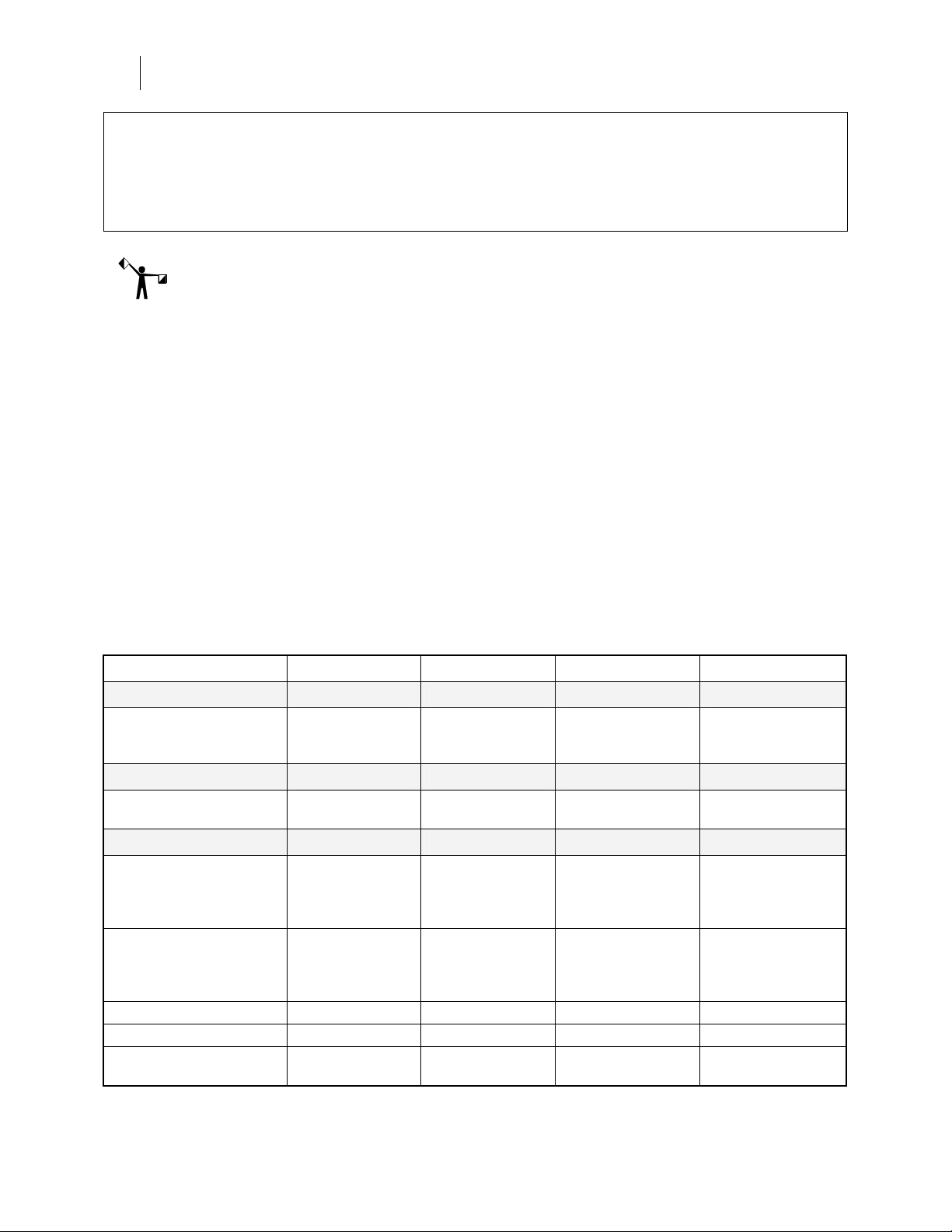
Windows XP 32 Windows XP 64 Windows Vista 32 Windows Vista 64 Design
Composer and other
design functions. Create
and save PLT files.
Rendering
GSPPlot rendering of SPL
files.
Output
EDGE via parallel cable
off-the-shelf
or
USB-to-Parallel cable
EDGE 2 via parallel cable
or
GSP custom USB-to-
Parallel cable
EDGE FX (Ethernet only) OK OK OK OK
Plotters via serial port OK OK OK OK
Plotters via Radio Shack®
26-183 USB to Serial Cable
OK OK OK OK
OK OK OK OK
OK OK OK NO. Use a separate
Plot Station on a
OK OK OK NO. Use a separate
OK Not Tested Not Tested Not Tested
system NOT using
Vista 64-bit.
Plot Station on a
system NOT using
Vista 64-bit.
Page 15

9
Chapter Two: Installing OMEGA Software
This section describes the step by step instructions that ARE REQUIRED to successfully
install OMEGA 2.6. When you install OMEGA 2.6 software, you MUST use a CD-ROM
drive for installation, your computer MUST be running Windows 2000, XP, or Vista. You
must be logged on as an Administrator and you MUST have an available USB port. The
installation steps are divided into three types of users:
New OMEGA users and GRAPHIX ADVANTAGE upgrades on page 11
OMEGA 2.0 – OMEGA 2.1 upgrades on page 17
OMEGA 1.5x upgrades on page 23
Installation steps
Understanding security issues
Installing the OMEGA 2.6 software
Restart the computer to ensure communication with the GERBER EDGE 2
Configuring the ports after OMEGA 2.6 installation
Understanding security issues
All new or upgraded OMEGA 2.6 systems require an OMEGA 2.6 USB security key connected
to the system for the software to run. The exceptions are OMEGA 2.5 and 2.5.1 USB security
keys which will allow the installation of OMEGA 2.6 without a password.
For newly purchased OMEGA CP, CS, LS, OMEGA PS with ART Path, a new
serialized OMEGA 2.6 USB security key is provided in your software kit.
For GRAPHIX ADVANTAGE upgrades, a new serialized OMEGA 2.6 USB security
key is provided in your software upgrade kit.
For OMEGA 2.0/2.1 to OMEGA 2.6 upgrades, an upgrade password is provided. The
installation process will upgrade your existing 2.0/2.1 security key to 2.6
For OMEGA 1.5x to OMEGA 2.6 upgrades, an upgrade OMEGA 2.6 USB security key
is provided in your software upgrade kit, along with an upgrade password. The
upgrade key will use the same serial number as your original 1.5x security key.
Note: OMEGA 2.6 requires the new OMEGA 2.6 USB security key even if you are already
using an OMEGA 1.5x USB security key.
Page 16

10
Getting Started
Installing OMEGA software
Understanding the Sentinel™ System Driver
The Sentinel System Driver allows your computer to find and work with your OMEGA 2.6
security key. The Sentinel System Driver version 7.3.2 will be automatically loaded during
OMEGA installation. If you are running an older version of the Sentinel System Driver, it will
be upgraded to version 7.3.2.
CAUTION: Only use the Sentinel System Driver version 7.3.2 that is installed from
the OMEGA 2.6 CD. Do not install the Sentinel System Driver from the SafeNet®
website.
Installing OMEGA 2.6 Software
Note: Preference settings from previous OMEGA installations are maintained if a new version
is loaded on top of a previous version without doing an uninstall first.
Follow one of these procedures to install OMEGA 2.6 software:
New OMEGA users and GRAPHIX ADVANTAGE upgrades on page 11
OMEGA 2.0 – OMEGA 2.1 upgrades on page 17
OMEGA 1.5X upgrades on page 23
Page 17

11
Installing OMEGA 2.6 software for New Users and GRAPHIX ADVANTAGE upgrades
Installation Process:
Connect the OMEGA 2.6 USB security key.
Install OMEGA 2.6 software.
Restart the computer to ensure communication with the GERBER EDGE 2.
Configure the Sentinel System Driver.
Install Fonts and Device Profiles.
Note: If your keyboard accelerators are hidden, do one of the following procedures to display
them. The procedures assume that Control Panel is in Category View rather than Classic View.
Windows 2000 - Click Start > Settings > Control Panel > Display > Effects. Turn off the check
box Hide keyboard navigation indicators until I use the Alt key.
Windows XP - Click Start > Control Panel > Appearance > Effects button. Turn off the check
box Hide underlined letters for keyboard navigation until I press the Alt key.
Windows Vista – Start > Control Panel > Ease of Access Center > Make the keyboard easier to
use > Make it easier to use keyboard shortcuts and access keys. Turn on the check box for
Underline keyboard shortcuts and access keys.
To install OMEGA 2.6 software, (which is provided on a CD); use a CD-ROM drive for the
installation on a computer which is running Windows 2000, XP, or Vista. You must be logged
on as an Administrator to install software. Your kit contains the OMEGA 2.6 installation CD.
Although screen prompts guide you through the installation, we recommend reviewing the
installation process in the next few pages prior to installation. You may also wish to review
information in:
Chapter Three: Adding Output Devices – if you have a Gerber Sabre™ router and
you need to update the firmware.
Chapter Six: HPGL Plotter Installation - if you are using a plotter which is not
listed in the install screen. (Many different plotters are referred to as HPGL plotters
because they use the HPGL standard command set to communicate. See page 80.)
Chapter Seven: Networking Devices - if you are using printers over a network.
Page 18
12
Getting Started
Installing OMEGA software
Installing OMEGA 2.6 software
WARNING: Do not exit or cancel the OMEGA 2.6 installation procedure once it has
begun. Exiting the installation process before completion will damage your security
key.
Note: Preference settings from previous OMEGA installations are maintained if a new version
is loaded on top of a previous version without doing an uninstall first.
To begin OMEGA 2.6 installation
Note: The security key must be connected at all times for OMEGA 2.6 to run properly. If you
need assistance with your system or to locate the USB security key, contact Gerber Technical
Support at 860-644-6971.
1 Close any Windows or applications that are running including any virus scan
software. The screen displays the Windows desktop.
2 Locate the OMEGA 2.6 USB security key. (It ships in a small, pink
anti-static bag in your OMEGA kit.)
3 Plug the OMEGA 2.6 security key into any USB port or hub.
4 The Windows Found New hardware wizard should prompt you. Click OK. The USB
drivers will automatically be found.
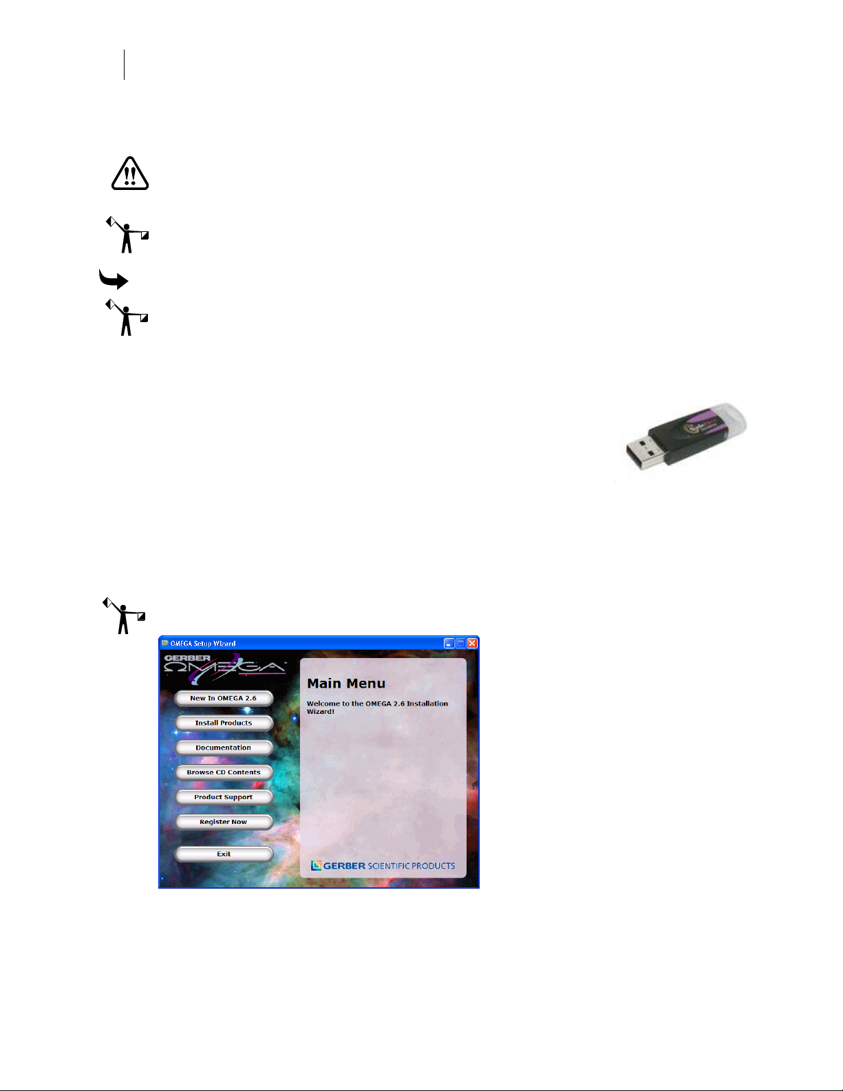
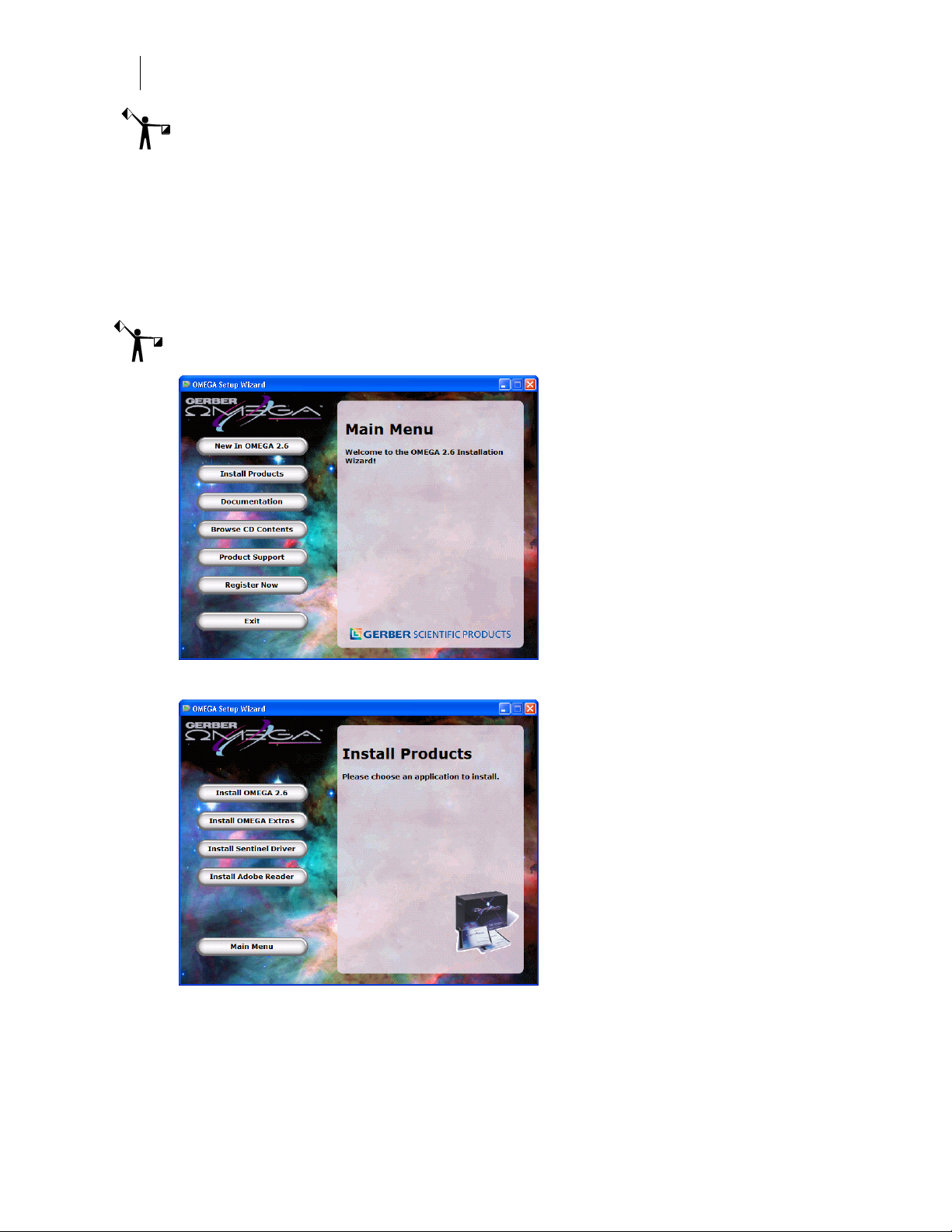
5 Insert the OMEGA 2.6 CD into the CD-ROM drive. (If the OMEGA Setup Wizard does
not start by itself, click Start > Run. Browse the CD for Setup.exe. Select Setup.exe and
then click OK to open the OMEGA 2.6 Setup Wizard.)
Note: The OMEGA 2.6 Setup Wizard has buttons for other procedures and documentation.
6 Choose Install Products. An Install Products screen opens.
Page 19

13
7 Choose Install OMEGA 2.6. The Choose Setup Language dialog box opens. Verify the
correct language is selected.
8 Click Next. The Welcome to Install Shield Wizard dialog box opens.
9 Click Next. The License Agreement dialog box opens. If you agree to the License
Agreement terms, Click Yes. If not, click No and return the complete OMEGA kit to
your distributor.
10 The Customer Information dialog box opens. Enter your name and your company
name. The serial number will automatically register from your security key. Click
Next.
11 The Choose Destination Location dialog box opens. Use the browse button to navigate
the folders to find the location where you want OMEGA 2.6 to be installed.
Note: By default, Setup will install OMEGA in the C:\GSP directory (for new installation) or
the C:\WINDOWS\GSP directory (for some upgrades). Fonts, Libraries, and Software have
their own folders within the GSP directory. Palettes and Manuals are folders within the
GSP\Software folder.
12 Click Next.
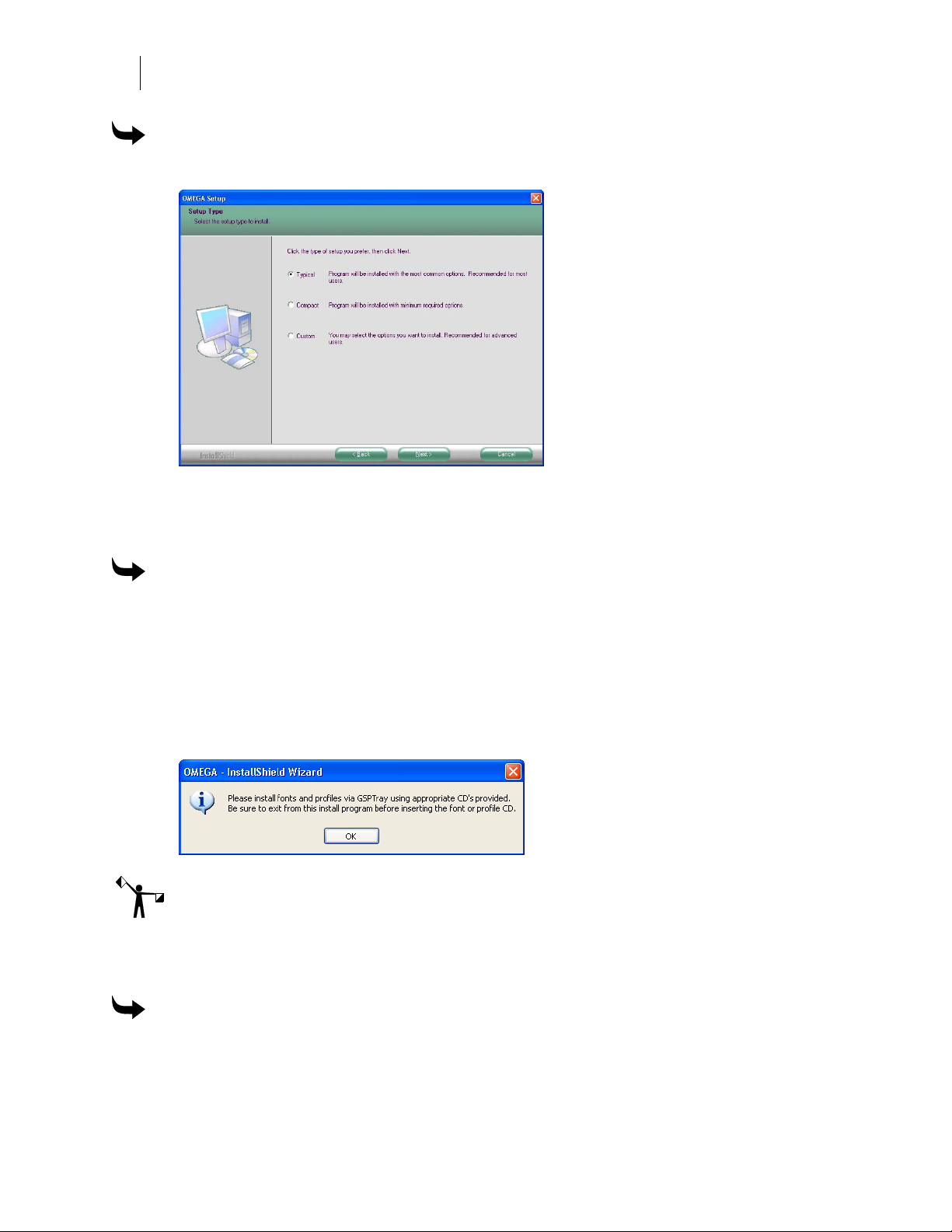
Choosing the setup type
The Setup Type dialog box opens. You may choose from the three setup types described below.
Read the explanation for each setup type. Most users should select Typical.
Typical installs all the most common software. Unless you are installing an extra
option or have limited disk space, you should select Typical.
Compact installs the minimum required software options. A Compact installation
does not include online Help files, samples, or on-line manuals. Select Compact only if
you need to conserve hard disk space, such as on a laptop.
Custom lets you specify the options you want to install. Select Custom if you are
adding an option to your system. The setup program will ask you for a password for
each option with the exception of ART Path which does not require a password.
Options can be added at this time, or at a later date.
Page 20

14
Getting Started
Installing OMEGA software
If you wish to purchase an option, call your Gerber distributor. You will receive
the password when you purchase that option. If you think you have purchased the
option and have not received your password, you will need to find your original
disk or proof of purchase, and then contact Gerber Technical Support at
860-644-6971.
To choose the Setup type
1 Choose the setup type you desire: Typical, Compact, or Custom.
2 Click Next.
3 Go to the procedure for the installation type that you selected: Typical and Compact
installations or Custom installation.
To complete Typical and Compact installations
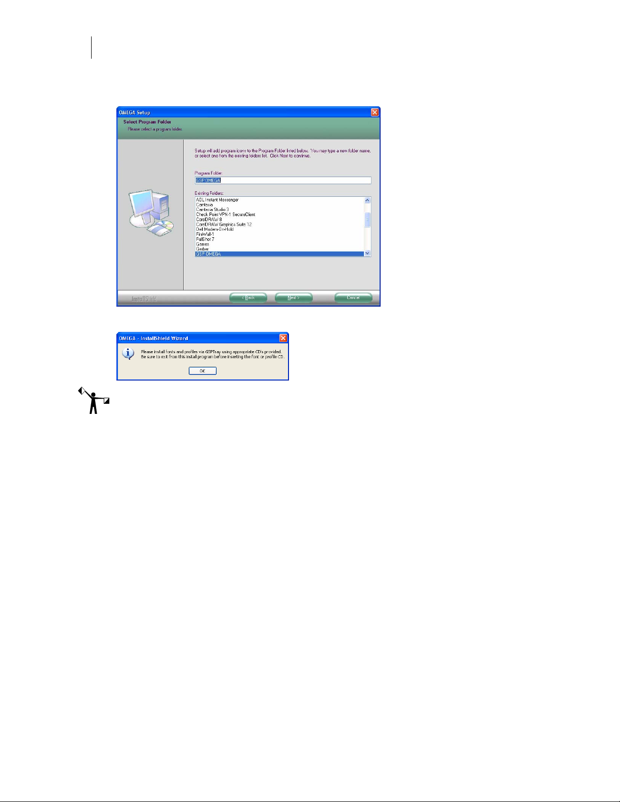
1 In the Select Program Folder dialog box, follow the on-screen instructions. OMEGA 2.6
will begin to install.
2 As the processing box displays, an informational OMEGA slide presentation will play.
3 Follow the on-screen instructions in the dialog boxes that appear.
4 Once the installation is finished, a font and profile information dialog box opens.
Note: Fonts and profiles must be loaded using the appropriate CD and GSPTray. For more font
information refer to the section “Installing fonts from the OMEGA Font CD,” on page 61. For
more Profile information refer to “Using the Gerber Profile Manager” on page 64.
Page 21
15
5 Please reboot your computer even if you are not prompted to do so. Restarting your
computer ensures communications with the GERBER EDGE 2.
6 Click OK. Proceed to “Configuring the ports after OMEGA 2.6 installation” on page
31.
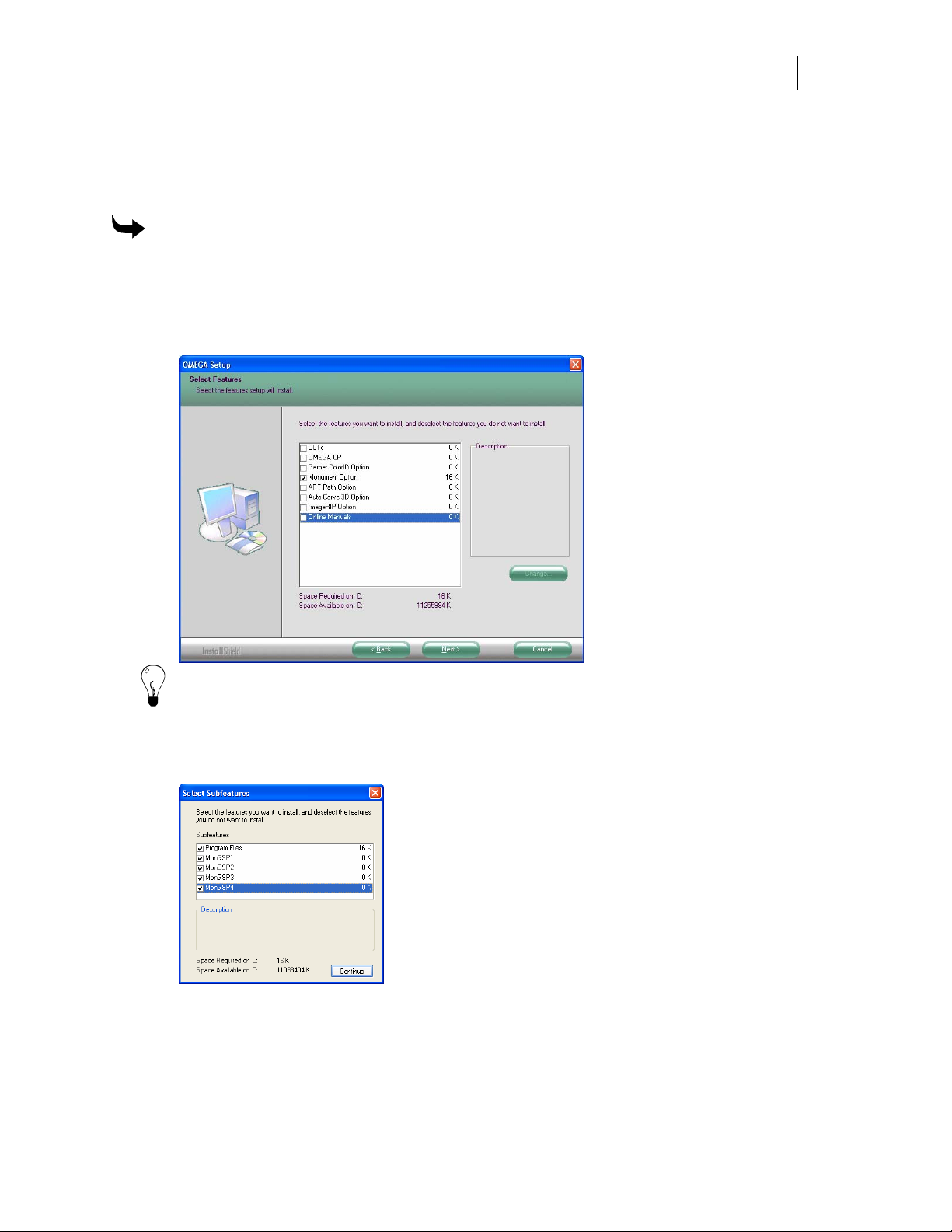
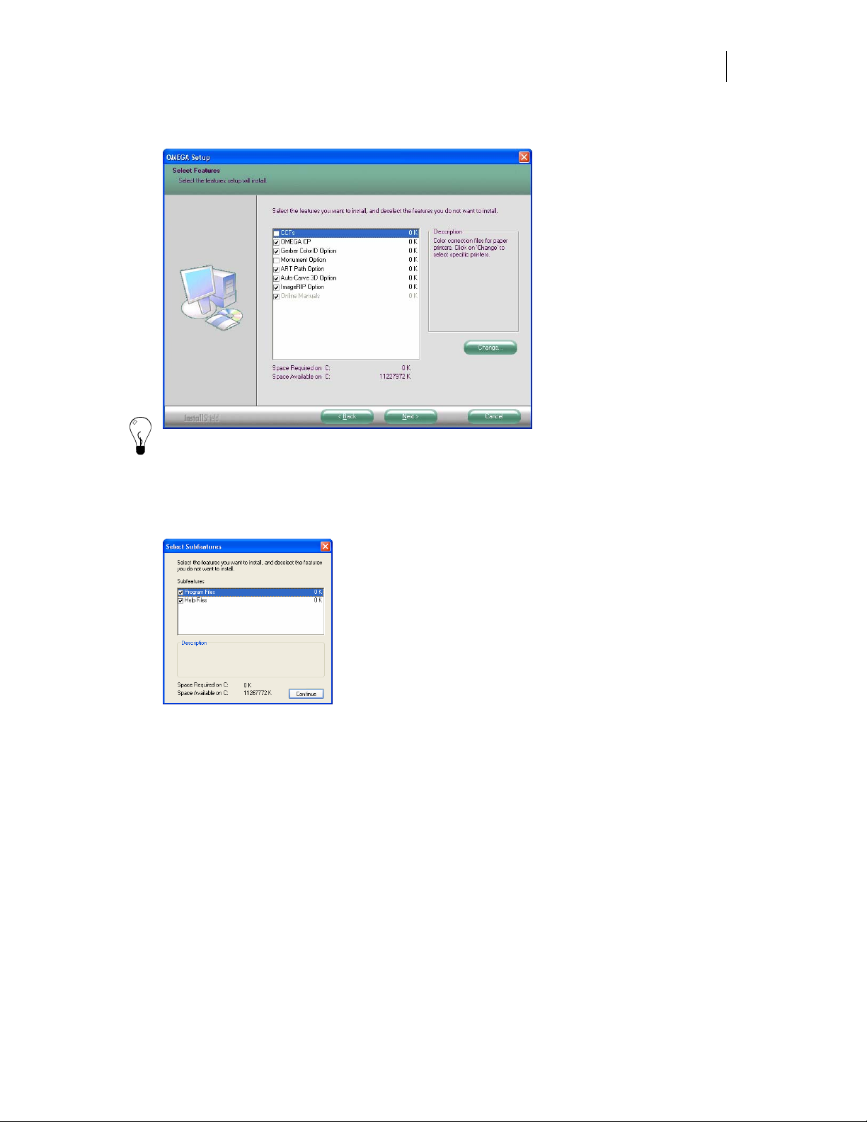
To complete a Custom Installation
1 Choose Custom as the setup type from the Setup Type dialog box. The Select Features
dialog box opens.
2 Choose the components you want to install. A check mark appears next to those
programs. The space required for each component is shown.
Tip: To deselect a program with a check mark, click the checkbox. The check mark disappears.
3 Click the Change button in the Select Features dialog box to open the Select Sub-
components dialog box. If a component does not have sub-components, the Change
button is disabled.
4 Choose the sub-components to load and click Continue in the Select Sub-components
dialog box to continue with the installation. The Select Components dialog box
reopens.
5 Follow the on-screen instructions in the Select Components dialog box. Click Next.
Page 22
16
Getting Started
Installing OMEGA software
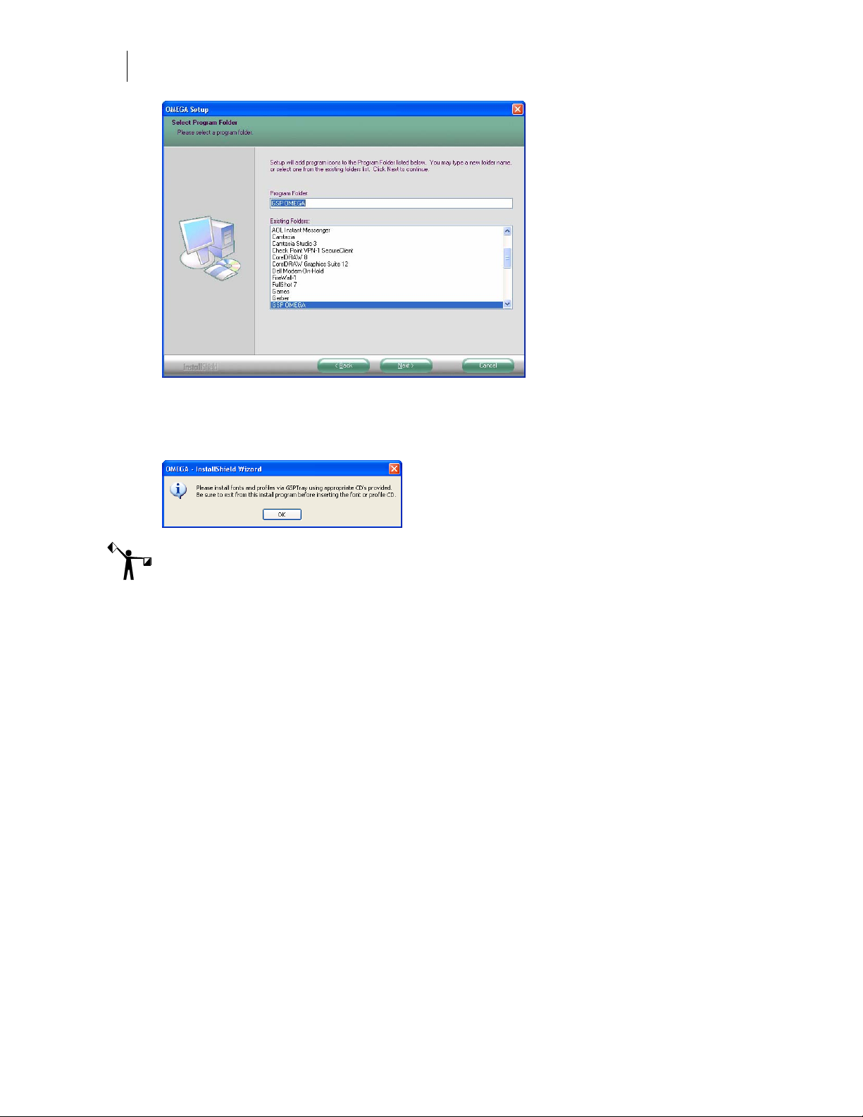
6 The Select Program Folder dialog box opens. Follow the on-screen instructions. Click
Next. OMEGA 2.6 will begin to install.
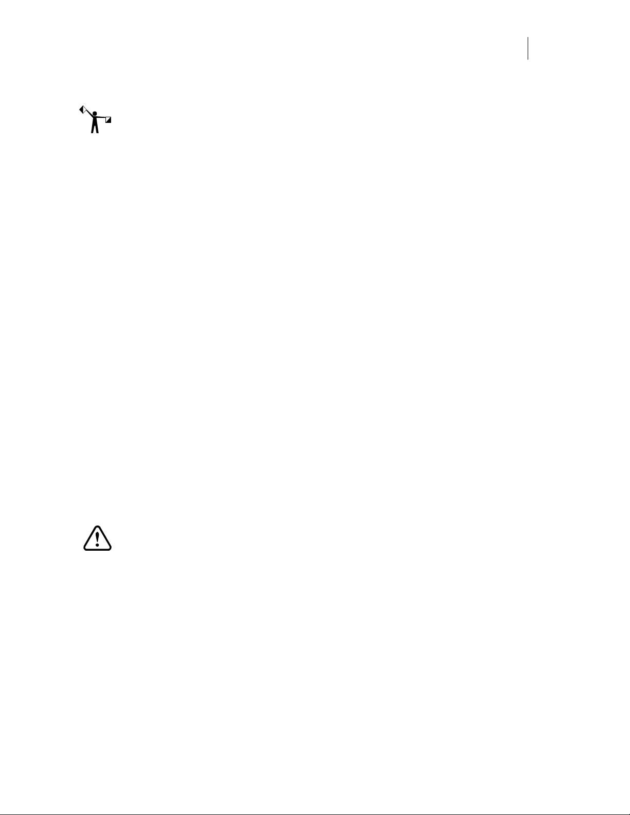
7 Once the installation is finished, the font and profile information dialog box opens.
Note: Fonts and profiles must be loaded using the appropriate CD and GSPTray. For more font
information refer to the section “Installing fonts from the OMEGA font CD,” on page 61. For
more Profile information refer to “Using the Gerber Profile Manager” on page 64.
8 Please reboot your computer even if you are not prompted to do so. Restarting your
computer ensures communications with the GERBER EDGE 2.
Page 23

17
Installing OMEGA 2.6 software for OMEGA 2.0 - 2.1 Users
Installation Process:
Install OMEGA 2.6 software.
Restart the computer to ensure communication with the GERBER EDGE 2.
Configure the Sentinel System Driver.
Install Fonts and Profiles.
Note: If your keyboard accelerators are hidden, do one of the following procedures to display
them. The procedures assume that Control Panel is in Category View rather than Classic View.
Windows 2000 - Click Start > Settings > Control Panel > Display > Effects. Turn off the check
box Hide keyboard navigation indicators until I use the Alt key.
Windows XP - Click Start > Control Panel > Appearance > Effects button. Turn off the check
box Hide underlined letters for keyboard navigation until I press the Alt key.
Windows Vista – Start > Control Panel > Ease of Access Center > Make the keyboard easier to
use > Make it easier to use keyboard shortcuts and access keys. Turn on the check box for
Underline keyboard shortcuts and access keys.
When you install OMEGA 2.6 software (the software is provided on a CD), use a CD-ROM
drive for the installation and your computer must be running Windows 2000, XP, or Vista. You
must be logged on as an Administrator to install software. Your kit contains the OMEGA 2.6
installation CD, for information on the kit contents go to page 3.
Although screen prompts guide you through the installation, we recommend reviewing the
installation process in the next few pages prior to installation. You may also wish to review
information in:
Chapter Three: Adding Output Devices – if you have a Gerber Sabre router and
you need to update the firmware.
Chapter Six: HPGL Plotter Installation - if you are using a plotter which is not
listed in the install screen. (Many different plotters are referred to as HPGL plotters
because they use the HPGL standard command set to communicate. See the list on
page 80.)
Chapter Seven: Networking Devices - if you are using printers over a network.
To begin OMEGA 2.6 installation
WARNING: Do not exit or cancel the OMEGA 2.6 installation procedure once it has
begun. Exiting the installation process before completion will damage your security
key.
Note: You can find the password in the sealed envelope included in the OMEGA upgrade kit.
Should the password be lost or invalid, contact Gerber Technical Support at 860-644-6971.
Please have your OMEGA 2.0 - 2.1 serial number, GSPSystem ID number and sales order
numbers available. Refer to “Locating the System ID and Serial Number” on page 72.
Page 24
18
Getting Started
Installing OMEGA software
Note: Preference settings from previous OMEGA installations are maintained if a new version
is loaded on top of a previous version without doing an uninstall first.
1 Verify that the OMEGA 2.0/2.1 USB security key has been installed correctly. Your
existing security key will be updated during the upgrade process.
2 Close any Windows or applications that are running including GSPTray and virus
scan software. The screen displays the Windows desktop.
3 Insert the OMEGA 2.6 CD into the CD-ROM drive. If the OMEGA Setup Wizard
doesn’t start by itself, click Start > Run. Browse the CD for Setup.exe. Click Setup.exe.
Click OK to open the OMEGA 2.6 Setup Wizard.
Note: The OMEGA 2.6 Setup Wizard has buttons for other procedures and documentation.
4 Choose Install Products. An Install Products screen opens.
5 Choose Install OMEGA 2.6. The Choose Setup Language dialog box opens.
6 Click Next. The Welcome dialog box opens.
7 Click Next. The OMEGA 2.6 Upgrade dialog box opens. Enter your upgrade password
(provided with the OMEGA upgrade kit).
Page 25
19
8 Click Next. The License Agreement dialog box opens. Click Yes. If you agree to the
License Agreement terms, click Yes. If not, click No and return the complete OMEGA
kit to your distributor.
9 The Customer Information dialog box opens. Enter your name and your company
name. The serial number will automatically register from your security key. Click
Next.
Note: By default, Setup will install OMEGA in the C:\GSP directory (for new installation) or
the c:\WINDOWS\GSP directory (for some upgrades). Fonts, Libraries, and Software have
their own folders within the GSP directory. Palettes and Manuals are folders within the
GSP\Software folder.
Choosing the setup type
The Setup Type dialog box opens. You may choose from the three setup types described below.
Read the explanation for each setup type. Most users should select Typical.
Typical installs all the most common software. Unless you are installing an extra
option or have limited disk space, you should select Typical.
Compact installs the minimum required software options. A Compact installation
does not include Help files, samples, or on-line manuals. Select Compact only if you
need to conserve hard disk space, such as on a laptop.
Custom lets you specify the options you want to install. Select Custom if you are
adding an option to your system. The setup program will ask you for a password
for each option with the exception of ART Path which does not require a password.
Options can be added at this time, or at a later date.
If you wish to purchase an option, call your Gerber distributor. You will receive the
password when you purchase that option. If you think you have purchased the option
and have not received your password, you will need to find your original disk or
proof of purchase, and then contact Gerber Technical Support at 860-644-6971.
Page 26
20
Getting Started
Installing OMEGA software
To choose the Setup type
1 Choose the setup type you desire: Typical, Compact, or Custom.
2 Click Next.
3 Go to the procedure for the installation type that you selected: Typical and Compact
installations or Custom installation.
To complete Typical and Compact installations
1 In the Select Program Folder dialog box, follow the on-screen instructions. OMEGA 2.6
will begin to install.
2 As the processing box displays, an informational OMEGA slide presentation will play.
3 Follow the on-screen instructions in the dialog boxes that appear.
4 Once the installation is finished, the font and profile information dialog box opens.
Click OK.
Note: Fonts and profiles must be loaded using the appropriate CD and GSPTray. For more font
information refer to the section “Installing fonts from the OMEGA Font CD”, on page 61. For
more Profile information refer to “Using the Gerber Profile Manager” on page 63.
5 Please reboot your computer even if you are not prompted to do so. Restarting your
computer ensures communications with the GERBER EDGE 2.
To complete a Custom Installation
1 Choose Custom as the setup type from the Setup Type dialog box. The Select Features
dialog box opens.
Page 27
21
2 Choose the components you want to install. A check mark appears next to those
programs. The space required for each component is shown.
Tip: To deselect a program with a check mark, click the checkbox. The check mark disappears.
3 Click the Change button in the Select Components dialog box to open the Select Sub-
components dialog box. If a component does not have sub-components, the Change
button is disabled.
4 Choose the sub-components to load and click Continue in the Select Sub-components
dialog box to continue with the installation. The Select Features dialog box reopens.
5 Follow the on-screen instructions in the Select Features dialog box. Click Next.
6 The Select Program Folder dialog box opens. Follow the instructions. Click Next.
Page 28
22
Getting Started
Installing OMEGA software
7 OMEGA 2.6 will begin to install. As the processing box displays, an informational
OMEGA slide presentation will play.
8 Once the installation is finished, the font and profile information dialog box opens.
Note: Fonts and profiles musts be loaded using the appropriate CD and GSPTray. For more
font information refer to the section “Installing fonts from the OMEGA Font CD”, on page 61.
For more Profile information refer to “Using the Gerber Profile Manager” on page 64.
9 Reboot your computer even if you are not prompted to do so. Restarting your
computer ensures communications with the GERBER EDGE 2.
Page 29
23
Installing OMEGA 2.6 software for OMEGA 1.5x users
Note: There are two types of OMEGA 1.5x upgrades:
A factory-configured OMEGA 1.5x to 2.6 upgrade with a new 2.6 USB security key and a new
serial number.
An OMEGA 1.5x to 2.6 upgrade in which the original 1.5x security key will be converted
during OMEGA 2.6 installation using the Copy-to-USB procedure.
This procedure describes the OMEGA 1.5x upgrade in which the existing security key will be
converted using the Copy-to-USB procedure during the OMEGA 2.6 installation. If you have a
new serialized USB security key, following the procedure “Installing OMEGA 2.6 software for
New Users or GRAPHIX ADVANTAGE upgrades” on page 11.
Installation Process:
Install OMEGA 2.6 software.
Restart the computer to ensure communication with the GERBER EDGE 2.
Configure the Sentinel System Driver.
Install Fonts and Profiles.
OMEGA 1.5x users upgrading to OMEGA 2.6 receive a new upgrade OMEGA 2.6 USB security
key in the upgrade kit. It is important to tag the security keys before beginning the procedure to
make it easier to identify which key is the original and which key is the upgrade OMEGA 2.6
USB security key.
Using a permanent marker record the Gerber serial number from your original security key
onto the upgrade USB key (refer to “Locating the System ID and Serial Number” on page 72).
The serial number is important to have when ordering options for your OMEGA system, as well
as when seeking assistance from GSP Technical Support.
Understanding the Sentinel System Driver
CAUTION: Only use the Sentinel System Driver version 7.3.2 that is installed from
the OMEGA CD. Do not install a Sentinel System Driver from the SafeNet®
website.
The Sentinel System Driver allows your computer to find and work with your OMEGA 2.6
security key. The existing Sentinel System Driver will be automatically updated to version 7.3.2
during OMEGA 2.6 installation. After installing OMEGA 2.6 you will configure the Sentinel
System Driver to prevent communication errors to devices installed on other ports.
Understanding security key conversion
The upgrade OMEGA 2.6 USB security key must be activated by transferring the information
from the existing OMEGA 1.5x security key to the upgrade OMEGA 2.6 USB security key.
Follow one of the procedures described in this section.
Page 30

24
Getting Started
Installing OMEGA software
The first procedure describes a system that has either:
An existing OMEGA 1.5x parallel security key and an available USB port.
An existing OMEGA 1.5x USB security key and two USB ports (one for the existing
USB key and one available for the upgrade OMEGA 2.6 USB key).
The second procedure describes a system that has:
An existing OMEGA 1.5x USB security key installed in the only available USB port.
Installing OMEGA 2.6 software
WARNING: Do not exit or cancel the OMEGA 2.6 installation once it has begun.
Exiting the installation process before completion will damage your security keys.
Note: Preference settings from previous OMEGA installations are maintained if a new version
is loaded on top of a previous version without doing an uninstall first.
To install OMEGA 2.6 on a system with a parallel and a USB port (for a
parallel OMEGA 1.5x key), or on a system with two USB ports (for a USB
OMEGA 1.5x key)
1 Close any Windows applications that are running including GSPTray and any virus
scan software. You must be logged on as an Administrator to install software.
2 Confirm that your OMEGA 1.5x USB or parallel security key is in its original USB or
parallel port.
3 Install the new OMEGA 2.6 USB upgrade security key in an available USB port. The
Windows Found New Hardware wizard installs the USB device driver automatically.
Note: If your system has only one USB port and you currently have the OMEGA 1.5x USB
security key installed in it, go the following procedure “To install a new OMEGA 2.6 USB
security key on a system with only one USB port.”
4 Insert the OMEGA 2.6 CD into the CD-ROM drive. If the OMEGA Setup Wizard does
not start by itself, click Start > Run. Browse the CD for Setup.exe. Click Setup.exe and
then click OK to open the OMEGA 2.6 Setup Wizard.
Page 31

25
5 Click Install Products. An Install Products screen opens.
6 Choose Install OMEGA 2.6. The Choose Setup Language dialog box opens. Verify the
correct language is selected.
7 A message about the Sentinel Driver being upgraded displays.
8 Click OK. The Welcome dialog box opens. Click Next.
9 The Gerber Copy to USB Security Key dialog box opens. Follow the instructions in the
dialog box. The original OMEGA 1.5x security key should be installed in the usual
parallel or USB port and the new OMEGA 2.6 USB security key should be installed in
an available USB port. Click Next in the Gerber Copy to USB Security Key dialog box.
OMEGA 2.6 security key
Page 32

26
Getting Started
Installing OMEGA software
Note: If you system has only one USB port and you currently have the OMEGA 1.5x USB
security key installed in it, go to the following procedure: “To install a new OMEGA 2.6 USB
security key on a system with only one USB port.”
10 The Gerber Copy to USB Security Key – Password dialog box opens. Enter the
upgrade password in the box. The password is provided in your OMEGA 2.6 upgrade
kit in a sealed envelope. Click Next.
11 The next Gerber Copy to USB Security Key dialog box displays with different
instructions. Follow the instructions in the dialog box. Users residing in the USA
should send the original parallel security key back to Gerber in the postage paid,
pre-addressed envelope provided. Refer to the instructions on the envelope for more
information. Users outside of the USA should return the original parallel security key
to the distributor. Click Next.
Note: If you have not already done so, using a permanent marker record the Gerber serial
number from your original security key onto the new USB key. The serial number is important
to have when ordering options for your OMEGA system, as well as when seeking assistance
from GSP Technical Support.
12 Remove your original parallel or USB security key and return it to GSP in the provided
envelope or give it to your distributor. Click Exit.
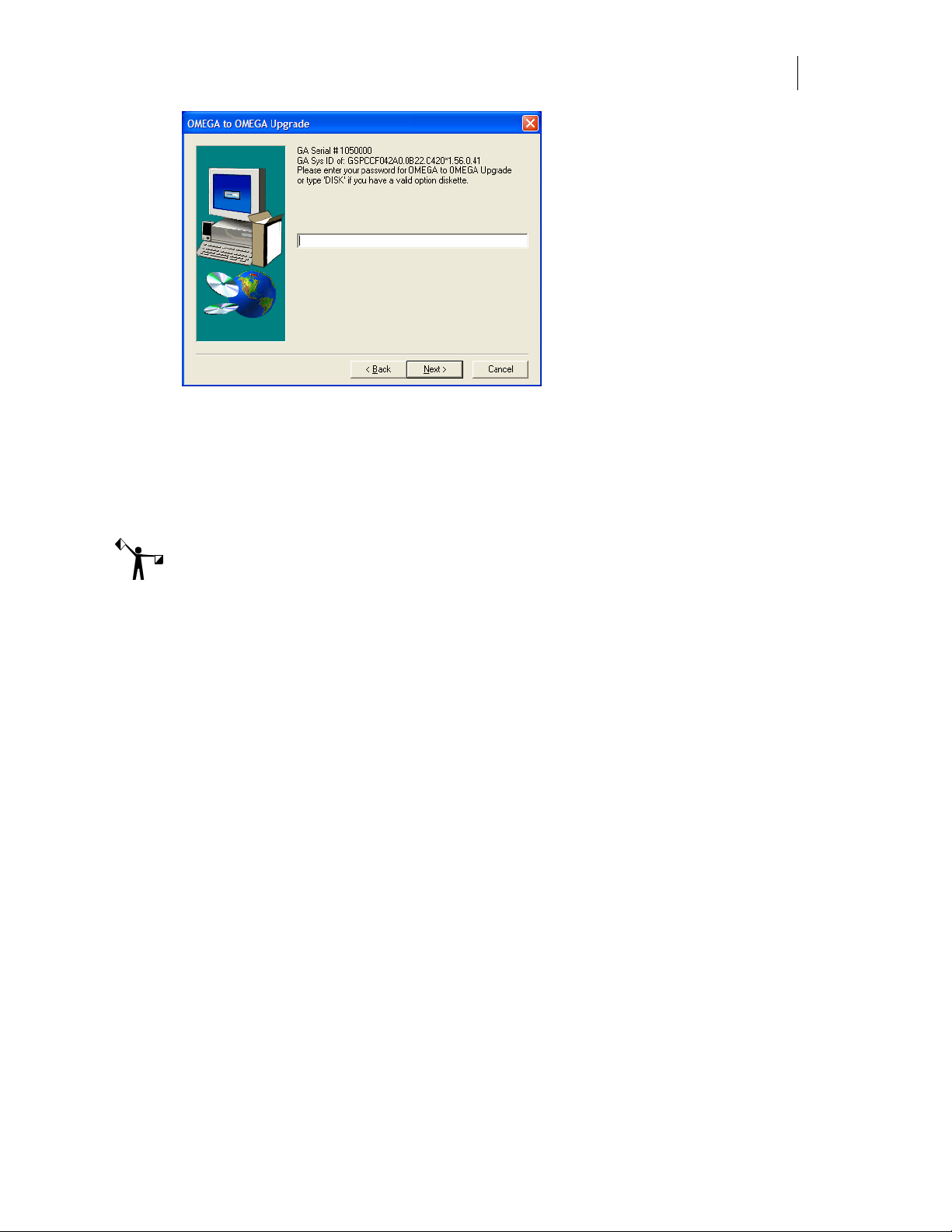
13 The OMEGA to OMEGA upgrade dialog box opens requesting your password. Enter
the password from step 10. Click Next.
Page 33

27
14 Proceed to step #9 (Software License Agreement) in “Installing OMEGA 2.6 software
for New Users and GRAPHIX ADVANTAGE Users” on page 13.
To install a new OMEGA 2.6 USB security key on a system with only one USB
port
WARNING: Do not exit or cancel the OMEGA 2.6 installation procedure once it has
begun. Exiting the installation process before completion will damage your security
keys.
1 Close any Windows applications that are running including GSPTray and any virus
scan software.
2 Insert your current OMEGA 1.5x USB security key in the USB port.
3 Insert the OMEGA 2.6 CD into the CD-ROM drive. If the OMEGA Setup Wizard does
not start by itself, click Start > Run. Browse the CD for Setup.exe. Click Setup.exe.
Click OK to open the OMEGA 2.6 Setup Wizard.
4 Click Install Products. An Install Products screen opens.
Page 34

28
Getting Started
Installing OMEGA software
5 Choose Install OMEGA 2.6. The Choose Setup Language dialog box opens. Verify the
correct language is selected.
6 A message about the Sentinel Driver being upgraded displays.
7 Click OK. The Welcome dialog box opens. Click Next.
8 The Gerber Copy to USB Security Key dialog box opens. Follow the instructions in the
dialog box. (Only the original 1.5x security key should be installed.) Click Next.
9 The Gerber Copy to USB Security Key – Password dialog box opens. Enter the
upgrade password in the box. The password is provided in your OMEGA 2.6 upgrade
kit in a sealed envelope. Click Next.
OMEGA 2.6 security key
10 Remove your original security key and install your new upgrade OMEGA 2.6 USB
security key per the instructions in the dialog box. Click OK.
Page 35

29
11 Continue to follow the instructions in the dialog box. Remove the new upgrade
OMEGA 2.6 USB security key and reinstall the original OMEGA 1.5x USB security key.
Click OK.
12 Remove the original OMEGA 1.5x USB security key and install the new OMEGA 2.6
USB security key in its place.
13 Your USB security key has been copied. Follow the instructions. Please return the
OMEGA 1.5x security key to GSP in the provided envelope or give it to your
distributor. Click OK.
Note: If you have not already done so, using a permanent marker record the Gerber serial
number from your original security key onto the new USB key. The serial number is important
to have when ordering options for your OMEGA system, as well as when seeking assistance
from GSP Technical Support.
14 Leave the OMEGA 2.6 security key in place and click Exit.
15 The OMEGA to OMEGA Upgrade dialog box opens requesting your password. Enter
the password from step 9. Click Next.
Page 36

30
Getting Started
Installing OMEGA software
16 Proceed to step #9 (Software License Agreement) in “Installing OMEGA 2.6 software
for New Users and GRAPHIX ADVANTAGE Users” on page 13.
Page 37

31
Configuring the ports after OMEGA 2.6 installation
After installing the OMEGA 2.6 software it is important to instruct your computer on where to
find the USB security key. By doing this the security software will not interfere with other
devices on other ports. Parallel ports should be turned off as described in the following
procedure.
Note: To run a GERBER EDGE 2 the Port Type must be an ECP port or the EDGE 2 will not
function properly.
To determine port configuration
1 Click Start > Programs > GSP OMEGA > Sentinel Config to open the Sentinel System
Driver Configuration Utility.
2 Click Configure Driver to open the Sentinel Driver Port dialog box.
3 Configure all parallel ports (non-USB) to say No in the Use? Section. All USB ports
should say Yes.
4 Use the Edit button to go to the Configure Port dialog box and change the Use this
port? To Yes or No. (No for parallel ports, yes for USB ports)
Note: If your system has a third party port, you may need to manually configure the address
using the Add button.
5 Click OK to return to the Sentinel System Driver dialog box.
6 Click OK to restart the computer so the change will take effect. On some systems, you
may have to restart manually.
Tip: If you do not already have output devices installed, it is advisable to install them now. See
“Chapter Three: Adding Output Devices” for more information.
Page 38

32
Getting Started
Installing OMEGA software
Activating Arabic language support
Arabic language support is available for OMEGA 2.6 or higher on Windows XP, Windows 2000,
or Windows Vista. Enabling Arabic for OMEGA requires the following steps:
Enable Arabic support in Windows XP, 2000, or Vista.
Enable Arabic fonts in Composer on the Tools > Options > Text tab.
Install the Arabic Font Pack using Font Manager or transfer existing Arabic fonts from
GRAPHIX ADVANTAGE.
After enabling Arabic support for OMEGA, Arabic fonts may be entered using the Enter/Edit
Text dialog box or the Enter/Edit Small Text dialog box. Arabic fonts cannot be entered using
Text on the Work Surface (TOWS).
For complete instructions on how to enable Arabic and load the Arabic fonts, see “Installing
Arabic for OMEGA 2.5.1 or higher.pdf” located in the Documentation folder on the OMEGA
Installation CD or see OMEGA Help.
Page 39

33
Chapter Three: Adding Output Devices
Whether installing OMEGA 2.6 for the first time or upgrading your software, you may need to
add output devices. The Add or Delete Plotters/Routers, Add or Delete Vinyl Printers, or Add
or Delete ImageRIP Printers dialog boxes enable you to install the output devices. You can
access these dialog boxes three different ways:
1 During installation of OMEGA 2.6 by turning on the Install Printers/Plotters checkbox
located on the final installation screen.
2 By clicking right on the GSPTray icon that is found at the bottom right of your
Windows status bar and choosing Install Vinyl Printer, Install Plotter/Router, or
Install ImageRIP Printer.
3 By clicking Start > Programs > GSP OMEGA > GQMgr > Install menu > Plotter, Vinyl
Printer, or Ink Jet Printer.
These procedures are described in the following pages:
To add output devices after installing OMEGA 2.6 software
To add or delete a local vinyl printer (parallel and USB-to-Parallel)
To add or delete a remote vinyl printer
To add or delete a network vinyl printer
To add or delete a local inkjet printer
To add or delete a remote inkjet printer
To add a local plotter via a COM port
To install a plotter via a USB port
To delete a local plotter
To add or delete a remote plotter
Adding output devices after OMEGA installation
To add output devices after installing OMEGA software
1 Turn on Install Plotters/Printers checkbox in the OMEGA Setup Complete dialog box
to open the Add or Delete Gerber Vinyl Printer(s) dialog box.
2 If you are installing a vinyl printer use one of the procedures in “Installing vinyl
printers.” If you are not adding a vinyl printer, click Close to display the next device
installation dialog box – either Add or Delete ImageRIP Printer(s) dialog box (if
Page 40

34
Getting Started
Adding Output Devices
ImageRIP is installed) or the Add or Delete Plotter/Router(s) dialog box. Follow the
installation procedures later in this chapter.
3 If you are not adding an inkjet printer, click Close to display the Add or Delete
Plotter/Router(s) dialog box. Follow the installation procedures later in this chapter.
Installing vinyl printers
OMEGA allows you to install three types of vinyl printers:
Local (Parallel or USB-to-Parallel)
Remote
Network (Gerber MAXX 2 or GERBER EDGE FX)
Local vinyl printers
GERBER EDGE and EDGE 2 vinyl printers can be connected to the OMEGA computer via a
parallel cable or USB-to-Parallel cable.
At this time, Windows Vista 64-bit does not support OMEGA parallel port usage. Therefore
you cannot communicate with a GERBER EDGE or EDGE 2 printer via a parallel port when
using Windows Vista 64-bit. Gerber recommends that you use Vista 32-bit or upgrade to a
GERBER EDGE FX which communicates via an Ethernet cable. Alternately, you can render on a
Vista 64-bit system and output to a GERBER EDGE or EDGE 2 using a separate OMEGA Plot
Station installed on a Windows XP or 2000 computer. See the compatibility chart on page 8 for
details.
Note the following restrictions for communicating with the GERBER EDGE or EDGE 2:
GERBER EDGE – parallel cable, generic USB-to-Parallel cable, or GERBER custom USB-
to-Parallel cable
GERBER EDGE 2 – parallel cable or GERBER custom USB-to-Parallel cable
Installing a local vinyl printer using a parallel cable
This section describes connecting the local vinyl printer using a parallel cable. See “Installing a
local vinyl printer via USB” for additional instructions on connecting using a USB-to-Parallel
cable.
To add a local vinyl printer via a parallel cable
1 Open the Add or Delete Gerber Vinyl Printer(s) dialog box using one of the methods
on page 33. The Local tab displays.
Page 41

35
2 Choose a printer from the Available Vinyl Printers on local system list.
3 Choose the Local Port.
4 Click Add to open the Add-Name Device dialog box.
5 Use the name provided or enter your own description and click OK. The name of the
new vinyl printer and the port will appear in the Installed Vinyl Printers field of the
Add or Delete Gerber Vinyl Printer(s) dialog box.
6 If you wish to modify which profiles display in OMEGA, click the Profile Manager
button to open the Gerber Device Profile Manager dialog box. Turn on which profiles
that you want to appear (EDGE, EDGE 2, EDGE FX, or MAXX 2) and uninstall any
profiles that are unnecessary and click OK.
Page 42

36
Getting Started
Adding Output Devices
7 Click Close to close the Add or Delete Gerber Vinyl Printer(s) dialog box.
Installing a GERBER EDGE using a generic USB-to-Parallel cable
You can install a GERBER EDGE as a USB device using a generic USB-to-Parallel available at
local computer stores. Most of these generic USB-to-Parallel cables use the standard Windows
drivers to communicate with the printer. The USB installation option is available with the
following software configurations:
OMEGA 2.5.1 or higher
OMEGA 2.5 with software updates to GQ Mgr (version 2,5,0,11 or higher) and G32
Setup.dll. These software updates are available from the download section of the GSP
web site: http://www.gspinc.com/support/downloads/software.html
Gerber has performed limited testing of USB-to-Parallel cable and cannot guarantee success
with all cables in the market. Your results may vary. During testing we have experienced
success with the following cables:
InSystem Design ISD 103
Belkin® VID_05AB (This older Belkin cable was successful; a newer Belkin cable
IVD_050D did not work.)
Radio Shack® VID1453
To connect the USB-to-Parallel cable and install the driver
Note: You must have Administrative privileges to install the Windows USB-to-Parallel driver
or any software updates on your system.
1 Be sure the GERBER EDGE is powered off. Connect the parallel (Centronics) end of
the cable into the back of the GERBER EDGE.
Page 43

37
2 Connect the USB end of the cable into the USB port of your computer. Windows
should detect the new device and display the "Found new hardware: USB Printing
Support" message on the Windows task bar.
3 Within several minutes the computer should automatically locate and install the driver
and then display the "Found new hardware: Your hardware is installed and ready to
use" message.
Installing the GERBER EDGE as a USB device
Installing the GERBER EDGE via USB is a multi-step process:
Install the GERBER EDGE as a USB device.
Assigning the Vendor and Product ID numbers to the USB-to-Parallel cable.
Note: This procedure assumes that you installed OMEGA 2.5.1 or higher. OMEGA 2.5
requires the USB-to-Parallel software update from the GSP website before installing the
GERBER EDGE as a USB device.
To install the GERBER EDGE as a USB printer
1 Open the Add or Delete Vinyl Printer(s) dialog box using one of the following
techniques:
Click Start > Programs > GSP OMEGA > GQ Mgr to open the GQ Manager dialog box.
Click Install and choose Vinyl Printer. The Local tab displays.
OR
Right-click the GSPTray icon that is found on the bottom right of your Windows task
bar and choose Install Vinyl Printer. The Local tab displays.
2 Choose a GERBER EDGE or GERBER EDGE 2 and click USB for the Local Port.
3 Click Add to open the Add - Name Device dialog box.
Page 44

38
Getting Started
Adding Output Devices
4 Accept the default name or enter your own description for the device. The description
appears in the output dialog boxes. Click OK. The name of the new printer will appear
in the Installed Printer(s) field of the Add or Delete Gerber Vinyl Printer(s) dialog box.
5 Close the Add or Delete Gerber Vinyl Printer(s) dialog box.
To assign the Vendor I.D. and Product I.D. for the USB-to-Parallel cable
Once you have installed the GERBER EDGE, you must assign the USB cable Vendor I.D. and
Product I.D. to the USB port using the GERBER EDGE Properties dialog box.
Note: You must have installed OMEGA 2.5.1 or higher before assigning the Vendor I.D. and
Product I.D. for the USB-to-Parallel cable.
1 Click Start > Programs > GSP OMEGA > GQMgr to open the GQ Manager dialog box.
2 Right click the USB: Gerber Edge and choose Properties to open the Properties for
Gerber Edge dialog box.
Page 45

39
3 Click the List… button to open the Select USB Vendor and Product Numbers dialog
box. Connected Devices should be selected and the USB Printing Support Vendor I.D.
(VID) and Product I.D. (PID) should display in the lower window.
Note: The following illustration is an example; your VID and PID numbers may be different.
4 Make sure the USB Printing Support device is selected and click OK to return to the
Properties for Gerber EDGE dialog box. The Vendor I.D. and Product I.D. numbers
should be visible in the USB Information fields.
5 Click Preference to save the settings.
6 Click OK to return to GQ Manager. The GERBER EDGE should be ready to print via
the USB-to-Parallel cable.
Note: GSP has had success with several USB-to-Parallel cables that are readily available in the
market. Your results may vary. Gerber does not guarantee success with all cables.
Page 46

40
Getting Started
Adding Output Devices
Installing a GERBER EDGE or GERBER EDGE 2 using the USB-to-Parallel Option Kit
The USB-to-Parallel Option kit is a possible solution to connect your GERBER EDGE or EDGE 2
to OMEGA 2.5 or higher using a custom USB-to-Parallel cable. The kit is purchased separately
from OMEGA software.
Note: Not all USB ports have the capabilities to drive the GERBER EDGE 2. This option may
require the purchase of a third-part PCI or PCMCIA USB card (especially if you are using a
laptop computer), to connect to the GERBER EDGE/EDGE 2.
Kit Contents
Gerber custom USB-to-Parallel Cable
Installation instructions (An electronic version of the installation instructions is located
on the CD and can be accessed by browsing the CD.)
USB-to-Parallel Installation CD which will install the following update files:
USB Driver (version 2.0) composed of the following files:
GSPUSBXP.inf
GSPUSBXP.sys
Software update (for OMEGA 2.5 only) composed of the following files:
GQMgr.exe (version 2,5,0,11 or higher)
G32 Setup.dll
Note: If you have OMEGA 2.5.1 or higher on your computer, you DO NOT have to install the
software updates included on the USB-to-Parallel CD. You must install the GQMgr and G32
Setup.dll if you have OMEGA 2.5.
Requirements and Limitations
Note: You must have Administrative privileges to install the Gerber USB-to-Parallel driver on
your system.
After extensive testing, GSP® has found that some USB ports (especially on laptop computers)
do not have the capabilities to communicate with the GERBER EDGE/EDGE 2. If your
computer has any of the following difficulties, we recommend installing a powered USB card
which can be purchased at local computer stores or on-line.
Windows Fatal Exception Error Blue Screen when outputting to the GERBER
EDGE/EDGE 2
Data Error 3 when attempting to print to the GERBER EDGE/EDGE 2
GQMgr has communication errors when attempting to print
Pausing the GERBER EDGE/EDGE 2 causes a data error when attempting to resume
the job.
Page 47

41
If you experience any of these problems you must purchase a powered USB card in order to
communicate with the GERBER EDGE/EDGE 2 via USB-to-Parallel cable. Gerber recommends
the following solutions:
Laptop computers: externally powered PCMCIA card with 2 USB ports
Desktop computers: PCI card with 2 USB ports
Tip: Gerber has had success with the following USB cards. You may have success with other
manufacturer's cards.
Belkin® USB 2.0 PCI card
Adaptec® USB2connect 2000
CompUSA® 2 Port USB 2.0 PCI Expansion Card
Compaq® 2 Port USB 2.0 PCI Host Card.
To install the Gerber USB-to-Parallel Cable and Driver
Note: You must have Administrative privileges to install the Gerber USB-to-Parallel driver on
your system.
Note: At this time Windows Vista 64-bit does not support OMEGA parallel port usage. The
USB-to-Parallel cable and driver is compatible with Windows 2000, Windows XP, or Windows
Vista 32-bit. See page 8 for the Windows operating system compatibility chart.
Note: If you are running Vista 32-bit, your screens may look slightly different.
1 Be sure the GERBER EDGE/EDGE 2 is powered off. Connect the parallel (Centronics)
end of the cable into the back of the GERBER EDGE/EDGE 2.
2 Connect the USB end of the cable into the USB port of your computer. Windows
should detect the new device and display the “Found new hardware: USB device”
message on the Windows task bar.
3 When Windows displays the Found New Hardware Wizard, select “No, not at this
time” (for Windows XP only) and then click Next.
Windows XP Windows 2000
4 When the following dialog box displays, insert the USB-to-Parallel Installation CD into
the CD Rom drive of your computer. Select the option shown in the following
illustrations and click Next.
Page 48

42
Getting Started
Adding Output Devices
Windows XP Windows 2000
5 When the following dialog box displays, turn on “Search removable media (floppy
CD-ROM…” or “Optional search locations: CD-ROM drives” and click Next.
Windows XP Windows 2000
6 When the Windows XP Wizard locates the driver on the CD, the following Hardware
Installation warning displays. Click “Continue Anyway.”
7 The first time you install you may see one of the following screens: “Cannot Start this
Hardware” error message or the “Welcome to the Found New Hardware Wizard,”
click Finish or Cancel.
Page 49

43
8 If you see one of the previous dialog boxes, you will need delete the driver and
reinstall it through Control Panel as described in the following procedure. If the
installation was successful, one of the following dialog boxes displays and you can
click Finish to close the Wizard. Driver installation is complete.
Windows XP Windows 2000
Page 50

44
Getting Started
Adding Output Devices
To delete and reinstall the USB-to-Parallel driver
Note: The following procedure assumes that Control Panel is using Category View rather than
Classic View.
1 Click Start > Control Panel to display one of the following dialog boxes.
Windows XP Windows 2000
2 For Windows XP, click the Performance and Maintenance icon to display the following
dialog box. For Windows 2000, go to step 3.
3 Click the Administrative Tools icon to display one of the following dialog boxes.
Page 51

45
Windows XP Windows 2000
4 Double-click Computer Management to display one of the following dialog boxes.
Windows XP Windows 2000
5 In the left pane, select Device Manager. In the right pane, scroll down to the bottom of
the window. The Universal Serial Bus controllers node should be open, and the
problem device should be identified by an exclamation mark in a yellow circle as
shown in the Windows XP illustration.
If the driver was successfully installed it will appear as shown in the following
Windows 2000 illustration. There is no need to reinstall the driver.
Windows XP Windows 2000
6 Select the device: GERBER USB to Parallel Cable (with the yellow exclamation mark) and
press Delete on the keyboard. When the uninstall message displays, click OK.
Page 52

46
Getting Started
Adding Output Devices
7 In the Computer Management dialog box, click Action > Scan for Hardware Changes
to display the Found New Hardware Wizard again. Repeat the driver installation
process from the previous procedure. This time the installation should succeed and the
following message displays.
Windows XP Windows 2000
8 The Windows task bar notification area should display “Found New Hardware: Your
new hardware is installed and ready to use.”
9 Close the Computer Management and Administrative Tools windows if they are still
open.
Installing the GERBER EDGE/EDGE 2 as a USB printer
Install the GERBER EDGE/EDGE 2 as a USB device via GSPTray or GQ Manager.
Note: This procedure assumes that you have already installed OMEGA 2.5.1 or higher which
is required to install the GERBER EDGE/EDGE 2 as a USB device.
To install the GERBER EDGE/EDGE 2 as a USB printer
1 Open the Add or Delete Vinyl Printer(s) using one of the following techniques:
Click Start > Programs > GSP OMEGA > GQ Mgr to open the GQ Manager dialog
box. Click Install and choose Vinyl Printer. The Local tab displays.
Right-click the GSPTray icon that is found on the bottom right of your Windows
task bar and choose Install Vinyl Printer. The Local tab displays.
Page 53

47
2 Choose a GERBER EDGE or GERBER EDGE 2 and click USB for the Local Port.
3 Click Add to open the Add - Name Device dialog box.
4 Accept the default name or enter your own description for the device. The description
appears in the output dialog boxes. Click OK. The name of the new printer will appear
in the Installed Printer(s) field of the Add or Delete Gerber Vinyl Printer(s) dialog box.
5 Close the Add or Delete Gerber Vinyl Printer(s) dialog box.
Errors and Possible Solutions
If you encounter a Data Error 3 when sending the first job to the GERBER EDGE/EDGE 2 do
the following:
Abort the job at the GERBER EDGE by pressing
Printing will pause and the display will ask you to
again, the job aborts and the printer returns to
RESET to clear the job.
Delete the job from GQ Manager by selecting the job and clicking
Occasionally you may have to cycle the power on the GERBER EDGE to restore
normal communications.
Stacking multiple jobs in GQ Manager can sporadically cause GQ Manager to freeze. You may
have to close and restart the program to continue.
RESET on the printer control panel.
CONFIRM RESET. If you press RESET
OFFLINE. It may require more than one
Terminate.
Page 54

48
Getting Started
Adding Output Devices
Deleting a local vinyl printer
To delete a local vinyl printer
1 Open the Add or Delete Gerber Vinyl Printer(s) dialog box using one of the methods
on page 33. The Local tab displays.
2 Choose the printer from the Installed Vinyl Printer to be deleted.
3 Click Delete.
4 Click Close. The next time that you access the Add or Delete Gerber Vinyl Printer(s)
dialog box, the vinyl printer will be removed from the Installed Vinyl Printers field.
Remote vinyl printers
To add a remote vinyl printer
Note: Instructions for networking Gerber equipment can be found in “Chapter Seven:
Networking Devices” or in FastFacts #3548. Follow these instructions before proceeding.
1 Open the Add or Delete Gerber Vinyl Printer(s) dialog box using one of the methods
on page 33. The Local tab displays. Click the Remote tab.
Page 55

49
2 Click the Browse button to open the Browse for Folder dialog box.
3 Select the correct drive (Gspqueue folder) for the networked printer.
4 Click OK to return to the Add or Delete Gerber Vinyl Printers dialog box with the
Remote Path filled in.
5 Choose a printer from the Available Vinyl Printers on remote system list.
6 Click Add to open the Add-Name Device dialog box.
7 Use the name provided or enter your own description and click OK. The name of the
new plotter will appear in the Installed Vinyl Printers field of the Add or Delete
Gerber Vinyl Printer(s) dialog box.
Page 56

50
Getting Started
Adding Output Devices
8 If you wish to modify which profiles display in OMEGA, click the Profile Manager
button to open the Gerber Device Profile Manager dialog box. Turn on which profiles
that you want to appear (EDGE, EDGE 2, EDGE FX or MAXX 2) and uninstall any
profiles that are unnecessary and click OK.
9 Click Close to close the Add or Delete Gerber Vinyl Printer(s) dialog box.
To delete a remote vinyl printer
1 Open the Add or Delete Gerber Vinyl Printer(s) dialog box using one of the methods
on page 33. The Local tab displays.
2 Click the Remote tab.
3 Choose the installed vinyl printer to be deleted.
4 Click Delete.
5 Click Close. The next time that you access the Add or Delete Gerber Vinyl Printer(s)
dialog box, the remote vinyl printer will be removed from the Installed Vinyl Printers
list.
Page 57

51
Networked vinyl printers
To add a network vinyl printer
1 Open the Add or Delete Gerber Vinyl Printer(s) dialog box using one of the methods
on page 33. The Local tab displays.
2 Click the Network tab.
Note: When installing a GERBER EDGE FX under Windows Vista, a Security Alert dialog
box displays. Click Unblock to allow the network connection to the GERBER EDGE FX.
3 Choose an available thermal printer from the list.
4 If you are installing the GERBER EDGE FX and it is visible on the network, it appears
in the Devices Found drop down list. Choose which GERBER EDGE FX to install from
the Device Found list.
OR
If you are installing a GERBER EDGE FX you can click the Browse button to navigate
to the GERBER EDGE FX printer location.
OR
If you are installing either a GERBER MAXX 2 or a GERBER EDGE FX you can type
the IP number of your thermal printer in the IP Address box. Refer to your network
administrator for information on obtaining this address.
5 Click Add and the Add – Name Device dialog box displays. Accept the default name
or enter a unique name for the thermal printer.
Page 58

52
Getting Started
Adding Output Devices
6 Click OK to return to the Network tab. The name of the newly installed Gerber
thermal printer appears in the Installed Vinyl Printer(s) section of the Add or Delete
Vinyl printer(s) dialog box.
7 To install or modify which profiles display in OMEGA, click the Profile Manager
button to open the Gerber Device Profile Manager dialog box. Select the devices from
the list to display the associated profiles (EDGE, EDGE 2, EDGE FX, Elan, Jetster, or
MAXX, or Solara). Deselect the devices to hide the profiles that are unnecessary. You
can also use the Device Profile Manager to uninstall and reinstall profiles. For
complete help on this topic, press F1 while in the Device Profile Manager dialog box.
8 Click OK to return to the Add or Delete Gerber Vinyl Printer(s) dialog box.
9 If you have installed a GERBER EDGE FX the Device Home page button is available
to open the web interface of the GERBER EDGE FX. Once open, you may wish
to make a shortcut on your desktop for easy access.
10 Click Close.
To delete a network vinyl printer
1 Open the Add or Delete Gerber Vinyl Printer(s) dialog box using one of the methods
on page 33. The Local tab displays.
2 Click the Network tab.
Page 59

53
3 Select the vinyl network printer to be deleted from the Installed Vinyl Printers list.
4 Click Delete.
5 Click Close.
6 The next time that you access the Add or Delete Gerber Vinyl Printer(s) dialog box, the
selected printer will be removed from the Installed Vinyl Printers field.
Adding or deleting an ink jet printer
Note: This procedure is for the original Gerber ImageRIP option and legacy Gerber ink jet
printers. This is not for ImageRIP™ Pro or Plus by Onyx® and ink jet printers that
communicate with that software.
To add a local ink jet printer
1 Open the Add or Delete Gerber Vinyl Printer(s) dialog box using one of the methods
on page 33. The Local tab displays.
2 Choose a Local Port: LPT1 – LPT4 from the Local Port box. If you want to use the WIN
port see “ImageRIP Printing via a Print Server.pdf” located in the Manuals Folder on
the OMEGA Installation CD.
Page 60

54
Getting Started
Adding Output Devices
3 Choose a printer from the Available ImageRip Printer(s) list.
4 Click Add to open the Add - Name Device box. Use the name provided or change the
name and click OK. The new printer will appear in the Installed ImageRip Printer(s)
field.
5 To install or modify which profiles display in OMEGA, click the Profile Manager
button to open the Gerber Device Profile Manager dialog box. Select the devices from
the list to display the associated profiles (EDGE, EDGE 2, GERBER EDGE FX, Elan,
Jetster, MAXX or Solara.) Deselect the devices to hide the profiles that are unnecessary.
You can also use the Device Profile Manager to uninstall or reinstall profiles. For
complete help on this topic, press F1 while in the Device Profile Manager dialog box.
6 Click OK to return to the Add or Delete Gerber Vinyl Printer(s) dialog box.
To delete a local ink jet printer
1 Open the Add or Delete Gerber ImageRIP Printer(s) dialog box using one of the
methods on page 33.
2 Click the Local tab.
3 Choose the ImageRIP printer to be deleted from the Installed ImageRIP Printer(s) list
box.
4 Click Delete.
5 Click Close.
Page 61

55
To add a remote ink jet printer
Note: Instructions for networking Gerber equipment can be found in, “Chapter Seven:
Networking Devices” or in FastFacts #3548. Follow these instructions before installing a
remote inkjet printer.
1 Open the Add or Delete Gerber ImageRIP printer(s) dialog box using one of the
methods on page 33. The Local tab displays.
2 Click the Remote tab.
3 Click the Browse button to open the Browse for Folder dialog box and select the
correct drive (Gspqueue folder) for the networked printer. Click OK to return to the
Add or Delete ImageRIP Printer(s) dialog box.
4 Click the available ImageRIP printer to be added.
Adding or deleting a plotter
Two types of plotters can be installed with your OMEGA system, local and remote. Many
Gerber plotters are installed via a COM port, but some plotters such as the Gerber P2C can be
installed using a USB port. In addition to installing the USB plotter in OMEGA, you will need to
install the plotter driver that came with the equipment.
Tip: Occasionally a plotter will use a standard Windows driver instead of a custom driver and
the driver will already be loaded on your computer.
To add a local plotter via a COM port
1 Open the Add or Delete Gerber Plotter/Router(s) dialog box using one of the methods
on page 33. The Local tab displays.
2 Select a plotter from the Available Plotter/Router(s) on local system list.
3 Choose a Local Port.
Note: If you are installing a USB plotter such as a Gerber P2C, see the procedure entitled
“Installing a plotter via a USB port” on page 53.
Page 62

56
Getting Started
Adding Output Devices
4 Click Add to open the Add - Name Device dialog box.
5 Accept the default name or enter your own description for the device. The description
appears in the output dialog boxes. Click OK. The name of the new plotter will appear
in the Installed Plotter(s) field of the Add or Delete Plotter(s) dialog box.
6 Close the Add or Delete Plotter(s) dialog box.
To install a plotter via a USB port
This procedure assumes you have a Gerber P2C plotter and a Gerber P2C driver disk. If you are
installing another USB plotter, see the documentation that came with the plotter for specific
instructions.
1 Plug in and turn on the Gerber P2C plotter (or other compatible USB plotter).
2 Plug the USB cable into the plotter and then into the USB port of your computer.
Windows should detect the new device and display the “New hardware found”
message.
3 When Windows displays the New Hardware Wizard, install the plotter driver using
the Gerber P2C driver disk that came with the equipment. If you need specific
instructions, see the PDF document located on the driver disk entitled “Installing the
Gerber P2C™ Plotter USB Driver.”
4 After installing the driver, right-click GSPTray and choose Install Plotter/Router to
open the open the Add or Delete Plotter/Router(s) dialog box. The Local tab displays.
Page 63

57
5 Choose the Gerber P2C (or other compatible USB plotter) and click USB for the Local
Port.
6 Click Add to open the Add - Name Device dialog box.
7 Accept the default name or enter your own description for the device. The description
appears in the output dialog boxes. Click OK. The name of the new plotter will appear
in the Installed Plotter(s) field of the Add or Delete Plotter(s) dialog box.
8 Close the Add or Delete Plotter(s) dialog box.
9 The first time you send a job to this plotter GQ Manager will flash prompting you to
open it. The Select USB Vendor and Product Numbers dialog box displays.
10 Choose the connected USB plotter from the Connected Devices list (or the Common
Devices list if it is a plotter in that list) and click OK. This will load the USB
information (Vendor ID and Product ID) for the plotter into OMEGA. Click OK.
Tip: If the plotter you are installing is a common device it may be listed in the Common Devices
list. Turn on Common Devices to activate that list.
11 To view the USB plotter Vendor and Product IDs, open GQMgr. Right-click the
installed USB plotter and choose Properties to open the Properties for GerberP2C (or
other plotter) dialog box.
Page 64

58
Getting Started
Adding Output Devices
12 Turn on USB and the Vendor ID and the Product ID should display in the USB
information box.
Tip: The List button in the Properties dialog box returns to the Select USB Vendor and
Product ID dialog box.
To delete a local plotter
1 Open the Add or Delete Gerber Plotter/Router(s) dialog box using one of the methods
on page 33. The Local tab displays.
2 In the Available Plotter/Router(s) list box select the plotter to be deleted.
3 Click Delete.
4 Click Close.
Page 65

59
To add a remote plotter
Note: You must map a network drive to the remote plotter. You will get errors if you browse
through Network Neighborhood to select the drive.
1 Open the Add or Delete Gerber Plotter/Router(s) dialog box using one of the methods
on page 33.
2 Click the Remote tab.
3 Click the Browse button to open the Browse for Folder dialog box.
4 Select the appropriate drive (Gspqueue folder) for the remote plotter.
5 Click OK to return to Add or Delete Plotter/Router(s) with the Remote Path
completed.
Page 66

60
Getting Started
Adding Output Devices
6 Choose a plotter from the Available Plotter/Router(s) on remote system list.
7 Click Add to open the Add - Name Device dialog box.
8 Either accept the default name or enter your own description in the Device Name text
box. The description will display in the output dialog boxes.
9 Click OK. The name of the newly installed plotter appears in the Installed
Plotter/Router(s) section of the Add or Delete Plotter/Router(s) dialog box.
10 Click Close to return to the Plotter/Printer Select dialog box.
To delete a remote plotter
1 Open the Add or Delete Gerber Plotter/Router(s) dialog box using one of the methods
on page 33.
2 Click the Remote tab.
3 Select the installed plotter to be deleted.
4 Click Delete.
5 Click Close.
Page 67

61
Installing fonts from the OMEGA Font CD
Gerber Font Manager is accessible from GSPTray. When open, Gerber Font Manager displays
fonts that are currently loaded on your system in the left pane and uninstalled fonts that are on
the Font CD in the right pane. Fonts that can be installed from the CD for free display in black.
At the bottom of the dialog box, underneath the left pane are three color-coded notations:
Not on CD or needs to be Purchased: Purple fonts in the installed list are installed on
the computer but not on the CD. These fonts may have been separately purchased,
purchased from another source, or fonts you created yourself.
Not Secured for System: Red fonts in the list were obtained illegally and will not be
used by OMEGA.
Purchasable Fonts: Blue fonts in the list indicate that they can be loaded from the CD
if you choose to purchase that font pack. Fonts are loaded from the CD using a
password obtained at purchase.
Fonts are installed from the CD to your computer by highlighting one or more fonts in the
Uninstalled Fonts list (right pane) and clicking Install/Purchase. Free fonts (which install
immediately) are removed from the Uninstalled Fonts list and appear in the Installed Fonts list.
If the font is part of a purchasable font pack, the Gerber Font Pack Purchase password dialog
box displays so that you can enter a password.
To install fonts from the OMEGA Font CD
1 Put the OMEGA 2.5 or higher Font CD in the computer CD drive. The Font Manager
dialog box should automatically display. If it does not, click Start > Programs > GSP
OMEGA > Font Manager or right-click the GSP Tray icon and choose Font Manager.
2 In the Uninstalled Font list click on the fonts to install so that they are highlighted. Use
the Windows convention of Shift+click or Ctrl+click to select multiple fonts.
3 Click Install/Purchase. Free (black) fonts automatically install in the
C:\GSP\GSPFonts folder (where C is the designation of the hard drive where
OMEGA is located.). The font folder location is shown when clicking the Install To
menu item.
Page 68

62
Getting Started
Adding Output Devices
Purchasable (blue) fonts require a password for installation. The Gerber Font Pack
Purchase Password dialog box automatically displays when you attempt to install a
purchasable font.
4 Enter the Password from the Password Envelope provided when you purchased the
font pack. If your password is missing contact your Gerber distributor or GSP
Technical Support. Please have your OMEGA serial number, GSP System
identification number, and your sales order number available when you call.
5 Click OK and the fonts you have selected install in the C:\GSP\GSPFonts folder. Fonts
in the font pack that were not selected are made available for installation and now
display in black rather than blue in the Uninstalled Fonts list. You may select one or
more of these fonts from the list and install them.
Tip: You can also right-click on the font and select Install.
Uninstalling fonts
The Font Manager dialog box displays installed and uninstalled fonts. Installed fonts are
available for use in Composer. If you uninstall a font it is not permanently deleted. Uninstalled
fonts that are not located on the Fonts CD are moved to the ni (not installed) folder where they
can later be reinstalled. The default folder location is C:\GSP\GSPFonts\ni (where C is the
designation of your hard drive where OMEGA is located.)
To uninstall fonts on your computer
1 Click Start > Programs > GSP OMEGA > Font Manager or right-click the GSP Tray
icon and choose Font Manager to display the Font Manager dialog box.
2 Click one or more fonts from the Installed Fonts list so that they are highlighted. Use
the Windows convention of Shift+click or Ctrl+click to select multiple fonts.
3 Right-click and choose Uninstall. The fonts that are found on the OMEGA Fonts CD
are moved from the Installed Fonts list to the Uninstalled Fonts list. Fonts that are not
found on the OMEGA Fonts CD (and display in purple) are moved to
C:\GSP\GSPFonts\ni.
Page 69

63
Installing a purchasable Gerber Library Pack
A number of free Gerber Library folders containing Gerber Clip Art (GCA) are included with
OMEGA. There are additional Library files available for purchase on the OMEGA 2.5 (or
higher) Font CD. To import one or more of these GCA files you need the password that was
provided when you purchased that Library pack. When you purchase a Library pack all of the
GCA files in that folder are included.
You can use the Gerber Library files off the OMEGA 2.5 (or higher) Font CD or you can copy
the Library folders from the Font CD and paste them onto your computer in the following
location: C:\GSP\Library (where C: is the designation of the hard drive where OMEGA is
installed).
To install a purchasable Gerber Library
1 Open Composer and click File > Library to open the Browse to Folder dialog box.
2 Navigate to the location of the Library folders; either the CD drive or C:\GSP\Library.
Click OK. The Import Library dialog box opens.
3 Choose the folder and specific GCA file that you wish to purchase and click Import.
The OMEGA Library Pack Password dialog box displays.
Page 70

64
Getting Started
Adding Output Devices
4 Enter the password provided when you purchased the Library pack. If the password is
missing, contact your Gerber distributor or Gerber Technical Support. Please have
your OMEGA serial number, GSP System identification number, and your sales order
number available when you call.
5 Click OK and the chosen GCA file imports into Composer. The other GCA files in the
Library folder are now available for use.
Using the Gerber Device Profile Manager
The Gerber Device Profile Manager allows you to install or remove ICC profiles for Gerber
printers. The Gerber Device Profile Manager can filter device profiles so that only the profiles
for the printers in your workflow are available.
Profiles are no longer automatically installed during OMEGA installation. You must install
profiles from the Gerber Device Profile CD. If you delete device profiles using the Gerber Profile
Manager, they are removed permanently from your system. If you want these profiles in the
future, you must reinstall them from the original Gerber Device Profile CD.
Installing ICC profiles using the Gerber Device Profile Manager
You can install new ICC device profiles from the Gerber Device Profile CD or reinstall
previously removed profiles using the Gerber Device Profile Manager.
To install ICC profiles with the Gerber Device Profile Manager
1 To open the Gerber Device Profile Manager right-click the GSP Tray
icon and select the Device Profile Manager. (Or from any Add or Delete
Printer dialog box, click the Profile Manager button.)
Page 71

65
2 Choose a device from the Device(s) list.
3 Click Install From… to open the Browse for Folder dialog box.
4 Insert the Gerber Device Profiles CD in the CD drive of your computer. Browse to the
CD drive and open the GspProfiles folder.
5 Click OK to return to the Gerber Device Profile Manager dialog box. The profiles that
are available to install display in the Not Installed Information box.
6 Select the ICC profiles to load from the Not Installed Information list. Use the
Windows convention of Shift+click or Ctrl+click to select multiple profiles.
7 Click Install. The newly installed profiles appear in the Install Information portion of
the dialog box.
Page 72

66
Getting Started
Adding Output Devices
Tip: To see detailed information on an individual profile select that profile in the Installed or
Not Installed list and the File Name, Tag Information, and location display.
8 Click OK.
Filtering ICC profiles using the Gerber Device Profile Manager
Only the profiles for the printers highlighted in the Device(s) list of the Gerber Device Profile
Manager dialog box are available in OMEGA. You may select one or more devices from the list
using the Windows standard Ctrl+click or Shift+click conventions.
To filter ICC profiles using the Gerber Device Profile Manager
1 To open the Gerber Device Profile Manager right-click the GSP Tray
icon and select the Device Profile Manager, or from any Add or Delete
Printer dialog box, click the Profile Manager button.
Page 73

67
2 Select the devices in your workflow. Only profiles that are installed for those devices
will display in OMEGA. Use the Windows convention of Shift+click or Ctrl+click to
select multiple devices.
3 Click OK.
Removing ICC profiles using the Gerber Device Profile Manager
You can permanently remove unnecessary ICC device profiles from your system using the
Gerber Device Profile Manager. Removing profiles for equipment that is not in your workflow
makes it easier to select the correct profile.
Note: If you delete device profiles using the Gerber Device Profile Manager, they are removed
permanently from your system. If you want these profiles in the future, you must reinstall
them from the Gerber Device Profile CD.
To remove ICC profiles using the Gerber Device Profile Manager
1 To open the Gerber Device Profile Manager right-click the GSP Tray
icon and select the Device Profile Manager, or from any Add or Delete
Printer dialog box, click the Profile Manager button.
2 Choose one or more devices from the Device(s) list.
3 Select the ICC profiles that you wish to remove from the Install Information list. Use
the Windows convention of Shift+click or Ctrl+click to select multiple profiles.
Page 74

68
Getting Started
Adding Output Devices
4 Click Uninstall. The selected profiles are permanently removed from your system and
no longer display in the Install Information list.
5 Click OK.
Page 75

69
Making the required update to Sabre firmware
The firmware on Sabre routers must be at revision level L.0 or later in order for the router to
work with the version of ART Path included with OMEGA 2.6. It is easy to upgrade your router
to the latest revision of firmware using the GSP Flash Downloader program on the CD. GSP
Flash Downloader is the program used to upgrade the operating system in your Gerber Sabre to
a new revision level. It accomplishes the same thing as installing new integrated circuit chips
into the Sabre. Do not use any other Flash Downloader program that you may have on your
system or on any other media. The G32Flash V3.1.2.exe included on this CD guards against
loading an incompatible version of the operating system on your Sabre.
CAUTION: Attempting to install the wrong version of the operating system on
your Sabre router WILL damage it. Be sure to follow these instructions carefully
and use only the G32Flash V3.1.2.exe to upgrade your Sabre.
First, determine the current Rev level of your Sabre firmware.
To determine the Rev level of Sabre firmware
1 From the Sabre MAIN MENU 2, choose C: Configuration. The CONFIGURATION 1
menu displays.
2 Choose C: Revision level. The REVISION menu displays.
3 On the Control line carefully note all the letters and numbers that follow.
To decide if the firmware can be updated
1 If the Control is any version of A, B, C, or D, STOP. You must contact GSP Field
Service (860-644-6971) for assistance. If you are outside the United States, you must
contact your authorized Gerber distributor.
2 If the Control is E.6A, F.5, H.0, I.4, or L.2E, or N.3E, you can upgrade the operating
system using one of the SAB_Q00x.sre files. Sabre routers at any of these revision
levels have a 1MB control board and can only have one language version of the
operating system at a time. The folders for individual language versions of the Q.0x
operating system are as follows:
FOLDER FIRMWARE FILE LANGUAGE
Q0 - DUTCH SAB_Q00D.sre Dutch
Q0 - ENGLISH SAB_Q00E.sre English
Q0 - FRENCH SAB_Q00F.sre French
Q0 - GERMAN SAB_Q00G.sre German
Q0 - GERMAN SAB_Q00I.sre Italian
Q0 - ITALIAN SAB_Q00P.sre Portuguese
Q0 - SPANISH SAB_Q00S.sre Spanish
3 If the Control is L.2, you can upgrade the operating system using only the N3
operating system file SAB_N03_.sre. Sabre routers at the L.2 revision have a 4MB
control board, which can accept the operating system upgrade that contains all
language versions. After upgrading the operating system to N3 you can select one of
the languages at the Sabre keyboard.
Page 76

70
Getting Started
Adding Output Devices
If the operating system is at Rev level L.2 or L.2E, it will work with the OMEGA version of
ART Path. However, Gerber recommends that you upgrade to the latest operating system.
To update your Sabre router’s firmware
1 Determine to which COM port the Sabre is connected. Verify the connection by
opening GQMgr.
CAUTION: Attempting to install the wrong version of the firmware on your Sabre
router WILL damage it. Before you go any further, make certain that the version of
the firmware you select conforms to the previous instructions.
2 In Windows Explorer select the desired operating system. If the Control is E.6A, F.5,
H.0, I.4, L.2E, or N.3E, navigate to d:\Firmware\Sabre\Q0x - 1MB folder (using the
appropriate drive letter for the CD drive). The folder contents display in the righthand pane of Explorer. Double click the desired Q0 - language folder. For example,
Q0 - Italian.
3 If the Control is L.2, navigate to d:\Firmware\Sabre\N3 - 4 MB folder. The folder
contents display in the right-hand pane of Explorer.
4 Double-check your operating system selection. If you are not certain which operating
system version to install, call GSP Field Service (860-644-6971) before continuing.
5 Double-click G32Flash V3.1.2.exe to open the Downloader program. The G32Flash
3.1.2 GSP Flash Downloader window displays.
6 Confirm that the desired SAB_Q00X.sre (where X is the language indicator) or the
SAB_N03_.sre file displays in the File box.
7 Confirm that Router is selected in the Device box.
8 In the Port box click the COM port to which the Sabre is connected.
9 Click Download. As the selected operating system file downloads, a slider bar tracks
progress. Status messages will appear in the Status/Download History box.
10 When the word Done appears in the Status/Download History box, the Sabre will
reboot. The Sabre is now upgraded to the new operating system. Press Exit to close the
G32Flash window.
11 Using the Sabre keyboard confirm that the Sabre settings for Table and Motor type are
correct. From MAIN MENU 2, choose C: Configuration. The CONFIGURATION 1
menu displays.
12 Press the UP arrow key to display the CONFIGURATION 2 menu.
13 Press B: Setup to display SETUP MENU 1.
14 Press A: Select Machine to display the SELECT MACHINE menu and adjust the
settings if necessary. Press ENTER to accept the setting.
15 Press B: Spindle Motor to display the SPINDLE CONTROL menu and adjust settings if
necessary. Press ENTER to accept the settings.
Page 77

71
Troubleshooting the Sabre firmware update
If you choose the wrong device or you choose the wrong COM port, the following message
appears in the Status/Download History box: Error: No response from device. Abnormal
Termination - Download NOT successful. After selecting the correct COM port or device, run
the upgrade again by pressing Download.
Selecting a language with an N3 - 4 MB Sabre operating system
1 From Main Menu 2 of the Sabre keyboard, choose C: Configuration. The
CONFIGURATION 1 menu displays.
2 Press the UP arrow key to display the CONFIGURATION 2 menu.
3 Press B: Setup to display SETUP MENU 1.
4 Press the UP arrow key to display SETUP MENU 2.
5 Press A: Select Language to display the SELECT LANGUAGE menu.
6 Press A until the correct language displays.
7 Press Enter to accept the language and return to the SETUP MENU1.
Page 78

72
Getting Started
Beyond Getting Started
Chapter Four: Beyond Getting Started
Where do you go from here? This chapter provides information about your registration card,
locating your OMEGA 2.6 System ID and Serial Number, customer support, recovery
information, and computer viruses.
Registration card
The fastest way to register OMEGA is ONLINE at:
www.gspinc.com/products/registration/omega.
If you do not have Internet access, please complete and return the registration form to Gerber
Scientific Products
As a registered OMEGA user, you will periodically receive information on OMEGA updates
and new product information as it becomes available. Be sure to send any other hardware
registration cards to their respective manufacturers.
Note: By completing and returning the OMEGA 2.6 end-user registration card, you
acknowledge and accept the terms and conditions of the GSP Software License Agreement and
limited warranty for disk media and any applicable security device.
. You may also fax this form to 860-871-3862 Attention: Technical Support.
Locating the System ID and Serial Number
You will need your OMEGA 2.6 System ID number and OMEGA 2.6 Serial Number when you
order any OMEGA 2.6 option or talk to Gerber Technical Support.
To locate the System ID and Serial Number
1 Right-click on the GSPTray icon from the Windows Startup programs on the right side
of the Status Bar to open the GSPTray menu.
Page 79

73
2 Click System Identification String from the list. The Gerber System ID message box
opens.
3 The Gerber System ID dialog box provides the System ID and System Serial Number.
(The System ID number is also printed on a label on the security key.)
Getting Help right in OMEGA 2.6
The on-screen Help system that is part of OMEGA 2.6 software is designed to quickly and easily
provide up-to-date procedures and information for you while you are working.
There are several ways to open Help topics:
In a dialog box, press F1 to get general information about that dialog box.
Press Shift+F1 or click the arrow/question mark in the standard tool bar to turn the
cursor into a question mark, then click a tool, command, or menu item to get
information.
Click Help > Help Topics to open the Help window.
Page 80

74
Getting Started
Beyond Getting Started
Finding a topic
The Navigation pane on the left side of the window contains three tabs – the Contents tab
(shown in the illustration), the Index tab, and the Search tab. The Contents tab is arranged in the
same order as the Table of Contents of the reference manual and is synchronized with the topic
displayed in the Topic pane in the right side of the window. The Index tab displays an
alphabetical listing of the keywords associated with topics. The Search tab provides access to
full-text search.
Note: To open or close the Navigation pane, toggle the Show or Hide button on the Help
toolbar.
To find a topic
1 Click the Contents, Index, or Search tab to display the choice.
2 Scroll through the list.
3 Click a topic in the list to display it in the Topic pane.
Tip: If you open the Index tab, a quick way to find a topic is to type a word related to what you
want to do. For example, if you want to move an object, type “Move”. The list automatically
scrolls to display the word “Move” highlighted and the subtopics under it.
Finding additional topics in the Topic pane
The Topic pane contains two additional navigation tools. Clicking on words or phrases that are
in green type and underlined displays additional information directly related to the open topic.
For example, in the “Decorative borders” topic, there are subtopics such as “Set the radius” and
“Absolutely size the border.”
Page 81

75
If you click the Prev or Next arrows, you sequentially step forward and backward through the
main help topics in the order in which they appear in the Table of Contents. You can also click
on one of the topics which are also shown to the right. The down arrow list (shown below as
Book 1) provides Browse Sequences of related topics. Choose the Browse Sequence from the list
to display those topics.
Another navigator tool is the “See Also” button directly below the topic title. Clicking on this
button displays a Topics Found list box with many topics, both directly and indirectly related to
the open topic. For Example, in the Decorative borders topic, there are topics such as “Setting
the radius” and “Absolutely sizing the border” as well as topics related to drawing in general,
such as “Circles and ellipses” and “Rectangles and squares.”
To find additional topics and information
1 Click a green, underlined word or phrase, or on the See Also button. If you click on the
word or phrase, the Help topic for this subject appears.
2 Click on the Previous and Next arrows on the Help toolbar to step through the main
Help topics in sequential order.
3 Choose a Browse Sequence from the drop down list.
4 If you click on the See Also button, click on a topic in the Topics Found list box, and
then click Display to open the topic.
Finding previously-viewed topics
Click Back in the Help toolbar, you sequentially step back through each of the topics you have
viewed since you opened Help in this working session.
To sequentially find previously-viewed topics
Click Back in the Help toolbar or under Options > Back.
Printing topics
If you need a paper copy of a topic, you can print it right from the Help window.
To print a help topic
1 Click Options > Print or click on the Print button on the Help toolbar to open the Print
dialog box.
2 Choose the print options and then click OK.
Page 82

76
Getting Started
Beyond Getting Started
Customer support
If you have questions about OMEGA 2.6, contact Gerber Technical Support by any of the
methods listed below. If you are a Support First member, use your toll-free assistance number.
phone: 860-644-6971
fax: 860-871-3862
e-mail: gspservice@gspinc.com
www.gspinc.com
OMEGA 2.6 software support
If you need assistance installing OMEGA 2.6 software, contact Gerber Technical Support
at 860-644-6971.
Before calling, have the applicable information available:
Microsoft Windows release numbers
GSP system ID and serial numbers
The OMEGA 2.6 CD, Windows disks or CDs, and the computer hardware utilities
disks
Gerber hardware
If you need assistance with any Gerber hardware, contact GSP Technical Hardware Support at
800-828-5406. Have the following information available:
OMEGA 2.6 system serial number
Gerber hardware serial number and model
Complete description of the problem
FastFacts
Gerber FastFacts™ provides answers to technical and service questions. FastFacts are available
on the GSP website: www.gspinc.com.
Page 83

77
Chapter Five: Troubleshooting
This chapter of the manual is divided into two parts:
Questions and answers regarding setting up OMEGA 2.6
Error messages
Questions and answers
I’m a previous GRAPHIX ADVANTAGE customer who is upgrading my system. The label on
my upgrade kit is missing, so when the system asks for the password I don’t have one. What
should I do?
All GRAPHIX ADVANTAGE to OMEGA 2.6 upgrades have new security keys which are premade to the current version. You will not need a password to install OMEGA 2.6. You should
remove your existing security key from the pc and follow the instructions as outlined in the
Getting Started Manual.
Where do I find the OMEGA 2.6 serial number and system ID?
Right-click the GSPTray icon from the Startup status bar. Choose System Identification String
from the menu list. The serial number is also located on the security key.
When I try to install the software, I get an error message telling me to close all Gerber
applications?
It probably means that you minimized a Gerber program to an icon, rather than closing it
(GSPPlot or GSPTray, for example). Check the task bar at the bottom of your desktop and close
the application.
My system cannot communicate with the plotter?
Check the cables to ensure that they are correctly and securely installed, or try another
COM port.
Ensure you are connected directly to the PC with no adapters between the pc and
plotter.
Verify you have selected the appropriate plotter driver in GSPTray.
Verify the queue folder is shared as gspqueue on both systems, if this is a
networked/remote device.
If you are still unsuccessful, call Gerber Technical Support at 860-644-6971 to verify the
installation.
Page 84

78
Getting Started
Troubleshooting
I sent a job to the GERBER EDGE through the Plot program. Nothing prints or else a data error
occurs. What should I do?
Be sure that the GERBER EDGE cable is attached directly to an LPT port and not to a
switch box.
Verify that the cable is fully connected to the GERBER EDGE and the computer. All
cable screws and clips must be fully installed to provide adequate grounding.
It is strongly recommended that both the computer and the GERBER EDGE be
plugged into the same power strip. This provides a common ground. Different ground
potentials between different outlets may cause communication problems with serial
and/or parallel ports.
GERBER EDGE 2 must be connected via an ECP port. Use the PARCHECK program
(located in the Misc folder on the OMEGA Installation CD) to determine which ports
are ECP.
Some computers may be incapable of reliably printing via a 15-foot printer cable. Try
using an industry-standard 8-foot printer cable, which is available through most
computer dealers.
Be sure that the GERBER EDGE is turned on before starting Composer or GSPPlot.
Static can cause a data error – put static mats under the equipment and the operator;
have a material catcher for the vinyl to drop into.
I am upgrading my system and have previously purchased the Braille option, but now I can’t
find the Braille icon.
The system looks for the Braille option and then creates the icon during installation. However, if
it does not find the program in the expected directory, you may lose the icon. Should this
happen, insert your original Braille option disk, open GSP Setup, then choose Install.
Technical support messages
If you receive a message similar to one below, you need assistance from a Technical Support
Representative (call Technical Support at 860-644-6971). See Customer Support on page 76 for
further necessary information.
Cannot find location…
Cannot find or create…
Decompress failed on file…
Decompression failed on……-installation aborted
Error attempting…
Error creating…
Error returned…
Illegal key configuration…
Reboot failed…
Still cannot read…
Still cannot update…
Unable to define…
Unable to determine available disk space…
Page 85

79
Unable to display…
Use DLL function failed…
Other messages
Key Read Error
Refer to the “Understanding security issues” section, if necessary, to make sure that the key is
securely connected, as well as installed in the correct port, and then reboot your computer. If
this fails, call Technical Systems Support at 860-644-6971.
Cannot install OMEGA 2.6 on a remote drive
You can only install OMEGA 2.6 on a local drive where the USB security key is located.
Cannot read from drive XX
The CD-Rom drive or the CD may be defective. Try installing from a networked CD-Rom drive.
Gerber recommends at least nnn MB of memory...Do you want to continue?
If you continue without adding the recommended amount of memory, your system will operate
more slowly and you may not be able to output large jobs.
Not enough space on…
Select another drive. Another solution is to note how much space is needed, exit installation,
make room on the hard disk by removing files, and then start the installation again. Also,
consider a Compact or Custom installation. Refer to “Choosing the setup type” for more
information on Compact installations. See “Computer Hardware and Software Requirements”
for more information on page 7.
Page 86

80
Getting Started
HPGL Plotter Installation
Chapter Six: HPGL Plotter Installation
Working with HPGL plotters
OMEGA 2.6 allows you to connect an HPGL plotter. HPGL is an acronym for HewlettPackard Graphics Language, a standard command set used to communicate to plotters.
OMEGA 2.6-supported plotters for basic cutting
Allen Datagraph
Aristo
ENCAD NovaCut24, NovaCut54
Graphtec FC-2100 120, 90A, 50, 60A, SignJet PRO-24, SignJet PRO-54
Graphtec CE-3000 40, 60, 120
Graphtec FC-3100, FC-5100, FC-7000
Ioline Studio
Roland PNC
Mimaki
Summa
Vytek
Wild
Zund
Generic HPGL 15", 18", 24", 48"
MDL-824, MDL-830, MDL-836, MDL-840, MDL-848
AG50, AG130, 1317
7-24, 7-36, 8-30, 8-40, 8-52
900, 1000A, 1050, 1100, 1600, 1800, 1900, CAMM1 Pro
CG5, CG6, CG9, CG12, CG50, CG100
SummaCut, Summa Sign Pro, SummaS
24, 40, 54
TA10, TA10BC, TA10S, TA30, TA30RF, TA40, TA40RF,
TA41, TA41RF, TA400G, TA400G-RF, TA410E, TA410E-RF
M800, M1200, M1600, P1200, P1200RF, P700, P700RF, P1200
Plus, P1200 PlusRF, P2000, P2000RF
Verifying communication settings
Many plotters have communications settings that are set using DIP switches or a control panel
on the plotter. Verify that communications settings for your plotter match the communications
settings for OMEGA 2.6. This is important for users of non-Gerber plotters so that you can set
up your plotter appropriately since OMEGA 2.6 communication settings cannot be changed.
OMEGA 2.6 sends data as follows:
Baud Rate = 9600
Parity = No
Data Bits = 8
Stop Bits = 1
Page 87

81
Note: Contact Technical Support at (860) 644-6971 for other ways to verify communication
settings.
Customizing plotter setup
If your HPGL plotter does not appear in the plotter list in the Add or Delete Plotter/Router(s)
dialog box, you can use the following procedure to set up OMEGA 2.6 to communicate with the
plotter.
Before beginning, you need to gather the following information about your plotter:
Plotter name
Units of measurement used by the plotter – US or metric
Effective plotting area (length and height)
These specifications are usually found in your plotter owner’s guide. If you cannot locate them,
contact your plotter manufacturer.
You must enter these specifications into the DEVICE.INI file on OMEGA 2.6. This file provides
the GSPPlot program with information about the plotter so that GSPPlot knows how to control
the plotter and how much plotting area is available.
To enter plotter information into DEVICE.INI
1 Using a text editor such as Windows Notepad, open the file called
c:\GSP\SOFTWARE\DEVICE.INI. (Under List Files of Type, be sure that you have
chosen All Files.)
2 Scroll through the file until you find the [plotters] section.
3 Locate the following line, and copy and paste it at the end of the list:
HPGLTEMP=9999,1.016,0,13.00,59,3,1.0,1.0,com2:
You will be changing some of the values in the line you just pasted. However, the following
values in that line do NOT change: 9999 (at the beginning) and 59,3,1.0,1.0,com2: (at the end).
Note: If the plotter supports, the PG command (Page Advanced), type 68 in place of 59.
To add a plotter name
1 Highlight the word HPGLTEMP.
2 Type the model name of the plotter you are adding.
To change the programmable resolution to metric
1 Highlight 1.016.
2 Type 2.54.
Note: Be sure this value is entered correctly for your plotter or shapes may plot larger or
smaller than they should.
Page 88

82
Getting Started
HPGL Plotter Installation
To change the cutting area of the plotter
1 Change the 0 (HPGLTEMP=9999,1.016,0,13.00,59,3,1.0,1.0,com2) to the actual cutting
length (X axis) of the plotter.
Note: A value of 0 means there is no limit to length. Usually this means the plotter is capable
of cutting an entire roll of material (50 yards). If the plotter has a specific length limit, enter
that limit instead of 0 in the form of nnn.nnn. (Metric values must be converted to inches.)
2 Change 13.00 (HPGLTEMP=9999,1.016,0,13.00,59,3,1.0,1.0,com2) to the actual cutting
height (Y axis) of the plotter.
Note: If the cutting height is in millimeters, convert it to inches and enter it in the form of
nnn.nnn. For example, a plotter has a plotting height of 580 mm. To convert this value to
inches, use the following formula:
580/25.4 = 22.8346456
3 Round the result to three decimal places.
Tip: We recommend that a lesser value than the absolute plotting height be entered to avoid
reaching the plotter limits.
4 Enter the value in place of 13.00.
Note: If the Y axis cutting height is set incorrectly for your plotter, large jobs will not panel
correctly.
5 Save DEVICE.INI and exit Notepad.
Note: For specific instructions on installing a plotter, refer to “Chapter Three: Adding Output
Devices.”
Page 89

83
Chapter Seven: Networking Devices
Connecting and sharing output devices
To set up the GSP OMEGA network, you’ll need to first physically connect the output devices
(plotters, Gerber thermal printers, and inkjet printers) to the workstations. Refer to the owner’s
manuals that came with the output devices for instructions.
After the output devices are physically connected to the workstations, you are ready to establish
a network connection between the devices. You must have a working peer-to-peer network
between two systems with OMEGA software running on both computers. A peer network exists
when workstations on the network:
can operate as servers
share resources
run other applications such as OMEGA
Note: The following instructions are based on using a Windows XP version peer-to-peer
network. Other versions of Windows may be slightly different. When using Windows 2000,
XP, or Vista you MUST be logged in as an Administrator, Server Operator, or Power User to
share folders or drives. If you are using another network, please refer to the instructions that
came with the computer to share connections on that network.
To connect the output devices for sharing, you’ll need to:
Share the Queue folder.
Create a new Share name: gspqueue.
Map a network drive to the gspqueue folder.
Setup the output device in GSP Setup – refer to “Installing Hardware” for further
information.
Page 90

84
Getting Started
Networking Devices
To share the Queue folder
1 Using the previous illustration as a guide, on Computer A open Windows Explorer.
2 Right-click the Queue folder and choose Sharing and Security to open the Queue
Properties dialog box Share tab.
3 Turn on: Share this folder.
4 Click New Share to open the New Share dialog box.
5 Enter
gspqueue in the Share Name text box and click OK to return to the Share tab.
(Gspqueue is now the Share name.)
6 Click Permissions to open the Permissions for gspqueue dialog box.
Page 91

85
7 Click Add… to open the Select Users and Groups dialog box.
8 Enter the computer name with which you will share the gspqueue folder, or click
Advanced… to open the expanded Select Users or Groups dialog box.
9 Click Find Now to display a list of users on the network. Select the user (computer)
with which you will share the gspqueue folder.
10 Click OK to return to the Select Users or Groups dialog box. Click OK and return to
the Permissions for gspqueue dialog box.
11 Select the computer that you just added.
12 Turn on Full Control and then click OK to return to the Sharing tab of the Queue
Properties dialog box.
13 Click Apply, and then OK.
Page 92

86
Getting Started
Networking Devices
To map a network drive to the gspqueue folder
1 Using the illustration above as a guide, double-click the Network Neighborhood icon
located on the Computer B desktop.
2 Double-click the icon that represents your Computer A.
3 Right-click the gspqueue folder and select Map Network Drive.
4 Choose a drive designation and click OK.
Note: For more information on adding devices using Gerber Tray, refer to “Using GSPTray.”
Page 93

87
Page 94

88
Getting Started
Index
Index
A
Accelerator keys · 11, 17
Add or Delete Gerber Vinyl Printer(s)
dialog box · 35
Add or Delete ImageRip Printer dialog box ·
53
Add or Delete Plotter/Router dialog box ·
55
Adding Output devices · 33
Arabic language support · 32
B
Braille option · 78
Browse for Folder dialog box · 59
EDGE/EDGE 2
installing · 34
installing as USB · 46
USB-to-Parallel · 36, 40
F
FastFacts · 76
Firmware, Sabre · 69
Font Manager
installing fonts · 61
uninstalling fonts · 62
Fonts
installing · 61
purchasable packs · 62
uninstalling · 62
G
C
Compact installation · 13, 14, 19, 20
Computer requirements · 7
Configure driver dialog box · 31
Confirm reset message · 47
Copy to USB Security key dialog box · 25,
26, 28
Custom installation · 14, 15, 19, 20
Customer Support · 76
D
Device Manager · 52
Device Profile Manager · 64
filtering profiles · 66
installing profiles · 64
removing profiles · 67
E
EDGE 2 port type · 31
EDGE FX, installing · 51
Gerber Clipart (GCA) files
installing folders · 63
Gerber Hardware Support · 76
Gerber Software Support · 76
GSPQUEUE folder · 48, 55, 59, 77, 83, 86
GSPTray · 72
H
Hardware requirements · 7
Hardware Support · 76
Help, on-screen · 73
finding a topic · 74
finding additional topics · 74
finding previously-viewed topic · 75
printing topics · 75
HPGL plotters
customizing plotter setup · 81
cutting area adjustment · 82
installing · 80
verifying communications settings · 80
working with · 80
Page 95

I
ImageRIP
printer, adding or deleting · 53
Inkjet printer
adding local · 53
adding or deleting · 53
adding remote · 55
deleting local · 54
Installation
adding output devices · 33
choosing setup type · 13, 19
Compact · 13, 14, 19, 20
Custom · 13, 15, 19, 20
OMEGA · 10, 11, 17, 23
options · 14, 19
Sentinel System Driver · 10
troubleshooting · 78
Typical · 13, 14, 19, 20
Installing
fonts · 61
library files · 63
mapping to the GSPQUEUE folder · 86
sharing the Queue folder · 84
New Features · 4
O
OMEGA
Device Manager · 52
installing · 9, 11, 17, 23
kits · 7
new features · 4
reference manual · 5
registration · 72
security issues, understanding · 9
security keys · 9
software kits · 2
System ID and Serial Number · 72
Options, installing · 14, 19
Output devices, installing · 33
P
K
Key Read Error · 79
L
Library
Packs · 63
purchasing GCA files · 63
M
Macintosh computers · 8
MAXX printer
installing · 51
Messages
confirm reset · 47
N
Network
connecting and sharing devices · 83
installing printer · 51
Parallel cables · 34
Parallel ports · 31
Plotter
deleting local · 58
deleting remote · 60
installing · 55
installing local · 55
installing remote · 59
installing via USB · 56
Port addresses
configuring after installation · 31
Printer
deleting ink jet · 54
deleting local · 48
deleting network · 52
deleting remote · 50
installing ink jet · 53
installing local · 34
installing network · 51
installing remote · 48
installing USB-to-Parallel · 36, 40
Product ID · 38, 57
Profile Manager · 64
filtering profiles · 66
installing profiles · 64
Page 96

Profiles
Properties dialog box · 58
removing profiles · 67
filtering · 66
installing · 64
removing · 67
Q
Queue folder · 84
R
Reference Manual overview · 5
Registration card · 72
Remote plotter
deleting · 60
installing · 59
Remote printer
deleting · 50
installing · 48
installing ink jet · 55
S
Sabre firmware update · 69
troubleshooting · 71
Security key
conversion · 23
returning · 30
understanding · 9
Sentinel System Driver
configuring ports · 31
installing · 10, 23
Serial Number, locating · 72
Setup type, installation · 13, 19
Software requirements · 7
Software Support · 76
System ID, locating · 72
T
Technical support · 76
messages · 78
Troubleshooting · 77
Sabre firmware update · 71
Typical installation · 13, 14, 19, 20
U
Uninstalling
fonts · 62
USB ports · 31
EDGE compatibility · 40
USB security keys · 9
conversion · 23, 26
USB to plotter · 56
USB-to-Parallel · 36, 40
V
Vendor ID · 38, 57
Vinyl printer
deleting local · 48
deleting network · 52
deleting remote · 50
installing local · 34
installing network · 51
installing remote · 48
W
Web Site address · 76
Windows
accelerator keys · 11, 17
compatibility · 8, 34
operating systems · 7
 Loading...