

Owner’s Guide

COPYRIGHT
COPYRIGHT 2002 Gerber Scientific Products, Inc. All Rights Reserved.
This document may not be reproduced by any means, in whole or in part, without
written permission of the copyright owner.
This document is furnished to support the Gerber ODYSSEY XP Plotter. In
consideration of the furnishing of the information contained in this document, the party
to whom it is given assumes its custody and control and agrees to the following:
1. The information herein contained is given in confidence, and any part thereof shall
not be copied or reproduced without written consent of Gerber Scientific Products,
Inc.
2. This document or the contents herein under no circumstances shall be used in the
manufacture or reproduction of the article shown and the delivery of this document
shall not constitute any right or license to do so.
Information in this document is subject to change without notice.
PRINTED IN USA
GSP, GERBER EDGE, and GRAPHIX ADVANTAGE are registered trademarks, and Gerber ODYSSEY XP, GA,
OMEGA, MacImprint, GERBER MAXX, Automatic Material Alignment, and GerberMag, are trademarks of
Gerber Scientific Products, Inc. HPGL is a trademark of Hewlett-Packard Company. Scotchcal is a trademark of 3M
Corporation. Windows is a registered trademark of Microsoft Corporation in the US and other countries.

FCC NOTICE
Warning: Changes or modifications to this unit not expressly approved by the party
responsible for compliance could void the user’s authority to operate the equipment.
Note: This equipment has been tested and found to comply with the limits for a Class A
digital device, pursuant to Part 15 of the FCC rules. These limits are designed to provide
reasonable protection against harmful interference when the equipment is operated in a
commercial environment. This equipment generates, uses, and can radiate radio
frequency energy and, if not installed and used in accordance with the instruction
manual, may cause harmful interference to radio communications. Operation of this
equipment in a residential area is likely to cause harmful interference in which case the
user will be required to correct the interference at his own expense.
RS-232 shielded cables must be used with this unit to ensure compliance with the Class A
FCC limits.
This Class A digital apparatus complies with Canadian ICES-003.
Cet appareil numérique de la classe A est conforme à la norme NMB-003 du Canada.


Contents
Chapter 1: Introduction................................................................................................ 1
Features......................................................................................................................................... 1
In this manual ...............................................................................................................................2
Safety............................................................................................................................................ 3
Customer support.......................................................................................................................... 3
Chapter 2: Getting Started........................................................................................... 4
Unpacking and setting up the plotter ............................................................................................4
Connecting the data and power cables.......................................................................................... 4
Turning on the plotter ................................................................................................................... 5
Adding the ODYSSEY XP to the cutting software ......................................................................5
Loading material...........................................................................................................................6
Cutting clear material..................................................................................................................12
Turning off skew control ............................................................................................................ 12
Checking and measuring the available cutting area.................................................................... 14
Installing tools ............................................................................................................................15
Changing knife blades ................................................................................................................ 16
Adjusting knife blade exposure ..................................................................................................17
Chapter 3: Running Jobs.............................................................................................19
Learning the control panel .......................................................................................................... 20
Running jobs............................................................................................................................... 22
Pausing, restarting, and canceling jobs....................................................................................... 25
Automatically cutting off a job................................................................................................... 26
Making jobs fit............................................................................................................................27
Aligning with printed images......................................................................................................28
Chapter 4: Tool Settings............................................................................................. 29
Using the ODYSSEY XP with Gerber software......................................................................... 29
Determining which rule set is used............................................................................................. 30
Choosing the material................................................................................................................. 32
Setting the tool force................................................................................................................... 33
Adjusting corners........................................................................................................................ 36
Setting the speed ......................................................................................................................... 39
Setting acceleration..................................................................................................................... 40

Chapter 5: Advanced Functions................................................................................ 42
Repeats........................................................................................................................................42
Material pulldown....................................................................................................................... 43
Pouncing ..................................................................................................................................... 45
Factory default settings...............................................................................................................48
Communications......................................................................................................................... 51
Chapter 6: Troubleshooting....................................................................................... 54
Version number ..........................................................................................................................54
Warning messages ...................................................................................................................... 55
Error messages............................................................................................................................ 57
Common problems/solutions ...................................................................................................... 62
Chapter 7: Maintenance............................................................................................. 64
Cleaning...................................................................................................................................... 64
Cut strip replacement.................................................................................................................. 69
AC fuse replacement...................................................................................................................70
Chapter 8: HPGL Support ........................................................................................... 71
HPGL command set.................................................................................................................... 71
HPGL test file............................................................................................................................. 73
Changing the HPGL units........................................................................................................... 74
Appendix: Specifications............................................................................................75
Index ............................................................................................................................... 76

Chapter 1: Introduction
Thank you for purchasing the Gerber ODYSSEY XP plotter, a state-ofthe-art plotter designed for use with Gerber OMEGA and GRAPHIX
ADVANTAGE (GA) software as well as other software using the
HPGL command set. In addition to handling and cutting vinyl films
and mask materials, the ODYSSEY XP is specially designed to cut jobs
printed on the GERBER MAXX printer.
Features
The ODYSSEY XP plotter has many features that make it easy and
convenient to use:
1
Automatic Material Alignment with edge alignment sensors provide
♦
quick and easy loading.
Active Material Edge Tracking Control/Slew Control during jobs
♦
assures long-term, accurate cutting and plotting with minimum
supervision.
The ODYSSEY XP draws, cuts, and pounces designs on a variety of
♦
material types and dimensions:
Material length − from 6" (15.2 cm) to as long as a 50 yd (45 m) roll
Material width − from 5" (12.7 cm) to 52" (132.1 cm)
Maximum cutting width - 49" (124.5 cm)
Jobs can be controlled entirely from OMEGA or GA version 6.2.1 or
♦
higher. Selecting a specific material automatically sends the
appropriate tool settings for that material to the ODYSSEY XP.
♦
Pounce instructions can be sent from OMEGA or GA 6.2 or higher.
The control panel and display provide fast and easy settings
♦
adjustment. Tool settings and other parameters can be made right at
the plotter.
CHAPTER 1
2
Introduction
The ODYSSEY XP calculates the job extremities when it receives a job.
♦
If the job will not fit or the starting position must be adjusted, it
displays an appropriate message (when used with OMEGA or GA).
Repeats (up to 9999 copies) of the last job plotted can be run from the
♦
ODYSSEY XP.
The operator can suspend a job, move the material for easy viewing,
♦
and resume the job without affecting the material or job.
You can upgrade the plotter firmware by downloading new firmware
♦
from your PC.
In this manual
This manual contains the following sections:
Introduction presents basic information about this manual.
Getting Started tells you how to connect the ODYSSEY XP, use the
control panel and menus, load material, and install tools.
Running Jobs presents the procedures for using the ODYSSEY XP
control panel for cutting, plotting, and pouncing single and multiple
jobs.
Tool Settings shows how to use either the plotter or Gerber OMEGA or
GA software to choose tool settings.
Advanced Functions describes functions beyond routine job cutting.
Troubleshooting provides a list of error messages and possible
solutions.
Maintenance describes routine cleaning and replacement procedures.
HPGL Support presents information about using the HPGL command
set to support the ODYSSEY XP plotter.
Conventions used in this manual
The following conventions are used in this manual:
WARNING: A warning statement contains information which, if not
observed, could result in personal injury.
CAUTION: A caution statement contains information which, if not
observed, could result in damage to the equipment.
Note: A note contains important information which could affect successful
completion of a task.
Tip: A tip is a hint to help you do something more efficiently or quickly.
3
This typestyle
message display or your computer monitor.
A dotted box
display.
Safety
WARNING: Unplug the power cord before performing any
maintenance. Voltage is present inside the system even after the power
switch is turned off. All voltage is removed only when the power cord
is unplugged.
CAUTION: Static electricity may damage electronic components.
Ground yourself by touching any bare metal inside the plotter frame
prior to handling electronic components.
Customer support
If you require assistance, please contact your Gerber distributor or
contact the Gerber Field Service Department at:
800-828-5406 (USA and Canada)
860-643-1515 (International)
860-648-8376 (fax)
portrays messages that appear on either the ODYSSEY XP
around
Start-Job
is used to indicate a blinking
e-mail: gsptech@gspinc.com
www.gspinc.com

CHAPTER 2
4
Getting Started
Chapter 2: Getting Started
This chapter contains the steps you need to prepare the plotter for
cutting:
unpacking and setting up the plotter
♦
connecting the data and power cables
♦
turning on the plotter
♦
adding the ODYSSEY XP to the cutting software
♦
loading material
♦
installing tools
♦
changing knife blades
♦
adjusting knife blade exposure
♦
Unpacking and setting up the plotter
The ODYSSEY XP is shipped from the factory in reusable packaging
materials. Included with the plotter is the booklet ODYSSEY XP
unpacking, assembling, and repacking instructions. Follow these instructions
to unpack the plotter, assemble the stand, and mount the plotter on the
stand. Save the packaging materials and instructions in case you need to
ship the plotter in the future.
Connecting the data and power cables
The ODYSSEY XP is supplied with a serial cable and power cord. They
plug into the plotter at the left rear corner (when you are facing the
front).
To connect the data and power cables
1 Connect the 25-pin connector end of the serial cable to the connector
on the plotter and tighten the screws.
2 Connect the other end of the serial cable (9-pin connector) to a COM
port on your computer.
3 Connect the receptacle end of the power cord to the plotter. Do not
plug the power cord into the wall receptacle at this time.
Turning on the plotter
When you turn on power, the plotter performs a check and initialization
sequence. The carriage taps the right stop, then moves approximately 2"
(5 cm) to the left. When these steps are completed, the Main Menu
appears.
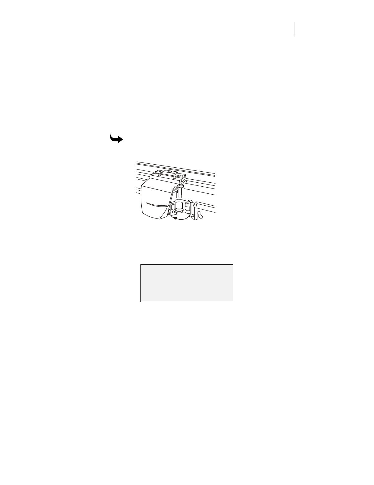
To turn on the plotter
1 Close and latch the tool holder as shown below.
5
2 Plug in the plotter power cord to a wall receptacle.
3 Turn on the power switch located on the front left side of the plotter.
The plotter completes the start-up sequence, then the Main Menu
appears in the control panel display.
MAIN MENU
Settings
Mode: Single Menu 1
Job Status: No Job
Adding the ODYSSEY XP to the cutting software
After physically connecting the ODYSSEY XP to the computer, you have
to add the ODYSSEY XP to the list of available plotters in the software.
The addition makes the plotter available for cutting. If you are an
OMEGA or GA user, follow the instructions in the Reference manual to
add the ODYSSEY XP as the default plotter. If you are using non-Gerber

CHAPTER 2
6
Getting Started
software, refer to the software manual for instructions for adding the
plotter in that software.
Loading material
The ODYSSEY XP cuts and plots a wide variety of vinyl film, masks, and
papers. Always use Gerber-authorized materials for highest quality.
CAUTION: Do not load the material with a tool installed in the tool
holder. Loading material into the plotter with the tool installed can
result in damage to the blade or the material.
CAUTION: Check the material edge for irregularities that could cause
tracking problems. If the material has an irregularity bigger than a
sprocket hole on punched material, turn skew off. (See page 12.)
Tip: To prevent material edge irregularities, always store material horizontally
or vertically on the left edge.
Material loading consists of three steps:
mounting the roll on the plotter
♦
loading the material into the plotter
♦
verifying the material alignment
♦
In addition, you may need to:
cut clear material
♦
turn off skew control
♦
check and measure the available cutting area
♦
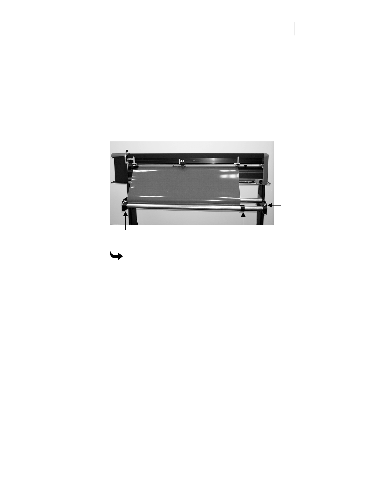
Mounting the roll on the plotter
There are three material roll stops that should be installed on one of the
two material rollers (instructions for installing them are in the ODYSSEY
XP unpacking, assembling, and repacking instructions). The right edge of the
one on the left (as you face the plotter from the rear) should be aligned
with the alignment mark on the plotter platen. The center stop should be
moved against the right edge of the material roll to prevent the roll from
“walking” during cutting. The right stop should be pushed against the
right material roller support and tightened so that it can act as a friction
brake on the roller. The material rollers are installed on the brackets
behind the plotter (as shown below).
Left stop (aligned with mark on platen)
Note : Dampener bar not shown in this view.
To mount the material roll on the plotter
Center stop
7
Right stop
pushed
against
material
roller
support.
Note the
white stop
set screw.
1 Slide the material roller with the stops to the left as you slide the right
stop to the right so that the right stop puts a light pressure on the
material roller support, then tighten the white stop set screw. (You
may need to periodically readjust this stop as it wears. If the plotter
seems to be putting too much force on the material during pulldown,
readjust the stop to loosen the pressure on the material roller support.)
2 Verify that the right edge of the left roll stop is aligned with the
alignment mark on the platen, then tighten the stop set screw. You
should not have to reposition this stop unless the material is not
aligned with the alignment mark on the platen.
3 Put the roll on the material rollers between the left and center stops
and with the free end of the material toward you.
CHAPTER 2
8
Getting Started
4 Push the center stop against the right edge of the material roll, then
tighten the stop set screw. (If you change the size of the material, you
will need to change the position of this stop.)
Loading the material into the plotter
The material is driven through the plotter by the grit wheels (located in
the platen) when it is trapped between the pinch and grit wheels.
Therefore, the location and alignment of these wheels is important when
loading material.
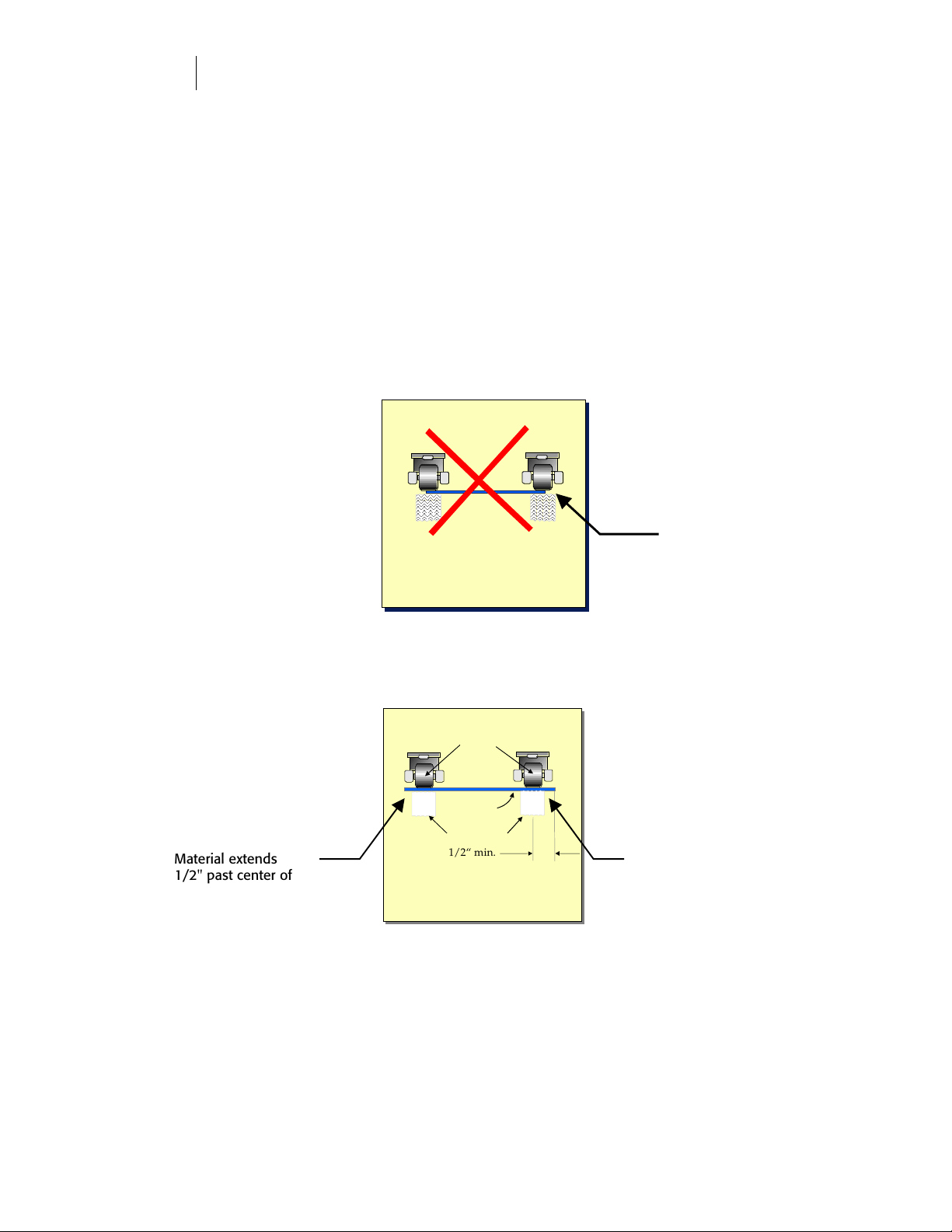
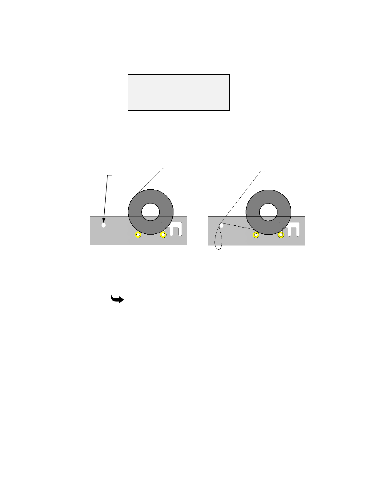
The figures show the position of the material with respect to the pinch
and grit wheels. When material is loaded correctly, the material edge
will extend past the center of both grit wheels by 1/2" (1.3 cm).
Material extends
1/2" past center of
adjustable grit wheel.
Wrong
Material inside pinch wheels
Pinch Wheels
Material
Grit wheels
1/2“ min.
Correct
Material safely outside pinch wheels
Material does not
extend to end of grit
wheels.
Material extends
1/2" past center of
fixed grit wheel.
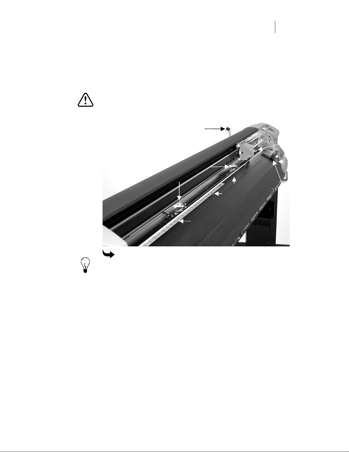
To help you locate and align the grit and pinch wheels, there is a
measuring scale on the platen. Use the lower scale inch readings for
material up to 25" wide. Use the upper scale inch readings for material
more than 25" (64 cm) wide. When you slide the material width
adjustment handle to set the grit wheels for the material width, both the
left and center grit wheels move as a unit. When you slide the pinch
wheels, both the left and center pinch wheels move as a unit.
CAUTION: Raise the pinch wheels off the grit wheels (push the pinch
wheel lever toward the back) when the ODYSSEY XP is not in use.
This prevents creating flat spots on the wheels.
Pinch wheel lever
9
Right pinch
and grit wheel
Pinch wheels
with grit wheels
underneath
Material (width)
sensors
Measuring scale
To load material into the plotter
Tip: Use the left and right slew keys on the control panel to move the carriage
near the center to make loading material easier. For information on using the
slew keys, refer to “Learning the control panel” on page 20.
1 Raise the pinch wheels off the grit wheels by pushing the pinch wheel
lever toward the back.
Alignment
mark
Edge sensor
and deflector
CHAPTER 2
10
Getting Started
2 Push in and slide the material width adjustment handle to set the grit
wheels for the material width. If you set the width to the actual
material width, the scale provides a compensation so that the material
properly extends 1/2" (1.3 cm) beyond the center of the left grit wheel.
If necessary, slide the material over the platen and use it to measure
that the material extends properly beyond the center of the left grit
wheel.
3 Slide the pinch wheels directly above the grit wheels.
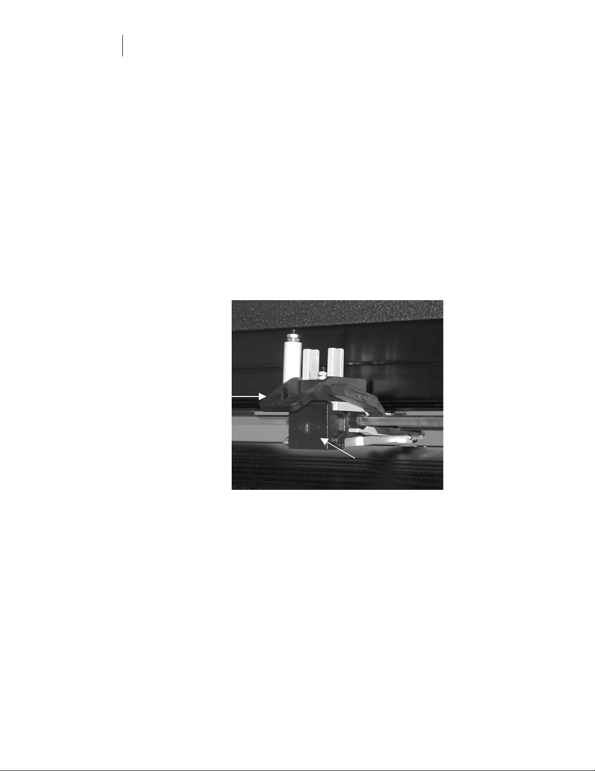
4 Set the controls on the middle pinch wheel as follows:
If you are loading paper or drafting vellum, and it is wider than 25"
♦
(64 cm), pivot the riser block up to prevent the center pinch wheel
from contacting the material.
If you are loading narrow material (less than 25" (64 cm)), pivot the
♦
Hi-Lo Force lever on the center pinch wheel assembly up. If you are
loading material wider than 25" (64 cm), pivot the Hi-Lo Force lever
down. Verify that the lever is in the correct position by looking at the
message display on the control panel.
Force lever
in down
position
Riser block in
up position
5 Slide the material over the platen and under the pinch wheels.
6 From the front of the plotter, slide the material to the right so that the
right edge of the material is exactly aligned with the alignment mark
on the platen and the leading edge of the material is beyond the front
edge sensor. Make sure the material runs under both the front and
rear edge sensors and deflectors.
11
7 Pull the pinch wheel lever toward the front to clamp the material
between the grit and pinch wheels.
8 The control panel displays the following:
SELECT MATERIAL TYPE
Sheet Roll
Press F1 or F3
9 Press either F1 (sheet) or F3 (roll) to select the material type. For
information on using the F1, F2, F3, and F4 function keys, refer to
“Learning the control panel” on page 20.
Note: After pulldown (See page 43), the Odyssey XP will return the material to
the starting position. Do not rewind the surplus material. Allow it to drape over
the dampener bar which promotes a smooth material feed to the cutting tool.
Dampener bar
Material path before pulldown Material path after pulldown
Verifying the material alignment
After you load the material, run auto alignment. The time to perform this
process varies with the amount of error detected.
To perform the material alignment sequence
1 When the display shows
2 The display shows
pinch wheels.
3 The display changes to
material is moved back and forth as the edge is aligned.
4 When the material is properly aligned, the Main Menu appears.
Locating Pinch Wheels
Auto Align Material?
, press F3 (Yes).
while the carriage locates the
Material Auto Align in Progress
while the

CHAPTER 2
12
Getting Started
5 If an error is detected, the display shows
indicate improper loading
To check and reload material
1 Make sure the material roll stops are in the correct position and that
the roll hasn’t “walked” during the material alignment sequence.
2 Remove and reload the material.
3 Make sure the material runs under both the front and rear edge
sensors.
4 Make sure the grit wheels, pinch wheels, and pinch wheel lever are in
the correct position.
5 If the right edge of the material is damaged, or if the sheet is small
(typically shorter than 25" (64 cm)), select No for
and turn skew control off as described later in this section.
Cutting clear material
Clear (transparent) material (such as Clear Enamel Receptive, or any
material with a clear edge) is not detected by the optical edge sensors.
Auto alignment, skew, and material out indications are not in effect
because the material is invisible to the optical edge sensors. When using
clear material, the following special instructions apply.
Reload Material. Sensors
.
Auto Align Material?
To use clear material
1 Load and manually align the material to make sure it is straight.
2 Pull the pinch wheel lever forward. The message
appears.
3 Press F4 (Ignore).
4 Press F3 (Search) to locate the pinch wheels.
5 Run the job.
Note: Not all “clear” materials go undetected at first. If you are having
difficulty with a material you believe to be “clear,” turn off skew control as
described in the next paragraph.
Turning off skew control
Skew control maintains material edge alignment during operation. The
two material edge sensors monitor material edge movement to eliminate
No Material Found

13
drift. When running some materials, it is recommended that skew
control be turned off. In most of these cases, the plotter will not see the
material at all, and will automatically run with skew off. To avoid any
instances were skew might be turned on or off during running of these
materials, it is suggested that skew control be turned off before loading
the material and the auto-align feature not be used. Align the material by
hand/eye using the guide marks on the plotter extrusions near the edge
sensor. If the plotter asks to auto-align the material, press the Function
key F1 for "No".
Note: Normally, skew control is ON. If you are running scrap material,
transparent materials, or material with an uneven edge, turn skew control off.
Turn skew off if runnng the following materials:
• 225 Clear Enamel Receptive (without the black edge stripe)
• GerberVision
• Gerber Sandblast Stencil #521 and #522 (edge-stripped and on clear liner)
• Imagecast Eclipse
• LexEdge Clear
• LexEdge II
• LexEdge II Polished/Clear
• Dusted Crystal
• Frosted Crystal
• Gerber 20-pound Paper
• Any non-Gerber clear material with clear backing
• Any non-Gerber paper 20-pound or less
Gerber does not recommend using the ODYSSEY XP to cut screenprint films
such as Rubylith.
When you return to using other material, make sure you turn skew
control back on (normal or short).
To turn skew control off
1 At the Main Menu, press F4 (Menu 1).
2 At the Menu 1 display, press Skew (F4).
3 The skew display appears and shows that skew is ON - norm. Press
either F3 or F4 to step through the choices (ON − norm, ON − short for
material less than 48" (122 cm) wide, or OFF).
CHAPTER 2
,
14
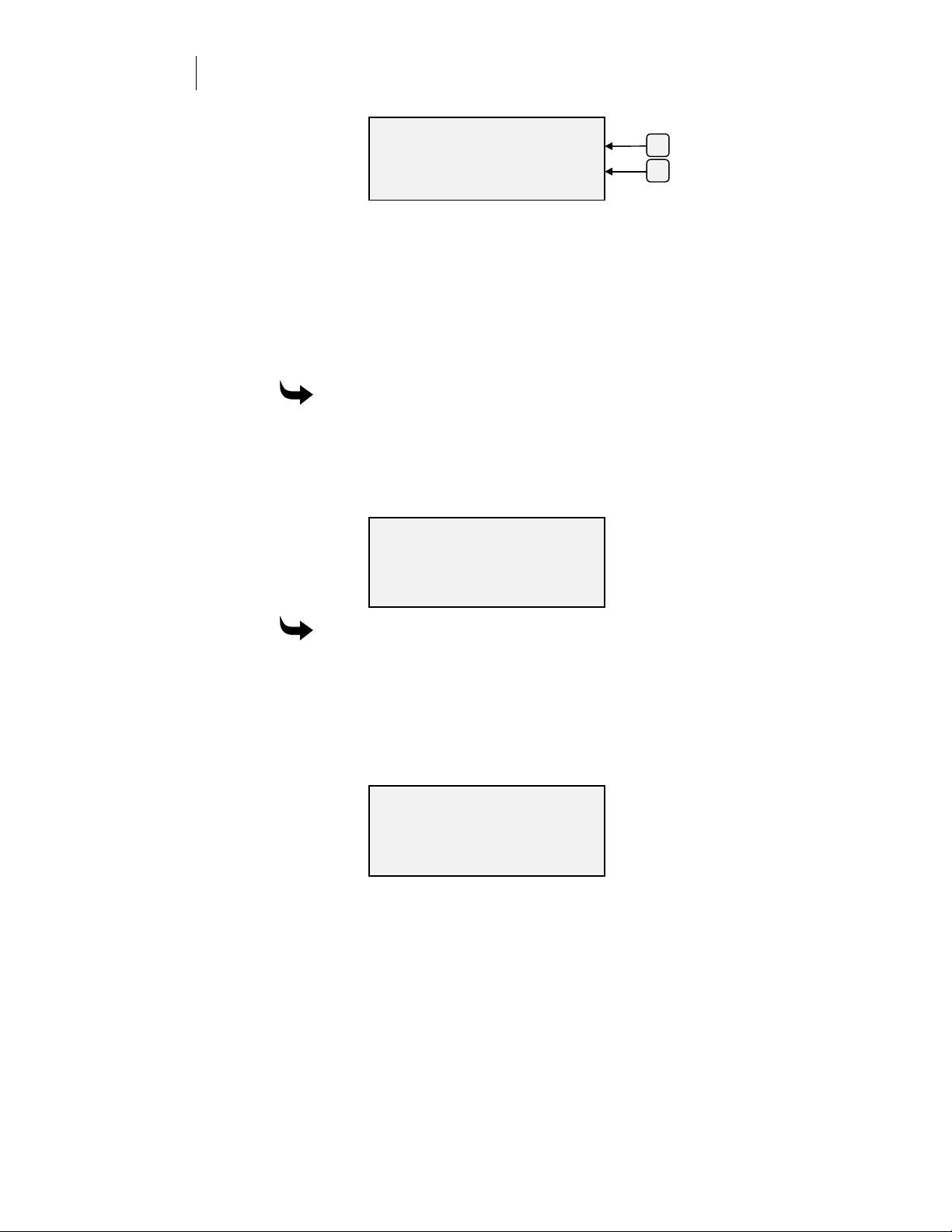
Getting Started
SKEW
Skew Control: +
ON −−−− norm
ENTER Key to Accept
-
F3
F4
4 Press Enter twice to return to the Main Menu.
Checking and measuring the available cutting area
After you load material, you can check and measure available cutting
area dimensions. After you load material, the plotter checks the width
available for cutting. For sheet material, it also checks the length. This
feature lets you plan and lay out jobs to make efficient use of material.
To check a cut area
1 At the Main Menu, press F4 (Menu 1).
2 Press F1 to check the cut area. The display shows the dimensions of
the job, which is slightly less than the material dimensions. If roll
material is used, the length appears as 0.
Material Cut Area
Length: Width:
42.00 in 35.50 in
(107.52 cm 90.17 cm )
To measure a cut area
1 At the Main Menu, press F4 (Menu 1).
2 Press F2 to measure an area.
3 Use the left and right slew keys on the control panel to slew the
carriage to the point where you want to begin.
4 Press F4 to reset the display to zero.
Length: Width:
0.00 in 0.00 in
(0.00 cm 0.00 cm )
Slew
ENTER, F4 = Reset
5 Use the left and right slew keys to move the carriage.
distance the tool moved from the zero set point. Use the up and down
slew keys to move the material.
moved from the zero set point.
Installing tools
The knife, pen, and optional pounce tools are all installed into the tool
holder the same way. This paragraph provides information on installing
a tool. For information on changing and adjusting blades, see Chapter 4,
“Tools and Tool Settings”.
If you are using a Gerber target alignment tool to align the tool holder
with printed registration marks on the material, refer to “Aligning with
printed images“ on page 28.
To install a tool
1 Move the carriage to the middle of the plotter by pressing the left or
right slew key.
Width
Length
shows the distance the material
15
shows the
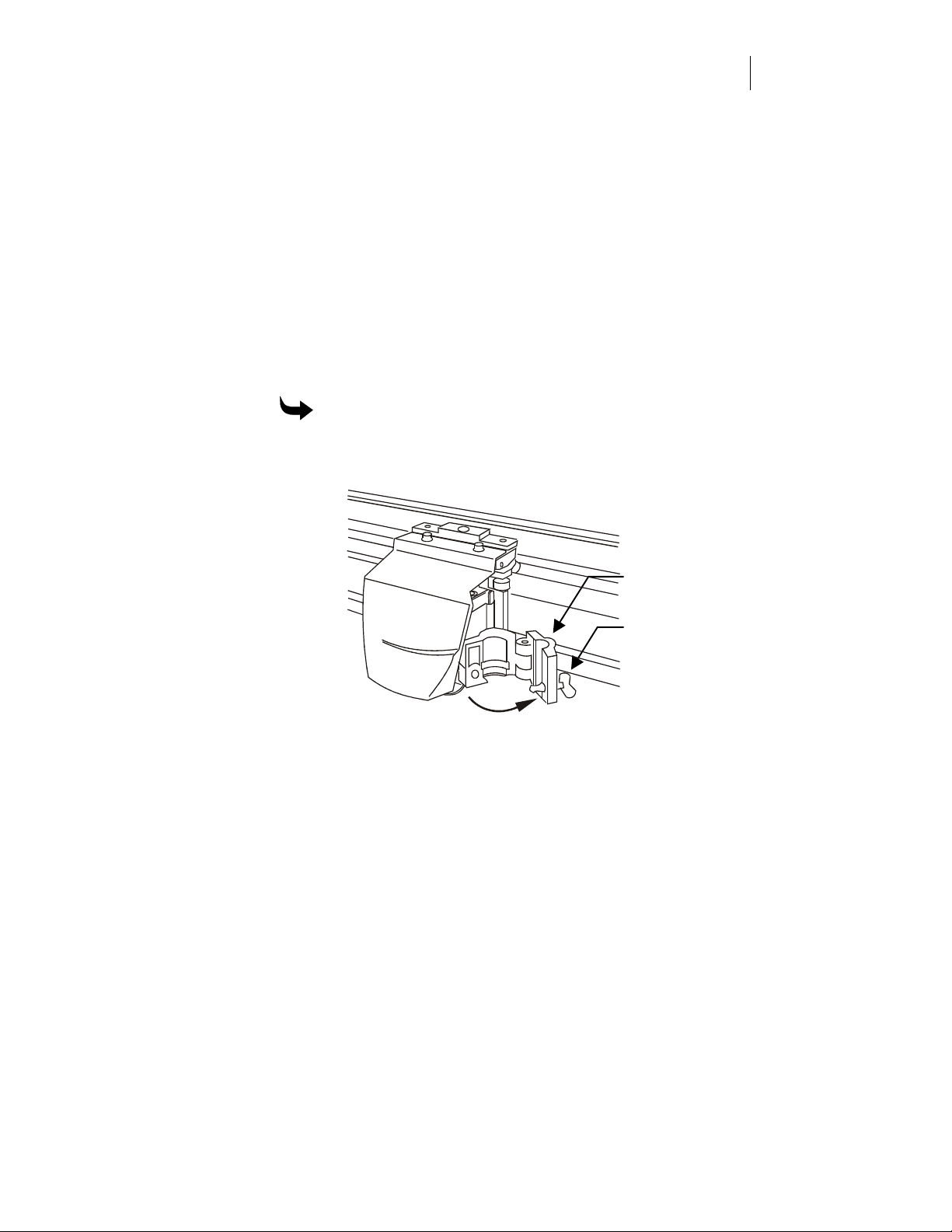
Tool holder
Latch fastener
2 Open the tool by turning the latch fastener counterclockwise and
gently pulling the holder open.
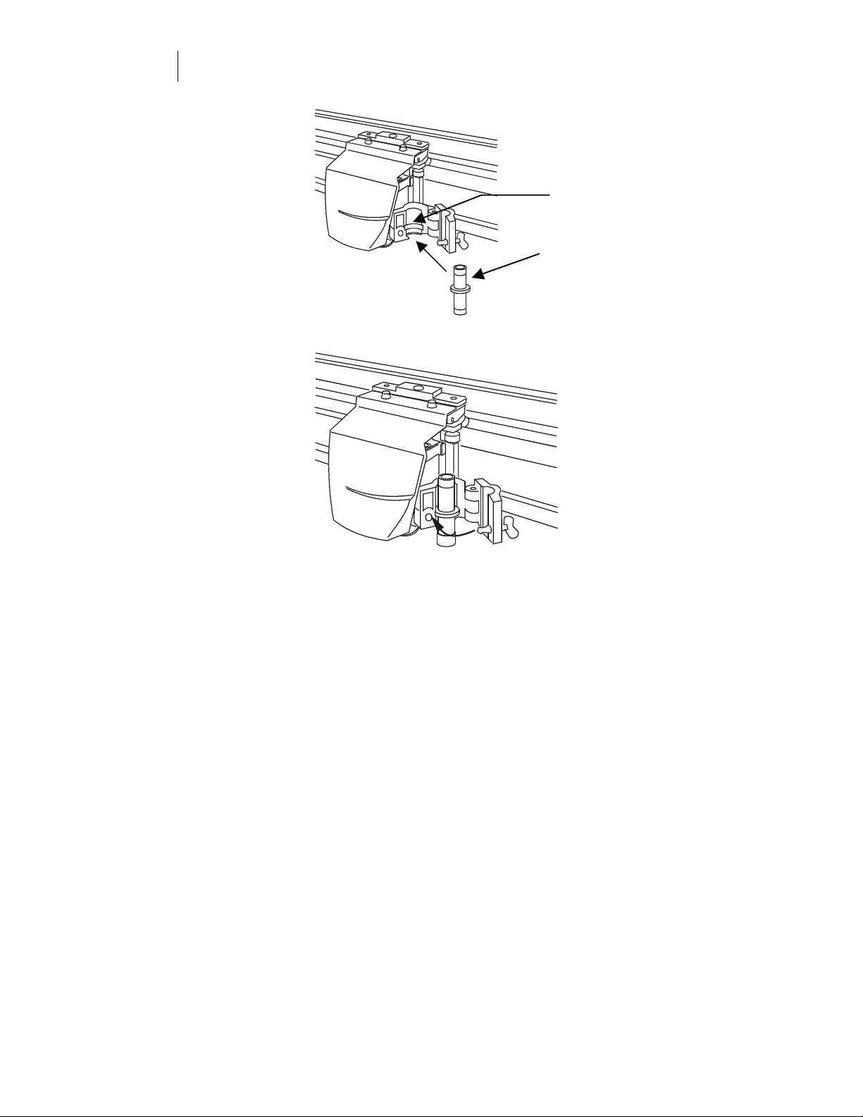
3 Place the tool into the tool holder, making sure that the tool flange fits
into the groove.
CHAPTER 2
16
Getting Started
Groove
Flange
4 Close the holder and secure it by turning the latch fastener clockwise.
Changing knife blades
Knife blades dull slightly over time. Blade wear is normal and always a
gradual change. Adjusting tool settings, as described in Chapter 4, Tools
and Tool Settings, can extend blade life.
Blades are ground to a controlled length and cannot be resharpened. A
sudden decline in cutting quality could indicate that the blade was
chipped or damaged. Replace and discard any chipped blade.
In addition, you may need to change a knife blade if you use different
materials. The following chart summarizes knife blade angles and
material used.
Blade angle Examples of material used with specific blades
30° Thin materials, such as Ulano and Autotype
45°
60° Thick materials, such as Sandblast and
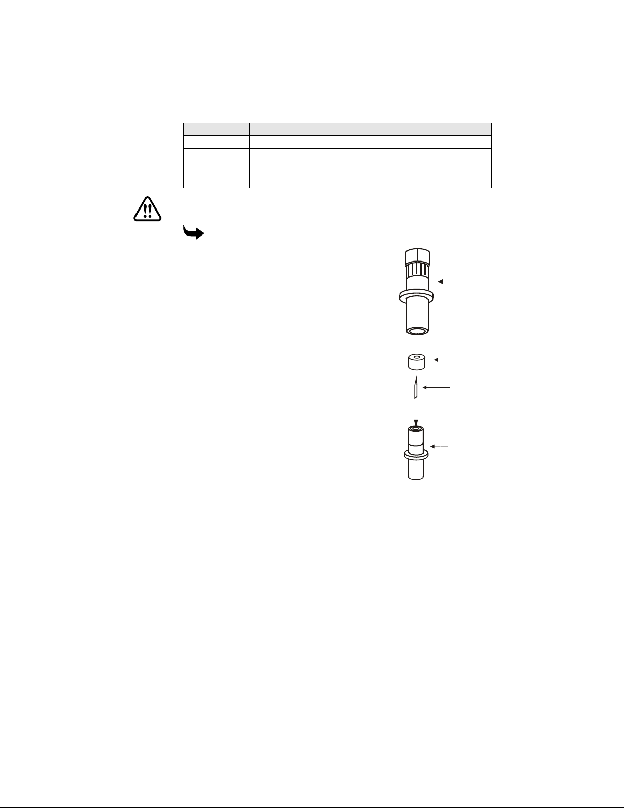
WARNING: Handle the blades carefully. Blades are extremely sharp.
They are brittle and can easily chip.
To change the blade
1 Hold the knife tool so the blade points
toward the ceiling.
2 Remove the adjustment cap by turning it
counterclockwise until it comes off
completely.
3 Remove the old blade by pulling it straight
out with a pair of tweezers.
4 Use tweezers to put in the new blade. Be
careful not to touch the cutting edge with
the tweezers.
5 Press the blade tip lightly with the flat of
your fingernail to ensure it is all the way
into the blade holder.
6 Put the adjustment cap back on carefully
and turn it clockwise.
Most materials, such as Scotchcal 220
GerberMag
Knife
Tool
Adjustment
Cap
Blade
Blade Holder
17
7 Adjust the blade by following the
directions in the next paragraph,
“Adjusting knife blade exposure.”
Adjusting knife blade exposure
Cut quality is directly related to the correct blade exposure for the
material being cut. Too little blade exposure can make weeding difficult.
Too much blade exposure combined with too much force can cut
through the material backing and decrease cut quality.

CHAPTER 2
18
Getting Started
The blade holder has hash marks around it. The adjustment cap has a
pointer, which lines up with the hash marks. One hash mark equals
0.001" (1 mil or 0.0254 mm).
Tip: The autocut off feature might require more blade exposure than normal.
To set the blade exposure
1 Hold the knife tool with the blade toward the ceiling. The blade
should extend beyond the end of the adjustment cap by approximately
the thickness of two sheets of paper. (This is the correct setting for
Scotchcal 220 material. Other materials require different exposure.)
2 To extend the blade, turn the adjustment cap clockwise. To retract the
blade, turn the adjustment cap counter clockwise.
CAUTION: When performing the next step, do not press too hard on
the material. Too much pressure can damage the blade.
3 Place a piece of the material you will be cutting on a flat surface and,
pressing gently, scribe a circle with the tool by hand.
4 Weed the circle. If it weeds properly without cutting into the backing,
the blade exposure is correctly set for that material.
5 If the material has not been cut all the way through, turn the
adjustment cap clockwise one or two hash marks to expose more
blade. Go back to Step 3. Repeat the procedure until the scribed circle
weeds properly without cutting the backing material.
6 If the backing material has been cut, turn the adjustment cap counter
clockwise to decrease the blade exposure. Go back to Step 3. Repeat
the procedure until the backing material is no longer cut and the
scribed circle weeds properly.

Chapter 3: Running Jobs
This chapter describes the control panel and its use and explains how to
run jobs :
learning the control panel
♦
running jobs
♦
pausing, restarting, and canceling jobs
♦
automatically cutting a job off the roll
♦
making jobs fit
♦
cutting graphics printed on the EDGE, EDGE 2, and MAXX
♦
19
CHAPTER 3
20
Running Jobs
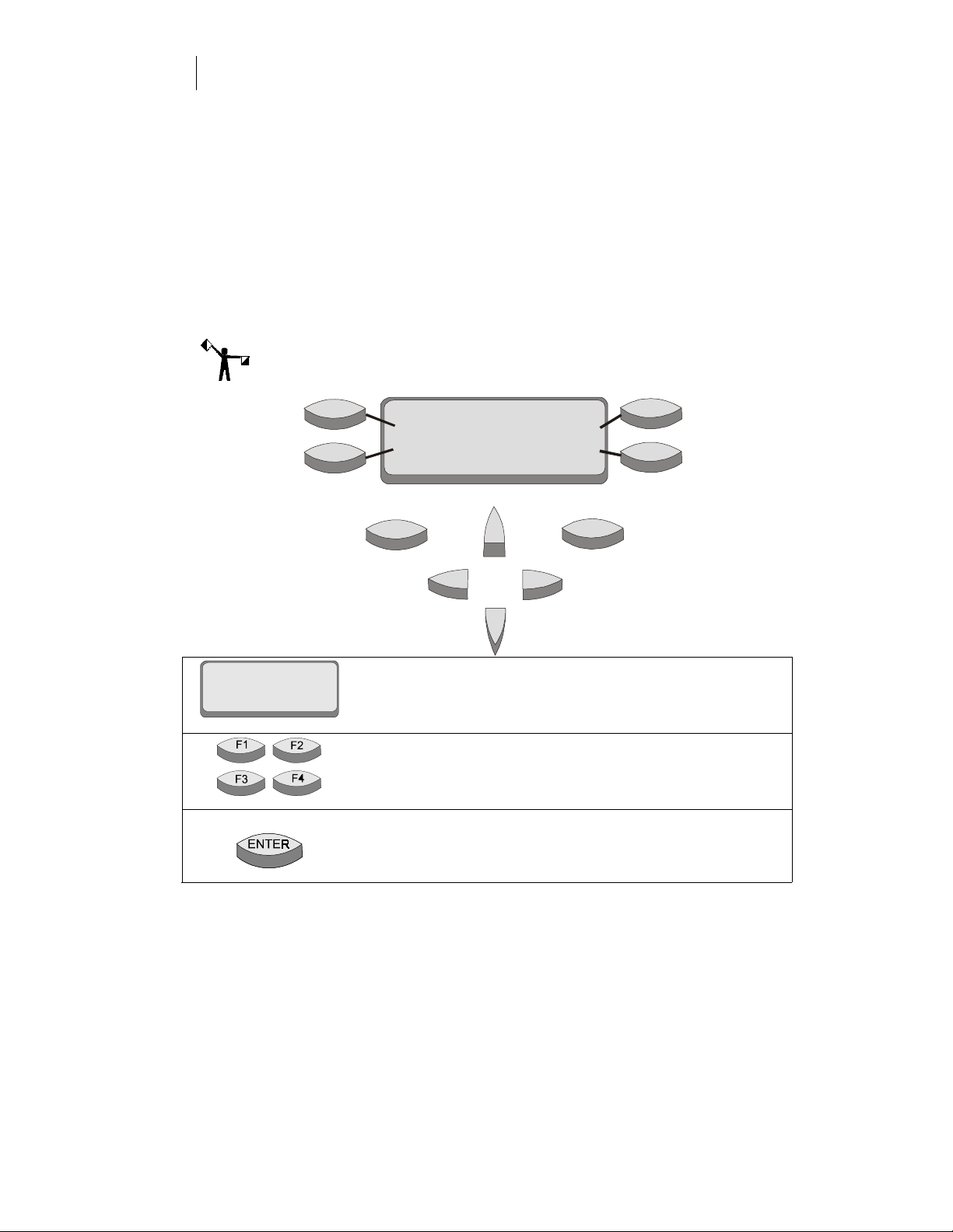
Learning the control panel
The plotter control panel provides functional control and status displays.
The control panel consists of:
the message display
♦
four menu selection function keys (F1, F2, F3, F4)
♦
two control keys (ENTER and CANCEL)
♦
four slew keys
♦
Note: For an outline of the menu structure, please refer to the reference card
included with this manual.
F1
F2
Menu item
Menu item
ENTER
TITLE
Instruction s
Menu item
Menu item
CANCEL
F3
F4
The message display shows menus, instructions, system and
job status, and messages. Each menu has a title (for example,
MAIN MENU). To step through menus, press the function
keys.
The F1, F2, F3, and F4 function keys select other menus and
change parameter values or settings. Their function is based
on the text in the display associated with each function key.
In the settings menu, the ENTER key saves settings.
From a submenu, it returns to the MAIN MENU.
 Loading...