

Page 1

GERBER MAXX 2™
Owner’s Guide
Page 2

Page 3

Copyright Notice
COPYRIGHT 2002 Gerber Scientific Products, Inc. All Rights Reserved.
This document may not be reproduced by any means, in whole or in part, without written
permission of the copyright owner.
This document is furnished to support the GERBER MAXX 2 wide-format thermal printer. In
consideration of the furnishing of the information contained in this document, the party to
whom it is given assumes its custody and control and agrees to the following:
1 The information herein contained is given in confidence, and any part thereof shall not be
copied or reproduced without written consent of Gerber Scientific Products, Inc.
2 This document or the contents herein under no circumstances shall be used in the
manufacture or reproduction of the article shown and the delivery of this document shall not
constitute any right or license to do so.
Printed in USA
GSP and EDGE are registered trademarks of Gerber Scientific Products, Inc. GERBER MAXX, MAXX 2,
MAXX READY, OMEGA, ThermApprove, GerberTone, GerberColor Spectratone, ODYSSEY, FasTrack,
Gerber FastFacts, and Support First are trademarks of Gerber Scientific Products, Inc. Adobe PhotoShop
is a registered trademark of Adobe Systems Incorporated. Chemtronics and Ultrajet are registered
trademarks of Chemtronics, Inc. 3-IN-ONE and WD-40 are a registered trademarks of the WD-40
Company. CorelDRAW is a registered trademark of Corel Corporation. HPGL is a trademark of HewlettPackard Company. Microsoft is a registered trademark of Microsoft Corp. PANTONE and other
Pantone, Inc. trademarks are the property of Pantone, Inc. Windows is a registered trademark of
Microsoft Corp. in the U.S. and other countries.
Page 4

FCC Notice
Warning: Changes or modifications to this unit not expressly approved by the party responsible
for compliance could void the user’s authority to operate the equipment.
Note: This equipment has been tested and found to comply with the limits for a Class A digital
device, pursuant to Part 15 of the FCC rules. These limits are designed to provide reasonable
protection against harmful interference when the equipment is operated in a commercial
environment. This equipment generates, uses, and can radiate radio frequency energy and, if
not installed and used in accordance with the instruction manual, may cause harmful
interference to radio communications. Operation of this equipment in a residential area is likely
to cause harmful interference in which case the user will be required to correct the interference
at his own expense.
1284-1994 Compliant cables must be used with this unit to ensure compliance with the Class A
FCC limits.
This Class A digital apparatus meets all requirements of the Canadian Interference-Causing
Equipment Regulations.
Cet appareil numérique de la class A respecte toutes les exigences du Règlement sur le matériel
brouilleur du Canada.
Page 5

Contents
Chapter 1: Introduction............................................................................................................. 1
In this manual .......................................................................................................................................... 1
Conventions ............................................................................................................................................. 1
Customer support ...................................................................................................................................2
Chapter 2: Getting to Know the GERBER MAXX 2............................................................... 3
Basic requirements .................................................................................................................................. 3
Environment and temperature importance...................................................................................... 3
Using MAXX READY material.............................................................................................................. 3
Vinyl care .............................................................................................................................................. 3
Vinyl storage......................................................................................................................................... 4
Overview of the MAXX 2....................................................................................................................... 5
The printer table ...................................................................................................................................... 6
The printhead carriage assembly.......................................................................................................... 6
Loading the material............................................................................................................................... 7
The foil cassettes...................................................................................................................................... 9
Loading the foil cassette......................................................................................................................... 9
Straightening wrinkles in foil ........................................................................................................... 11
Loading the cassettes in the MAXX 2................................................................................................. 11
Chapter 3: Understanding the MAXX 2 Control Panel ..................................................... 12
Control panel keys ................................................................................................................................12
MAXX 2 power up sequence ............................................................................................................... 14
Entering menu selections ..................................................................................................................... 14
Starting jobs............................................................................................................................................ 14
Run single mode................................................................................................................................. 14
Run continuous mode .......................................................................................................................15
Quick Start operation............................................................................................................................ 15
Stopping and restarting jobs................................................................................................................ 15
Pausing jobs and restarting a job ..................................................................................................... 16
Reprinting the last job........................................................................................................................... 16
Queuing jobs at the MAXX 2 control panel....................................................................................... 16
Displaying a list of jobs in the View Job Details ............................................................................ 16
Displaying detailed information about each queued job .............................................................17
Re-positioning a job in the queue..................................................................................................... 18
Deleting jobs from the queue............................................................................................................ 18
Adjusting the pull distance when slewing material......................................................................... 19
Updating the MAXX 2 firmware......................................................................................................... 19
Chapter 4: MAXX 2 Care and Cleaning.................................................................................21
Recommended MAXX 2 cleaning materials...................................................................................... 21
Daily cleaning procedures ................................................................................................................... 21
Cleaning the vinyl squeegees and magnet bars............................................................................. 22
Cleaning the edge sensor strip ......................................................................................................... 23
Cleaning the platen............................................................................................................................ 23
Inspecting and refilling the wiper box ............................................................................................ 24
Cleaning the ways, lead screw, and ball screws............................................................................ 24
Cleaning the material catching baskets........................................................................................... 24
The importance of cleaning the printhead......................................................................................... 25
Page 6

Automatic head cleaning .................................................................................................................. 27
Manually cleaning the printhead..................................................................................................... 27
Cleaning foil cassettes........................................................................................................................ 31
Chapter 5: Printing Jobs .......................................................................................................... 33
Setting up and sending the job............................................................................................................ 33
Determining the status of each bay..................................................................................................... 33
Reducing the recorded amount of foil in a cassette.......................................................................34
Printing the job ......................................................................................................................................34
Viewing foil and material information for the job......................................................................... 35
Printing test jobs.................................................................................................................................... 37
Chapter 6: Modifying MAXX 2 Print Settings......................................................................39
Printing the Pull Out or Pull Back Check prints ............................................................................... 39
Modifying the Darkness Adjust setting ............................................................................................. 40
Modifying the Seam Adjust setting .................................................................................................... 41
Chapter 7: Understanding Messages ................................................................................... 43
Status messages ..................................................................................................................................... 43
Error Messages ......................................................................................................................................46
Index ............................................................................................................................................50
Page 7

Chapter 1:
Introduction
Congratulations on your purchase of the GERBER MAXX 2 thermal printer. This wide-format
printer combines the reliability and superior printing ability of the revolutionary GERBER
EDGE with the utility of printing on 36" wide material.
In this manual
The following chapters introduce you to the MAXX 2, describe the printing process and
procedures, and show you how to maintain your printer for maximum quality output.
Getting to Know the GERBER MAXX 2 contains photographs and descriptions of the major
parts of the printer and provides instructions for loading vinyl and foil cassettes.
Understanding the MAXX 2 Control Panel describes the control panel, run modes, starting and
stopping jobs, the Job Queue, and updating the MAXX firmware.
MAXX 2 Care and Cleaning includes information on the proper cleaning of the MAXX 2, foil
cartridges, and materials. Extensive in-house and field-testing reveals cleanliness is an
important factor impacting printing quality.
Printing Jobs describes in a step-by-step sequence how to print jobs on the MAXX 2. This
chapter also includes a list of test jobs and their purpose.
Modifying MAXX 2 Print Settings explains Pull Check prints and details how to modify the
Print Darkness and Seam Adjust settings to achieve optimal print quality.
Understanding Messages lists display messages that may appear, describes what the messages
mean, and suggests actions in response.
Conventions
The following conventions are used in this addendum:
Tip: A tip contains valuable information that could make the task faster or easier.
Note: A note contains important information that could affect the successful completion of a
task.
CAUTION: A caution statement contains information which, if not observed, could
result in equipment damage.
WARNING: A warning statement contains information which, if not observed,
could result in personal injury.
Page 8

CHAPTER 1
2
Introduction
Customer support
If you have questions regarding using, maintaining, or troubleshooting the MAXX 2, please
contact your Gerber distributor, GSP Field Service for hardware questions, or Technical
Systems Support for software questions.
phone: 800-828-5406 for hardware, 860-644-6971 for software
fax: 860-648-8376
Additional sources of information are:
♦ Gerber FastFacts provides answers to technical and service questions. The telephone
♦ If you are a Support First member, use your toll-free assistance number (for more
e-mail: gspservice@gspinc.com (hardware) or gsptech@gspinc.com (software)
www.gspinc.com
number is 860-648-8040. FastFacts are also available on the web site under “Support.”
information about Support First, call 860-644-6971).
Page 9

Chapter 2:
Getting to Know the GERBER MAXX 2
The GERBER MAXX 2 is a sophisticated machine but is very easy to use. The following pages
introduce the printer and describe basic operation.
Basic requirements
The MAXX 2 is a network device. Your computer must have an Ethernet network card installed
to communicate with the printer. Gerber provides the proper network cables to connect your
computer with the MAXX 2 so that you are up and running without delay.
You must have OMEGA 1.56 or higher to print to a MAXX 2. However, you do not have to
specifically design a job for the MAXX 2.
3
We currently support the Gerber ODYSSEY plotter and the Gerber FasTrack 1300 plotter for
cutting MAXX 2 graphics.
Environment and temperature importance
The room temperature where the MAXX 2 is located should be 68°F to 78°F (20°C to 25.6°C)
with a relative humidity of 20% to 85%. Be sure to allow the equipment and materials to reach
and remain at room temperature for 24 hours before printing.
Using MAXX READY material
The MAXX prints only on GERBER MAXX READY materials. Gerber specially developed
GERBER MAXX READY materials for thermal printing and are the only materials
recommended for use with the MAXX. Gerber continues to qualify more substrates and foils on
an on-going basis. For a list of currently qualified MAXX READY materials see www.gspinc.com.
Gerber recommends printing on only 36" MAXX READY material. Do not use punched vinyl,
material less than 36" in width, or any other material that is not MAXX-qualified. Residue from
the punched vinyl adhesive can cause serious problems that will require service.
Vinyl care
CAUTION: Never clean vinyl with isopropyl alcohol, only clean the vinyl with
distilled water.
The best way to keep the vinyl clean is to always use the material catching baskets. If the vinyl
gets dirty (often the static charge on the vinyl attracts dirt from the rug or floor), the printed job
may show imperfections such as voids, hair lines, or small unprinted areas. Wipe the vinyl with
a clean, lint-free cloth moistened with distilled water. Allow the vinyl to dry completely before
Page 10
CHAPTER 2
g
4
Getting to Know the GERBER MAXX 2
printing as water or moisture can damage the printhead. Before loading vinyl into the MAXX 2,
wipe the ends of the roll with a tack cloth to remove any dirt or dust.
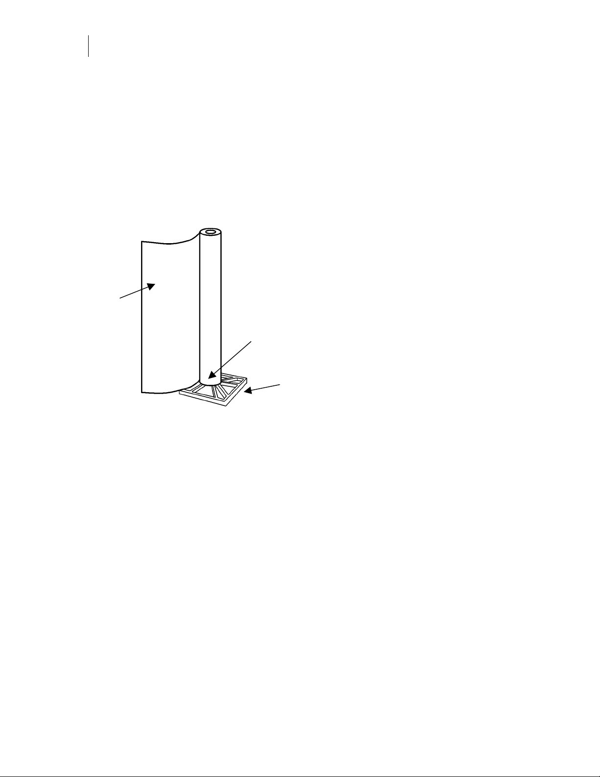
Vinyl storage
When not in use, vinyl should be stored in the original plastic bag to protect it from dust and
dirt. Save the original box for long-term storage of vinyl rolls. Never store the vinyl lying down
or in the MAXX 2 material catching baskets, which can leave impressions on the surface of the
vinyl. Store the vinyl standing on the end of the roll that will be opposite the edge sensors at the
left side of the MAXX 2. Standing the roll on the end that will be used to align the vinyl can
cause print quality problems. To protect the material from the floor, stand the roll on the plastic
plug included with the original packaging.
Backing
sheet side
of vinyl
Stand the roll on this end to avoid
damaging the end of the roll that the
MAXX sensor uses to ali
Stand the roll on the plastic plug
included with the original packaging.
n the vinyl.
Page 11
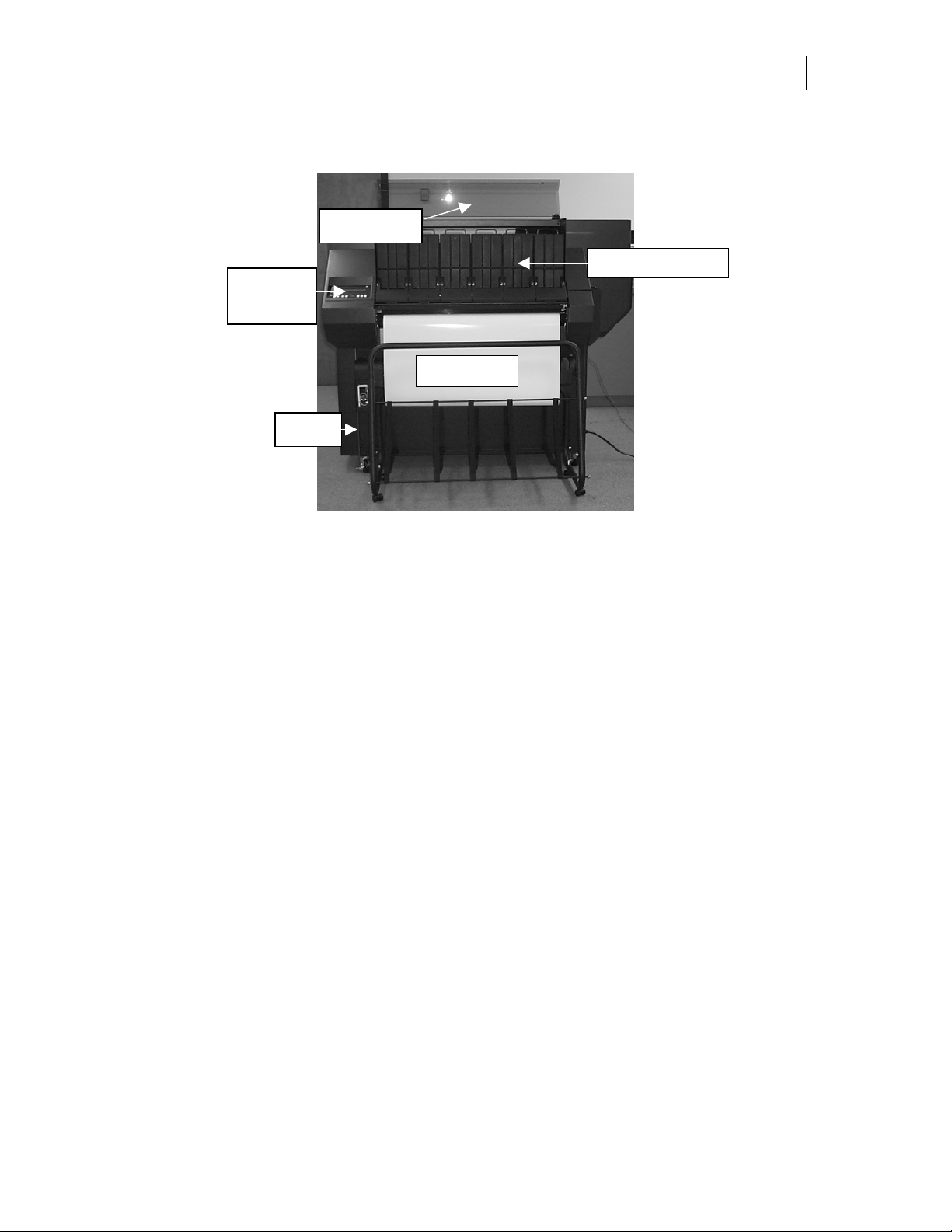
Overview of the MAXX 2
Rack cover
Control
panel
Base
5
Cassettes in rack
Supply roll
The MAXX 2 base houses the control circuitry for the printer. In addition to these electronic
components, a vacuum pump is mounted in the base. The pump comes on automatically at the
start of the printing sequence to hold the material firmly against the platen.
The material supply roll is mounted on the front of the base. A loop of material is automatically
unrolled into the material catching basket to reduce drag on the material advance system
(magnet bars) during printing.
Up to six foil cassettes can be mounted in the cassette rack. The foil can be loaded and unloaded
in the cassettes as required.
The control panel is the interface between the operator and the printer. A message display
provides information and prompts, and the keypad controls the printer functions.
Page 12
CHAPTER 2
6
Getting to Know the GERBER MAXX 2
The printer table
Foil in
cassette
Magnet bars
Platen
Material is pulled through the printer by the magnet bars. The vacuum draws through the holes
in the platen and holds the material flat during printing. The cassette rack stores up to six foil
cassettes. Each cassette is stored in an individual cassette bay.
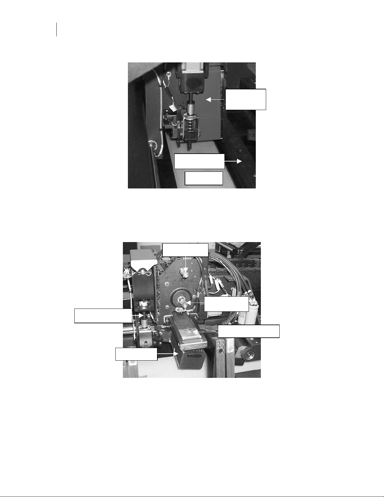
The printhead carriage assembly
Take-up pin
Supply pin
Z axis lead screw
Cassette changer
Printhead
During printing, the supply and take-up cassette pins pull the foil across the printhead. The
printhead is lowered by the Z axis lead screw and motor to press the printhead against the foil
and material when printing. The automatic cassette changer loads and unloads foil cassettes as
required by the job design.
Page 13
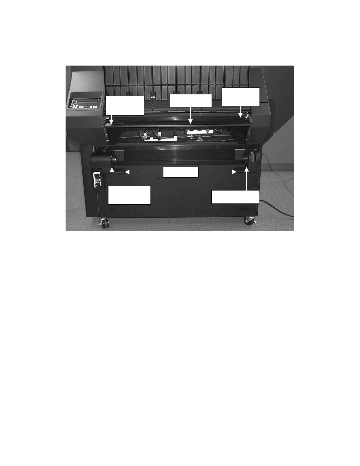
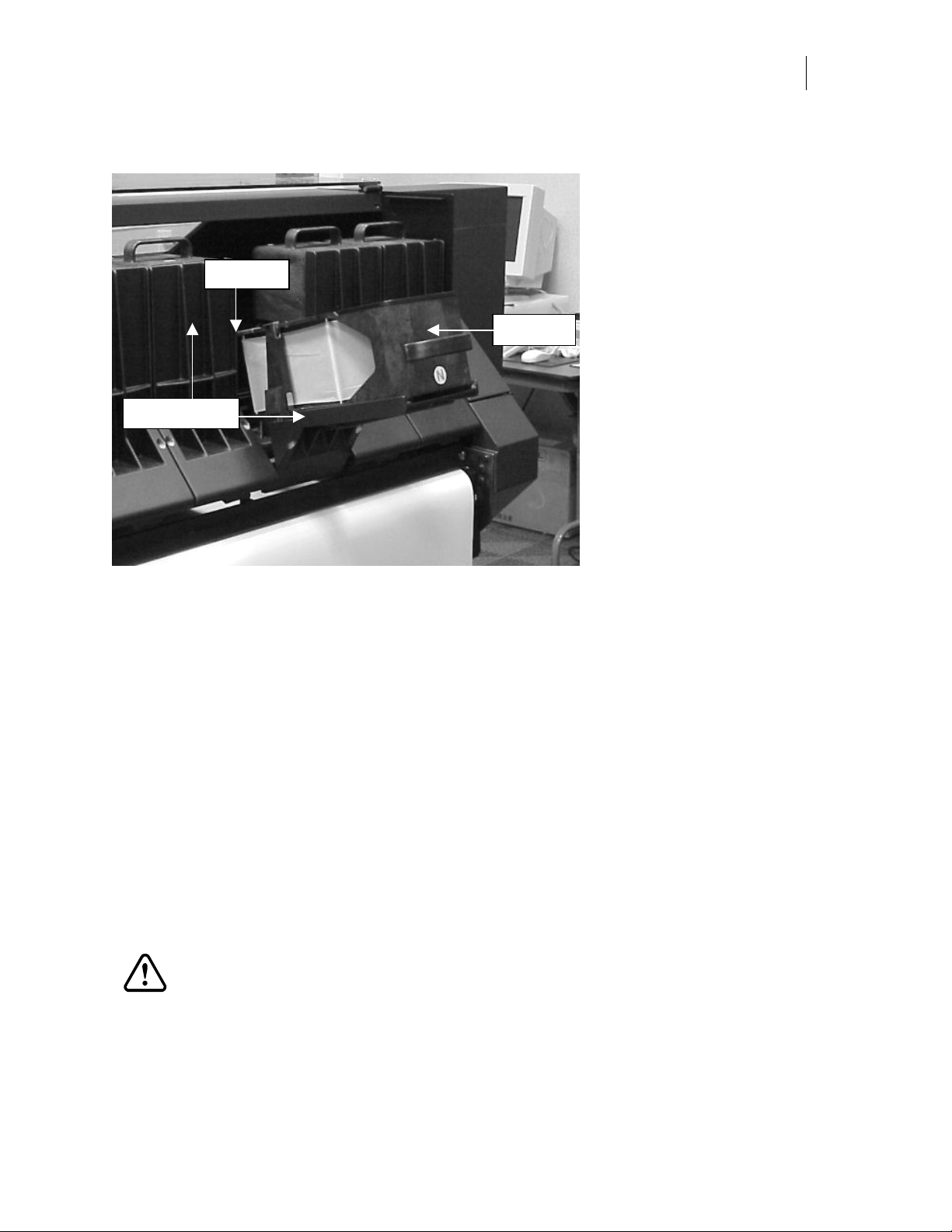
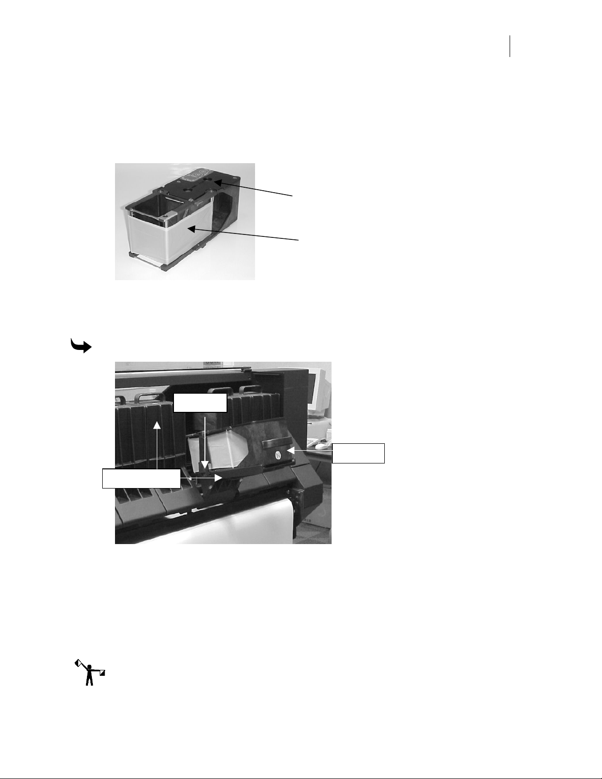
Loading the material
Alignment
line
Material tray
7
Front vinyl
squeegee
Left roll hub
and motor
Right roll hub
The rolls of MAXX READY material are mounted on the roll hubs at the front of the printer.
There is a material loading path illustration on the left material roll hub for guidance in loading
material. Under the roll hubs are roll rests to aid in loading heavy rolls of material.
The left roll hub is stationary, while the right roll hub slides across the front of the base to
accommodate the slight variations in width of the supply roll. The left roll hub is motor-driven
to provide a loop of material, which reduces drag while the material advances through the
printer. When the loop is the correct size, the motor is off.
Before loading the material, lift the material tray up and lock it in the horizontal position. On
the left side of the tray is an alignment line. There is another alignment line on the back of the
table where the vinyl exits. When you load the material, align the left side of the material with
both of these lines before clamping the material with the magnet bars.
Page 14

CHAPTER 2
8
Getting to Know the GERBER MAXX 2
To load the material
1
Raise the material tray.
2
Move the material catching basket away from the front of the base.
3
Slide the right roll hub so that it is the same approximate distance from the left roll
hub as the material width.
4
Unroll some material, then put the roll of material on the left and right roll rests so that
the unrolled material is near the front of the base and the substrate or carrier side is
facing away from the base and toward you.
5
Put the left end of the material core tube on the left roll hub, then raise the right end of
the roll and slide the right roll hub into the right end of the material core tube. Use the
thumbscrew on the right roll hub to lock it into position.
6
Roll the material catching basket so that it locks in place in the basket clips in front of
the base.
7
Unroll several feet of material behind the vinyl flag and into the material catching
basket.
8
Turn on the printer. The message display is
initializing sequence is complete and the display is
Initializing
Ready for Print job
. Do not touch any keys until the
, then press LOAD
VINYL on the control panel.
CAUTION: When performing the next step, be certain that the vinyl slides between
the magnet bars and on top of each bar’s keeper plate. If the vinyl goes under the
keeper plate, it will get damaged. In order to keep the mag bars clean, make certain
that the leading edge of the vinyl is clean cut and that there is no residual adhesive.
9
Feed the material across the material tray, under the front vinyl squeegee, through the
two magnet bars, under the rear vinyl squeegee, and out of the back of the table. The
material should extend approximately 4" beyond the rear vinyl squeegee.
Tip: When sliding the material on the material tray, it may help to tilt the material slightly to
get one corner under the front vinyl squeegee and magnet bar as you push the material into
the printer.
10
Align the material with the alignment lines on the front material tray and on the back
of the table. Careful alignment of the vinyl at the front and back of the MAXX shortens
the automatic alignment sequence.
11
Press LOAD VINYL on the control panel to clamp the material with the vinyl
squeegees and magnet bars.
12
Lower the material tray.
Page 15
The foil cassettes
y
p
Bay sto
Cassette ba
9
Cassette
Each foil cassette contains a continuous ribbon of foil. When the supply roll is low or empty, the
control panel display prompts you to load more foil in the cassette. The cassettes are “smart”
cassettes. A cassette reader button inside the supply roll core monitors the amount of foil used,
the amount remaining on the supply roll, and the color of the foil. Metal contact strips on the
bottom of the cassette touch contact strips on the bay stops to transmit this information to the
MAXX 2. The control panel also displays which foil cassette is loaded in each bay. The
printhead carriage assembly automatically loads the foil cassettes and lowers the printhead to
the material for printing.
Loading the foil cassette
The foil in the package is on two rolls − a supply roll (the larger roll) and a take-up roll (the
smaller roll). There is a clear stiff leader at the start of the supply roll to make loading the foil
easier. The supply roll also contains a cassette reader button that monitors the amount of foil
used, the amount remaining on the roll, and the foil color. This information is sent to the control
panel for display and is also used to identify which cassette bay contains the proper foil color
for the job.
CAUTION: The foil is fragile. When you handle the supply roll, be very careful
that it does not “telescope” (the inside part of the roll sliding out of the outer part of
the roll). If this happens, the foil may be damaged, it will be difficult to load, and it
may cause wrinkling or other printing problems. Do not touch the unused foil.
Fingerprints on the foil will create areas on the foil that will not print on the
material.
Page 16
CHAPTER 2
10
Getting to Know the GERBER MAXX 2
When loading the cassette, load the supply roll first. The memory reader button goes on the
front end of the roll (nearest the outside of the cassette). The cover has a label showing you the
foil path.
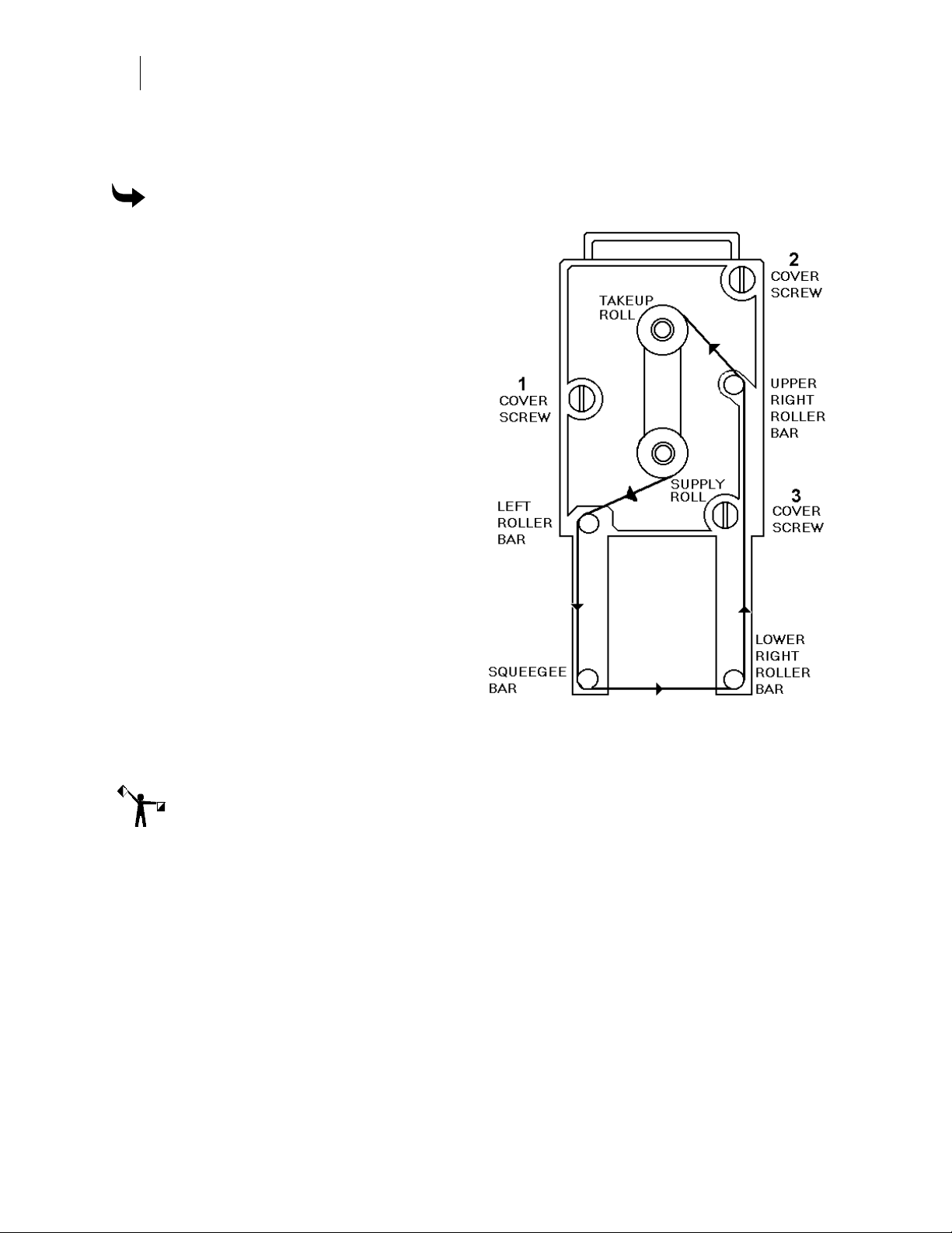
To load the foil in the cassette
1
Use a screwdriver to turn the three
cover screws 1/4 turn counterclockwise to loosen them, then lift off the
cassette cover.
2
Unwrap the new foil.
3
Slide the supply roll on the lower
cassette shaft.
4
Feed the leader and take-up roll
through the side of the cassette,
around the left roller, squeegee bar,
and lower right roller bar as shown
in the illustration. The dull side of the
foil will be facing away from the
cassette body.
5
Feed the take-up roll through the
trapezoidal window on the right side
of the cassette and over the upper
right roller bar.
6
Slide the take-up roll on the upper
cassette shaft.
7
Put the cover on the cassette and
tighten the three screws in the order
shown in the illustration. Turn the
screws 1/4 turn clockwise.
Note: If the foil folds over on itself, it will cause wrinkles on the print. To unfold the foil, push
the foil with your fingernail while rotating the take-up roll counterclockwise.
8
Before loading the cassette into the MAXX, ensure that the foil in the cassette is tight
and wrinkle-free from the supply roll to the lower right roller bar, and that the clear
plastic leader is not in or near the print area.
Page 17
11
p
p
Straightening wrinkles in foil
After loading the foil cassettes, inspect them to ensure that the foil is not folded over on itself (as
shown below). If the foil folds over on itself, it will cause wrinkles on the print. To unfold the
foil, push the foil with your fingernail while rotating the take-up roll (the top roll)
counterclockwise.
Take-up roll
Put fingernail under
fold, to straighten foil,
and wind foil onto
take-u
roll
Loading the cassettes in the MAXX 2
Once the foil is loaded into the cassettes you can load up to six cassettes into the cassette rack.
To load the cassette in the cassette rack
Bay sto
Cassette
Cassette bays
1
Raise the transparent cassette rack cover.
2
Tilt one of the cassette bays out and away from the front of the table.
3
Lay the cassette in the bay as shown in the photo, then push it toward the inside of the
table until it touches the bay stops.
4
Carefully lift the cassette bay so that it is vertical and the cassette is in the table area.
5
Close the cassette rack cover.
Note: All the cassette bays in the rack must be vertical and the cassette rack cover must be
closed or the printer will not operate.
Page 18
CHAPTER 3
12
Understanding the MAXX 2 Control Panel
Chapter 3:
Understanding the MAXX 2 Control Panel
Before you start printing jobs become familiar with the commands, features, and messages of
the MAXX 2. This chapter details the following topics:
♦ Control panel keys
♦ MAXX 2 power up sequence
♦ Entering menu selections
♦ Starting jobs
♦ Quick Start operation
♦ Stopping and restarting jobs
♦ Reprinting the last job
♦ Queuing jobs at the MAXX 2 control panel
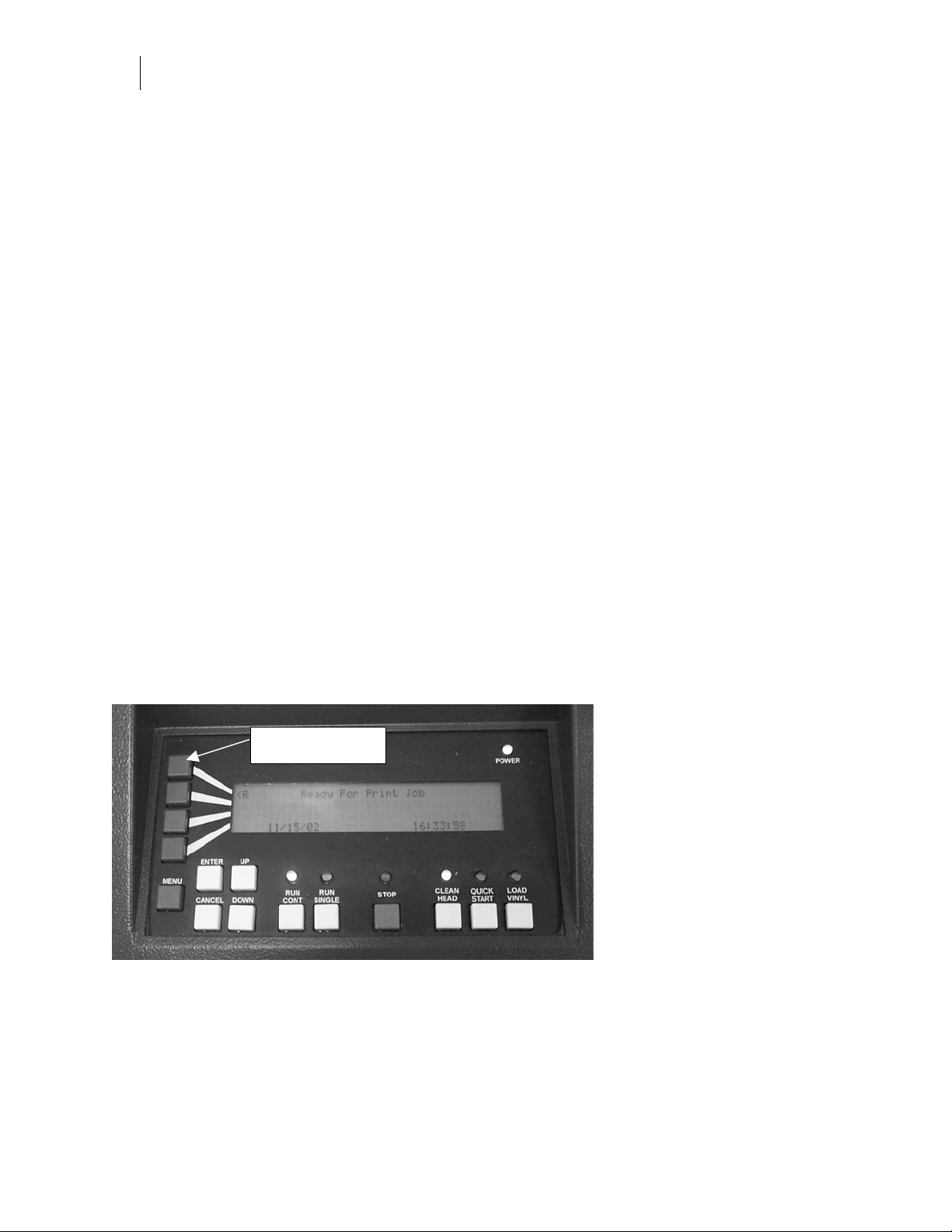
Control panel keys
The illustration below shows the MAXX 2 control panel. The keys and their functions are
discussed in this chapter.
4 Function keys
The control panel is the interface between the user and the printer. The message display
provides information and prompts, while keys provide the ability to control the printer
functions.
The control panel displays up to four lines of a message at one time. The UP and DOWN
buttons scroll messages that are longer than 4 lines. Message lines preceded by the “<” symbol
Page 19

indicate that pressing the key will result in action or display submenus. The lines from the
function keys to the message lines indicate which key to press on the display.
The following chart briefly describes the purpose of the keys.
Name Purpose
Function keys These four keys have functions that change depending on the
menu or message display.
MENU Press this key to display the Main menu.
ENTER Press this key to confirm a selection you make in the menu
mode.
CANCEL Press this key to exit the current menu without making any
menu changes.
UP Press this key to slew vinyl through the printer. It is also used
to scroll through message displays greater than four lines and
to change numeric values.
13
DOWN Press this key to slew vinyl out of the printer. It is also used to
scroll through message displays greater than four lines and to
change numeric values.
RUN CONT In the RUN CONTINUOUS mode, the printer stays online when
a printing job is complete. If more than one job is sent to the
printer, the next job starts automatically if a material change is
not required. Press this key when the RUN CONT indicator light
is on to put the printer into the pause mode (the light blinks).
RUN SINGLE In the RUN SINGLE mode, the printer goes offline when a
printing job is complete. Press this key when the RUN SINGLE
indicator light is on to put the printer into the pause mode (the
light blinks).
STOP Press this key once to pause a job. Press this key twice to
immediately halt printing, terminate the job, and put the
printer offline.
CLEAN HEAD Press this key to initiate the automatic head cleaning
sequence.
QUICK START Press this key to eliminate the automatic substrate alignment
and straightening procedure between jobs. Press and hold this
key for 5 seconds to move the printhead to the left from the
park position and allow you to refill the wiper box.
LOAD VINYL Press this key to raise the vinyl squeegees and open the
magnet bars so you can load material. Press the key again to
lower the vinyl squeegees and close the magnet bars.
Page 20

CHAPTER 3
14
Understanding the MAXX 2 Control Panel
MAXX 2 power up sequence
When the MAXX 2 is turned on it initializes the axes and then displays the firmware version
number followed by the Ready message. Do not press any of the control panel keys when you
first turn on the MAXX 2. Wait until the
Ready to Print Job
message or a prompt is displayed.
Entering menu selections
When the display is showing printer status, such as
Ready to Print Job
, press MENU on the
control panel to open the Main menu. The display is:
< Bay Status
< Job Queue
< Setup
< Service
Message lines preceded by the “<” symbol indicate that pressing the key results in an action or
displays submenus. For example, if you press the function key corresponding to the
< Setup
message line, the display changes to:
< About Printer
< Language
< Units
< Connection
Pressing the function key corresponding to
< Set English Units
< Set Metric Units
< Units
changes the display to:
Pressing the function key for one of the choices activates it.
Starting jobs
Starting jobs is controlled by the RUN CONT and RUN SINGLE keys. When you send a job to
the printer from the GSPPlot program, the lights over the two keys blink alternately. Pressing
either one of the keys starts the printing sequence and the light is on over the pressed key to
indicate the active printing mode.
Run single mode
In the run single mode, the MAXX prints one job and stops (even if more than one job was sent
to the printer). When you press RUN SINGLE, the light over the key is on and the light over the
RUN CONT key is off. When the job is complete, the light goes off if only one job was sent to
the printer. If more than one job was sent, when the job is complete the lights over the two keys
blink alternately to alert you that another job is in the queue for printing. To start the next job,
press either the RUN CONT or the RUN SINGLE key.
Page 21

15
Run continuous mode
In the run continuous mode, the MAXX prints continuously as jobs are sent to it. When you
press RUN CONT, the light over the key is on and the light over the RUN SINGLE key is off.
When all jobs are complete, the light remains on, indicating that when another job is sent, it will
start to print without operator intervention. The printer remains in the run continuous mode
until you pause the printer or change to the run single mode.
Note: You can change the mode while a job is printing. For example, if you start printing in the
run continuous mode and press RUN SINGLE while printing a job, the printer changes to the
run single mode and stops when the job is complete.
Quick Start operation
Note: Be aware that when printing a job longer than 4 feet (1.22 meters), the MAXX 2
performs a precise material straightening sequence. This sequence can take up to three minutes
before printing starts.
Quick Start is a convenient feature when printing multiple jobs that are less than 5 feet (152.4
cm) in length on the same substrate. After aligning the vinyl for the initial job, the Quick Start
feature saves time by eliminating the substrate alignment and straightening procedure on
subsequent jobs. The operator must be present to ensure that the vinyl is properly loaded. Take
care when using Quick Start.
Do not use Quick Start if:
♦ a job is longer than 5 feet (152.4 cm)
♦ the operator is leaving the MAXX 2 unattended while printing multiple jobs of any
length
The QUICK START key enables Quick Start operation. When you press this key so that the
indicator light is on, the following occurs:
♦ the MAXX 2 assumes that the correct vinyl type is loaded and that it is parallel to the
loading alignment line
♦ straightening and alignment is not performed after the initial sequence
♦ the vinyl width and positioning checks are performed
♦ there is no gap between jobs when printing multiple jobs
To deselect Quick Start mode, press the QUICK START key again. Quick Start is also deselected
at start-up or by pressing the RUN SINGLE, RUN CONT, or STOP key when no job is running.
Stopping and restarting jobs
Terminating jobs is a multi-step process. After a job starts printing, press STOP on the control
panel to pause the printing. If you press STOP again, the following display appears:
< Cancel This Job
< Cancel This Job and Advance Substrate
< Continue This Job
Page 22

CHAPTER 3
16
Understanding the MAXX 2 Control Panel
Press the function key adjacent to the action you want to take. When you choose
the job is aborted and the remaining data is cleared from the printer buffer. If you press
This Job
the job is restarted.
Cancel This Job
Continue
Note: If you cancel a job in GQMgr, the substrate will always be advanced. If you cancel a job
using the MAXX keypad, the canceled job will be pulled off the platen only if you choose
This Job and Advance Substrate
.
Cancel
Pausing jobs and restarting a job
Printing may be temporarily stopped at any time while a job is printing. To pause a job, press
the RUN key that is lit to enter the paused mode. The printer completes the swipe it is currently
printing, then unloads the cassette. The RUN CONT and RUN SINGLE lights alternately blink.
The display is
Paused by Operator
Job Name
Foil:
name of foil
Vinyl:
name of vinyl
To restart a job from the paused mode (as indicated by the alternately blinking lights), press
either the RUN CONT or RUN SINGLE key. The job resumes in the mode selected by the key.
Reprinting the last job
When you are in the run single mode, you can reprint (also called replay) the last job you
printed. You can also use this feature to restart a job you aborted. The display message is
< R Job waiting to print
. If you press the function key next to the
< R
symbol, the job automatically
reprints. In the run continuous mode, only the last job in a sequence can be replayed.
Queuing jobs at the MAXX 2 control panel
The Main menu item, <
♦ display a list of all jobs currently in the queue (excluding jobs marked for abort)
♦ determine if a job is available for reprinting (called the replay job)
♦ display detailed information about each queued job
♦ re-position jobs in the queue
♦ delete jobs from the queue
Displaying a list of jobs in the View Job Details
When the Job Queue function key is selected, a list of all the jobs in the queue (not marked for
abort) displays. The queue can hold up to 32 jobs and includes the queue position and job
description (or file name if it is a test or calibration job) for each job. Use the UP and DOWN
keys to scroll through the list.
The most recent job that is started (the job does not have to finish printing) is held in MAXX
memory as a replay job. When in run single mode you can examine a job and if required,
reprint the replay job without resending it from GQ Manager. When a replay job is available, it
displays at the top of the Job Queue, but with the letter
Job Queue
, allows you to:
R
in place of the queue position number.
Page 23

As a new job is printed, it replaces the previous replay job in memory. You can not delete a
replay (
R
) job from the Job Queue.
When in run continuous mode, the replay job is automatically replaced when a new job is
started. At the end of a RUN CONTINUOUS sequence, the last job printed is the replay job.
Note: Any incompletely printed or unprinted jobs in the queue are retained at power-down.
This feature ensures that you will not lose work in the event of a power loss. For partially
printed jobs, the entire job can be reprinted.
To display the job queue
1
Press MENU on the control panel. The display is:
< Bay Status
< Job Queue
< Setup
< Service
17
2
Press the function key for
< Job Queue
. The display for a Job Queue with five jobs is
shown below. Your display will vary based the number of jobs in the queue.
Job Queue (5)
< R Replay Job Description
< Job A Description
< Job B Description
3 Press DOWN or UP to scroll through the queue.
Displaying detailed information about each queued job
Press the function key adjacent to any job listed in the queue and choose View Job Details to
display the job information. This display shows the queue position, the job identification
number (which is assigned by GQMgr), the job (file) name, the first foil that prints, and the
substrate name. If you press the function key for the foil, you get a list of all foils in the job.
To display detailed job information
1
Press the function key next to a job. This display is:
< View Job Details
< Change Queue Position
< Remove Job From Queue
2
Press the function key for
Queue #: 2 Job Id: 17
Job B Description
< Process – Black GCP-712
< Vinyl: White 225 Custom
(not displayed for a replay job or when there is only one job in the queue)
(not displayed for a replay job)
< View Job Details
(if you press this function key, you get a list of all the foils in the job)
. The display is:
3
Press CANCEL to return to the Job Queue.
Page 24

CHAPTER 3
18
Understanding the MAXX 2 Control Panel
Re-positioning a job in the queue
When you change the position of a job in the queue, other jobs are shifted up or down in the
queue as needed. Re-positioning is not available for the replay job or when there are less than
two jobs are in the queue. It is not possible to change the queue position when the job at the
original or new queue position has already begun to print.
To change the position of a job in the queue
1
Press the function key next to a job. This display is:
< View Job Details
< Change Queue Position
< Remove Job From Queue
(not displayed for a replay job or when there is only one job in the queue)
(not displayed for a replay job)
2
Press the function key for
Job B Description
Move From Entry 2 to: 3
Press UP/DN To Adjust
ENTER to save, CANCEL to quit
3
Press UP or DOWN to move the job to a new queue position.
4
Press ENTER to save the new position.
< Change Queue Position
. The display is:
Deleting jobs from the queue
You can delete a job from the queue by using the Remove Job From Queue command. Deleting
a job is not available for the replay job or if a job has already begun to print.
When you select Remove Job From Queue, you must respond to a confirmation message before
the job is marked for deletion. (When viewing the Job Queue from GQ Manager, jobs removed
from the queue are marked as aborted.) Even though a deleted job no longer appears in the
queue on the MAXX 2 display, the job is not removed from the queue until it reaches the first
queue position. Deleted jobs that still reside in the MAXX queue occupy one of the 32 available
queue positions. To immediately remove a job from the queue, move the job to the first queue
position and then delete it.
To delete a job from the queue
1
Press the function key next to a job. This display is:
< View Job Details
< Change Queue Position
< Remove Job From Queue
(not displayed for a replay job or when there is only one job in the queue)
(not displayed for a replay job)
2
Press the function key for
Queue #: 2 Job Id: 17
Job B Description
Remove this job from queue?
Press ENTER if “yes”, CANCEL if “no”
3
Press ENTER to delete the job.
< Remove Job From Queue
. The display is:
Page 25

19
Adjusting the pull distance when slewing material
When pressing the UP or DOWN key, the MAXX 2 slews the material a designated amount. The
default value is 16 inches (40.64 cm). You can temporarily adjust the amount of material that is
pulled across the platen when slewing.
To temporarily adjust the pull distance amount
1
Press and hold the UP or DOWN key on the MAXX 2 control panel. When pressing the
UP key the display is:
Enter Pull Distance
16
When pressing the DOWN key the display is:
Enter Pull Distance
-16
2
Press UP to increase the pull distance or DOWN to decrease the pull distance. Press
ENTER to accept the new value or CANCEL to exit.
3
Press the UP or DOWN key to slew the material the distance entered. The pull
distance then resets to the default value of 16 inches and –16 inches (40.64 cm to
–40.64 cm).
Updating the MAXX 2 firmware
Occasionally GSP will update the firmware in your GERBER MAXX 2 to a new revision level.
Before updating the firmware using GQ Manager, you must set the MAXX 2 to accept a system
update.
Note: Before installing the MAXX 2 firmware, it is important to clean out the
c:\Windows\temp directory so that there is space to enable you to back up files before
installing the new firmware.
To update the MAXX 2 firmware
1
On the MAXX 2 keypad press
System ready for update…
Press CANCEL or MENU to exit:
2
On the computer attached to the MAXX 2 click Start > Programs > OMEGA > GQMgr
to open the GQ Mgr dialog box.
3
Right click on the MAXX icon to access Properties.
4
Click Properties to open the Properties for Gerber MAXX dialog box.
Menu > Service > System Update
. The display shows:
Page 26

CHAPTER 3
20
Understanding the MAXX 2 Control Panel
5
Click Batch to open the Open GSP MAXX Batch File dialog box.
6
Browse the Look in drop down list to find your CD drive, then open it.
7
Click Firmware > MAXX > Backup XX.mxb. The current system files backup to the
temp directory.
8
Click Build XX.mxb. The firmware installs. As the firmware is installing, messages will
automatically scroll through the Properties for Gerber MAXX dialog box. When
finished the following message is displayed:
MAXX FILES TRANSFERRED
CYCLE POWER ON MAXX TO
COMPLETE FIRMWARE UPDATE
9
After installing the new firmware and before sending a job to the MAXX 2, turn the
MAXX 2 off for at least 10 seconds before restarting the machine.
Page 27

Chapter 4:
MAXX 2 Care and Cleaning
Extensive in-house and field testing reveal that proper cleaning of the MAXX 2 and the
substrates are essential to maintaining good print quality. The following sections provide
comprehensive inspection, cleaning, and foil care instructions.
CAUTION: When cleaning the MAXX 2 (or any time you have the cover of the
MAXX 2 open), you increase the chance of contaminates such as sand or dirt
adhering to the head cleaning pad or platen. Inspect these areas carefully after
cleaning to guard against possible damage.
Recommended MAXX 2 cleaning materials
21
The recommended cleaning materials are:
♦ rubber gloves (strongly recommended)
♦ pink ThermApprove printhead cleaning film, Gerber part number P72966C
♦ ThermApprove printhead cleaning kit, Gerber part number P66530B
♦ a clean, lint-free cloth
♦ 99 percent isopropyl alcohol
♦ tack cloth (commercially available from most hardware stores)
♦ glass cleaner
♦ 3-IN-ONE machine oil
♦ Chemtronics Ultrajet 2000 (or equivalent) compressed air, ultra-filtered,
non-residue dust remover
Daily cleaning procedures
Daily cleaning of the MAXX 2 is strongly recommended. Everyday you should:
♦ Vacuum the exterior of the MAXX 2.
♦ Clean the magnet bars and squeegees.
♦ Clean the edge sensor strip.
♦ Clean the platen.
♦ Inspect and if necessary, refill the wiper box.
♦ Clean the ways, lead screw, and ball screws.
♦ Clean the material catching baskets.
Page 28

CHAPTER 4
22
MAXX 2 Care and Cleaning
Cleaning the vinyl squeegees and magnet bars
Turn on the printer and press LOAD VINYL on the control panel to raise the front and rear
vinyl squeegees. Remove any material loaded in the printer. Use a wet alcohol printhead
cleaning pad to clean the squeegees. Fold it in half and wrap it around the squeegee, then wipe
the entire length of the squeegee. The squeegee is clean when you re-wipe the squeegee and the
pad still looks clean. You may refresh the pad with 99 percent isopropyl alcohol if it becomes
dry during cleaning.
Note: Isopropyl alcohol may discolor the squeegees over time. Discoloring does not affect the
operation of the squeegee.
Platen
Magnet bar
Tilt the cassette rack out of the front of the printer to allow access to the magnet bars and wipe
them clean with a lint-free cloth moistened with glass cleaner. Pay special attention to the small
slot between the top and bottom of the magnet bar. Be careful to not get the cleaning cloth
trapped under the magnet bar. Check the magnet bars for pieces of vinyl that may have gotten
stuck to them.
An additional way to clean the magnet bar and keeper plate is tilt the foil cassettes out to gain
access to the magnet bar. Remove the pins at each end of the magnet bar and slide the keeper
plate out. This also allows more room to clean under the magnet bar. Be careful to not bend the
keeper plate. Reinstall the keeper plate in exactly the same orientation with the slightly rounded
edges facing up. Allow the area to air dry before loading material. If you are not loading
material at this time, press LOAD VINYL to lower the vinyl squeegees.
Tip: It is a good idea to wipe the material tray with the alcohol-moistened cloth while you are
cleaning the squeegees and magnet bars. Occasionally, adhesive may build up on the tray from
the material passing over it.
Page 29

Cleaning the edge sensor strip
The edge sensor strip is located behind the back cover panel above the table.
To clean the edge sensor strip
1
Unload any material from the printer.
2
Move the rear material catching basket away from the back of the printer.
3
Remove the three screws across the top of the back cover panel so that the cover can be
lowered on its hinges.
4
Locate the edge sensor strip. It is a very dark strip (much darker than the surrounding
black surface and has a matte finish) just inside of the rear squeegee.
5
Use a compressed air, ultra-filtered, non-residue dust remover (such as Chemtronics
Ultrajet 2000 or equivalent) to quickly spray the entire length of the edge sensor strip
from left to right.
6
Vacuum away any dislodged debris.
7
Secure the back cover panel to the printer with the three screws removed at step 3 and
replace the material catching baskets.
23
Cleaning the platen
CAUTION: When cleaning the platen as described in the next paragraphs, do not
wipe or clean the black edge sensor notch with alcohol or cleaning solvents that will
damage or change the paint color. It is important to keep this area free of dust, lint,
and dirt.
Moisten a clean, lint-free cloth with 99 percent isopropyl alcohol and wipe the platen to remove
any dirt, debris, or adhesive. Be sure to check the platen for pieces of vinyl that may have gotten
stuck to it. Allow to air dry. Wipe the platen with a tack cloth to remove any contaminates that
may interfere with printing and damage the printhead.
An edge sensor notch strip is located at the center of the platen on the left side. It is a notch
approximately 2" (50.8 mm) long and 1/2" (12.7 mm) wide cut into the platen and is painted
black. Clean the edge sensor notch strip by quickly spraying in the notch with a compressed air,
ultra-filtered, non-residue dust remover such as Chemtronics Ultrajet 2000.
Page 30

CHAPTER 4
24
MAXX 2 Care and Cleaning
Inspecting and refilling the wiper box
CAUTION: When inspecting the wiper box as described in the next paragraph,
verify that there is cleaning film in the wiper box and that all four corners of the
film strips are under the corners of the wiper box. If the film is not completely
seated and under the corners, equipment damage may result.
Inspect the cleaning film in the head wiper box and be certain to keep the head wiper box filled.
Do not over-fill the box; one full package (100) of ThermApprove printhead cleaning film is
sufficient. Load the package into the head wiper box with the dull (and slightly abrasive) side
facing up toward the printhead. If the wiper box is nearly empty, it may contain small metal
chips, which could damage the printhead during the head cleaning cycle. Refill the wiper box
before it is completely empty and inspect for any contaminates on the surface, which could
damage the printhead.
If you cannot easily fit your hand under the printhead to load the cleaning film in the head
wiper box, you can move the printhead out of the way and park it. On the MAXX 2 control
panel, press and hold the Quick Start key for five seconds. The printhead moves to the left and
stops and the display is
printhead automatically relocates to the proper position before printing the job
Ready for print job
. After you load more cleaning film, just send a job. The
Cleaning the ways, lead screw, and ball screws
Note: To clean the ways and ball screws, remove the left and back covers and open the right
cover.
The MAXX 2 has six ways: two X ways for moving the magnet bars; two Y ways for the
printhead carriage assembly; and two Z ways in the printhead carriage for raising and lowering
the printhead. There is a Z lead screw that raises and lowers the printhead and three ball screws
for the X and Y axis.
Smooth operation of moving parts depend on the ways and lead screws being clean and free of
debris. Use a clean, lint-free cloth to clean the ways, lead screw, and ball screws. Occasionally −
every two or three months − lightly oil the ways and ball screws with light machine oil such as
3-IN-ONE.
Cleaning the material catching baskets
Use a clean, dry, lint-free cloth to wipe the metal surfaces and the straps of the material catching
baskets.
Page 31

25
The importance of cleaning the printhead
Proper cleaning of the MAXX 2 printhead is extremely important for maintaining consistent
print quality. The following photographs show a print made before the printhead was cleaned.
Note the raggedness at the start of the print and the visible seaming in the print.
The dirty printhead contributes to a ragged application of the foil to the vinyl. Seaming is
evident and caused by dirt at the extreme ends of the printhead. In the close-up view below, the
ragged start and seaming are clearly visible.
Seaming Ragged start
Page 32

CHAPTER 4
26
MAXX 2 Care and Cleaning
The following photographs show the same areas after cleaning the printhead and reprinting the
job. The only change made to the MAXX 2 was the cleaning procedure performed according to
the instructions in this document. This should be ample evidence of the importance of cleaning
the printhead, especially the extreme ends.
The circles in these photographs show the exact same areas after cleaning the printhead and
reprinting the job. Note that the seams are now invisible and there is no ragged start to the
printing.
Page 33

27
Automatic head cleaning
The MAXX 2 performs an automatic head cleaning by wiping the printhead across the cleaning
film in the wiper box before printing each job. While the cleaning occurs, the light above the
CLEAN HEAD key flashes. You have the ability to manually initiate the sequence by pressing
the CLEAN HEAD key (even in the middle of printing a job).
The MAXX 2 counts the number of cleanings, and after a preset number, displays
detected message
change head cleaning pad.
. When you press the function key to view the error, the display is
Open the right side cover and remove the top cleaning pad (pink film)
Error(s)
Reminder to
in the head wiper box.
CAUTION: After you remove the top cleaning pad, verify that there are pads in the
wiper box and that all four corners of the fresh pad are under the corners of the
wiper box. If the cleaning film is not completely seated and under the corners,
equipment damage may result. Check that there are no small bits of dirt or metal
chips on the cleaning film. These small particles of dirt of metal chips can cause
serious damage to the printhead.
Even though the MAXX 2 automatically cleans the printhead, you should still manually clean
the printhead every day. See the following instructions.
Manually cleaning the printhead
NOTE: Because head cleaning is automatic, the frequency of manual cleaning with the pink
ThermApprove cleaning film is very low. Cleaning with an alcohol pad should be done more
often
procedures for cleaning with both the pink cleaning film and the alcohol pad. The use of heavily
pigmented foil such as white may require more frequent cleaning.
up to several times per day if the MAXX 2 is printing all day. Use the following
−
CAUTION: When cleaning the printhead (or any time you have the cover of the
MAXX 2 open), you increase the chance of contaminates such as sand or dirt
adhering to the cleaning pad or platen. Inspect these areas carefully after cleaning to
guard against possible printhead damage.
Before cleaning the printhead, the printhead carriage must be parked (stopped at the far right of
the MAXX 2). Open the right end cover to see the printhead carriage and printhead.
Page 34

CHAPTER 4
p
28
MAXX 2 Care and Cleaning
End of the
rinthead
The photographs below are close-up views of the printhead. The photograph on the left shows
the printhead mounted on the printhead carriage. The photograph on the right (printhead
removed from the MAXX 2 for identification purposes) shows the parts of the printhead.
Peel bar
Bead or print
element
Green strip
between bead
and insulation
Black insulation
Peel bar Bead or print
element area
Circuit card
Page 35

29
Cleaning the printhead is slightly awkward because it is difficult to see where you are cleaning.
You can get down on your knees so that you are looking up at the bottom of the printhead
carriage or you can reach under the bottom of the printhead from the top as shown. In this
photograph, note that the cleaning film is between the printhead elements and the fingers so
that the skin is not touching the elements. Gerber strongly recommends that you wear rubber
gloves when cleaning the printhead.
Printhead
Pink cleaning film
Cleaning the printhead is a two-step operation. The first step is to clean the peel bar and
printhead elements using the pink cleaning film. The second step is to remove dirt buildup on
the head using the pre-moistened alcohol pad from the cleaning kit. It is very important to
clean the entire width of the printhead. The worst buildup and contamination normally
occur at the ends of the peel bar and printhead element.
Note: If you are cleaning the printhead after a foil break, visually inspect the printhead and
elements very closely to make certain that foil has not fused to the printhead. Extra cleaning
may be required if fusing has taken place.
To manually clean the printhead
CAUTION: When cleaning the printhead, it is very important that your fingers do
not touch the printhead element. Oils and salt on your skin will damage the
printhead. Be certain to keep the printhead cleaning film and the pre-moistened
alcohol pad between your fingers and the printhead. We strongly suggest using
rubber gloves to prevent your skin from touching the printhead, although the
gloves are not a requirement as long as your skin does not contact the printhead.
1
Rub the front and bottom of the peel bar with the dull, abrasive side of the pink
cleaning film. Be certain to rub the entire width of the peel bar all the way out to each
edge. Use about one pound of pressure when rubbing and rub the width for
approximately 10 strokes.
Page 36

CHAPTER 4
30
MAXX 2 Care and Cleaning
2
Rub the printhead element strip or bead with the dull, abrasive side of the pink
cleaning film. Be certain to rub the entire width of the bead all the way out to each
edge. Use about one pound of pressure when rubbing and rub the width for
approximately 10 strokes.
Tip: Save the used pink cleaning film for cleaning the cassette. Do not use it again to clean the
printhead.
3
Using the pre-moistened alcohol pad from the cleaning kit, rub the peel bar, printhead
elements, the green strip area between the bead and the insulation. Do not clean the
circuit card. Rub the entire width all the way out to each edge approximately 10
strokes. You may refresh the alcohol pad with 99 percent isopropyl alcohol if the pad
becomes dry when cleaning.
Peel bar
Bead or print
element
Green strip
between bead
and insulation
Black insulation
Circuit card
Page 37

31
Cleaning foil cassettes
Clean the foil cassette each time before loading it with foil. The following photographs show the
major areas to clean.
Contact
strip
roller bar right bar right roller
bar roller bar roller bar bar
Left Squeegee Lower Squeegee Lower Right
Contact
strip
CAUTION: When cleaning the cassette with 99 percent isopropyl alcohol, be
certain that the cassette parts are completely dry before loading the cassette with
foil. Wet alcohol could damage the foil.
To clean the cassette
1
Rub the squeegee bar with the dull, abrasive side of new or used pink cleaning film. Be
certain to rub the entire width of the squeegee bar all the way out to each edge. As
shown in the following photograph, backcoat from the foil typically builds up at the
far edges of the squeegee bar. Use about one pound of pressure when rubbing and rub
the width for approximately 10 strokes.
Usual area of backcoat buildup
Squeegee bar
Usual area of backcoat buildup
Page 38

CHAPTER 4
32
MAXX 2 Care and Cleaning
2
Moisten a clean, lint-free cloth with 99 percent isopropyl alcohol and wipe the roller
bars, squeegee bar, and the contact strips. Use the moistened cloth to wipe the metal
parts of the removable cover.
3
If there is no foil in the cassette, quickly spray the interior of the cassette with a
compressed air, ultra-filtered, non-residue dust remover (such as Chemtronics Ultrajet
2000 or equivalent).
Tip: When cleaning the cassette with the alcohol, it is a good time to wipe the MAXX 2 foil bay
contact strips in the cassette rack and on the cassette to ensure good clean contact
between the contact strips on the bay stops and the cassettes.
Page 39

Chapter 5:
Printing Jobs
This chapter describes the process of printing jobs on the GERBER MAXX 2. It covers the
following topics.
♦ Setting up and sending the job
♦ Determining the status of each bay
♦ Printing the job
♦ Printing test jobs
Setting up and sending the job
33
Jobs are set up and sent to the MAXX 2 in the GSPPlot program. The MAXX 2 is capable of
printing any job file that can be opened in the GSPPlot program of OMEGA 1.56 or higher or
that has been rendered and saved as an SPL file. For a complete list of usable file types, click on
the down arrow beside the Files of type list box in the GSPPlot Open dialog box.
After you open a job in GSPPlot, you can use all the features of the program to set up the job
(such as rotate, panel, and repeat, for example). To use the GSPPlot program, refer to the
GSPPlot Help system.
After the job is set up, click on the print button to send the job to the MAXX 2.
Determining the status of each bay
The Bay Status display shows you the name of the foil and amount of foil in each bay.
To view the Bay Status
1
Press MENU to display the Main menu.
< Bay Status
< Job Queue
< Setup
< Service
2
Press the function key for
bays. Following is an example of a typical display.
< Bay Status
. The display shows the status of the first three
Bay Inches Description
1 empty
< 2 4759 PROCESS CYAN GCP-707
< 3 2590 PROCESS YELLOW GCP 705
Page 40

CHAPTER 5
34
Printing Jobs
3
Press DOWN key to view the status of the next three bays. Press UP to view previous
lines of information. To return to the Main menu, press CANCEL on the control panel.
Reducing the recorded amount of foil in a cassette
If you have manually advanced some foil, to move past dirt or a tear in the foil, you should
reduce the amount remaining on the roll so that the recorded and displayed amount is accurate.
To reduce the recorded amount of foil in a cassette
1
Press MENU to display the Main menu.
< Bay Status
< Job Queue
< Setup
< Service
2
Press the function key for
< Bay Status
. The display shows the status of the bays.
Following is a typical example.
Bay Inches Description
1 empty
< 2 4759 PROCESS CYAN GCP-707
< 3 2590 PROCESS YELLOW GCP 705
3
Press the function key for the foil you want to reduce. In this example, we want to
reduce the amount of Process Cyan. The display is:
Reduce Foil Remaining, Bay 2
4759 inches
4
Estimate the number of inches of foil you advanced, then press DOWN to reduce the
amount shown in the display. Press ENTER to accept the new value.
Note: If you accidentally decrease the value too much, the UP key allows you to increase the
amount back to the starting value, but no greater.
Printing the job
When the printer is ready for a job, the display is
RUN CONT and RUN SINGLE keys blink.
When you send a job, it automatically starts printing if the printer is in the RUN CONT or RUN
SINGLE mode. If it is not in a RUN mode, the display at the top level is:
Ready For Print Job
and the lights above the
Job Waiting To Print
job name
< Foil:
name of foil (press this key to get details of foils in the job)
< Vinyl:
name of vinyl (press this key to get details of the vinyl in the job)
The first thing that happens before each job, whether in RUN SINGLE or RUN CONT, is that
the printer aligns the printhead to the left edge of the material. The display is:
Adjusting Vinyl…
Note: If the MAXX 2 is in Quick Start mode, it only adjusts the vinyl for the first job sent to
the MAXX 2. You will not see the
Adjusting Vinyl…
message for subsequent jobs.
Page 41

When adjustment is complete, the display is:
Printing
job name
< Foil:
name of foil
< Vinyl:
name of vinyl
Printing continues until:
♦ the job is complete in the RUN SINGLE mode. If more jobs are waiting to be printed,
the RUN CONT and RUN SINGLE lights alternately blink.
♦ all jobs are complete in the RUN CONT mode. The light over the RUN CONT key
remains on to indicate that the printing sequence will start automatically when more
jobs are sent.
♦ a condition requiring operator intervention is encountered such as the printer runs out
of foil or vinyl or the vinyl required is different than the last job printed. In this case,
the printer pauses and displays a prompt message to tell you what to do.
Tip: Refer to the chapter “Understanding Messages” on page 43 for a list of messages, what
each means, and your response to the message.
35
Viewing foil and material information for the job
Before or after you start printing, you can check the foil and vinyl status by pressing the
function key opposite the
< Foil:
name of foil
When viewing foil details, the display shows the foils needed in the job, the amount of foil
loaded in the cassette, and the amount of foil that is required for the job. When viewing material
details, the display shows the design width of the job, and the actual width and length of
material required.
To view the foils information for the job
1
From the Main menu press
Job Queue (n)
< 1 Job name
< 2 Job name
< 4 Job name
< Job Queue
2 Press the function key next to a job. This display is:
< View Job Details
< Change Queue Position
< Remove Job From Queue
3
Press the function key for < View Job Details. The an example of a typical display is:
Queue #: 2 Job Id: 17
Job Description
< Process yellow GCP-706
< Vinyl: White 225 Custom
(not displayed for a replay job or when there is only one job in the queue)
(not displayed for a replay job)
(if you press this function key, you get a list of all the foils in the job)
< Vinyl:
or
. The display is:
name of vinyl
line in the display.
4
Press the function key for the foil. An example of a typical display is:
Foils needed this job (1 of 4)
Process yellow GCP-706
60 in. loaded, Bay 1
48 in. required
Page 42

CHAPTER 5
36
Printing Jobs
5
Press the DOWN arrow to scroll through the foils required for the job. An example of a
typical display is:
Foils needed this job: (2 of 4)
Process magenta GCP-773
40 in. loaded, Bay 2
48 in. required – load more
6
In this case, there is not enough Process Magenta foil to complete the job. You can
either pause the printer now and load the foil, or press RUN to continue the job. If you
let the job continue, when the process magenta foil color reaches the low foil threshold
value the MAXX 2 pauses and displays:
Foil Low, Bay 2
or
Foil Very Low, Bay 2
7
Press RUN to continue printing, or replace the foil in the cassette and then press RUN.
To view the material information for the job
1
From the Main menu press
Job Queue (n)
< 1 Job name
< 2 Job name
< 4 Job name
< Job Queue
. The display is:
2 Press the function key next to a job. This display is:
< View Job Details
< Change Queue Position
< Remove Job From Queue
3 Press the function key for
Queue #: 2 Job Id: 17
Job Description
< Process yellow GCP-706
< Vinyl: White 225 Custom
4
Press the function key for the vinyl. An example of the display is:
Job Vinyl Information
Expected Roll Size 36.0 inches
Job Width (y) 14.7 inches
Job Length (x) 155.7 inches
5
To exit any of these displays, press CANCEL.
(not displayed for a replay job or when there is only one job in the queue)
(not displayed for a replay job)
< View Job Details
(if you press this function key, you get a list of all the foils in the job)
. The display is:
Tip: When printing in the run continuous mode, try to group jobs by material and foil colors,
then make sure that the foil colors for all jobs are loaded in the cassette rack. This allows the
MAXX 2 to print all the jobs in an unattended mode without pausing. To check the list of foils
loaded in the cassette rack, check Bay Status as described in “Determining the status of
each bay” on page 33.
Page 43

Printing test jobs
The GERBER MAXX 2 includes a number of test jobs in the Service > Run Test Job menu. See
the descriptions below for detailed explanations of each job.
Test Job Foils Used Job Description
BLACK50.RAW Process Black Used by an installation technician to calibrate the
MAXX 2.
BLACK75.RAW Process Black Used by an installation technician to calibrate the
MAXX 2.
CYAN50.RAW Process Cyan Used by a technician for density calibration.
CYAN75.RAW Process Cyan Used by a technician to calibrate the MAXX 2.
MAGTA50.RAW Process Magenta Used by a technician to calibrate the MAXX 2.
MAGTA75.RAW Process Magenta Used by a technician to calibrate the MAXX 2.
EIFFEL.RAW 4-color Process Used by an installation technician to calibrate the
MAXX 2.
37
MAXXLOGO.RAW 4-color Process Used by an installation technician to verify MAXX 2
operation.
PREMIUM.RAW Ruby Red
Spot Black
RUBYPULL.RAW Ruby Red Used by an installation technician to check seam
STARTUP.RAW Process Yellow
Process Black
BREAK.RAW Process Black Used by a technician to check calibration of the MAXX
LPISHP.RAW Process Black Reference chart of available halftone types for shape
LPISHPO.RAW Process Black Reference chart of the resulting optimized halftone
Used by an installation technician to check seam
overlap on spot colors.
overlap on spot colors.
Used by a technician to check calibration of the MAXX
2 after installing a new printhead.
2 after installing a new printhead.
fills. Includes blocks filled with 10% to 100% black
tint in 10% increments in the following halftone types
GerberTone Fine, GerberTone Long, GerberTone,
Classical Dot 14, 18, 26, 42, 52, and 70 LPI.
for
100% black tint in 10% increments. Although labeled
Optimized GerberTone Fine, Optimized GerberTone
Long, or Optimized GerberTone, the halftones are
identical – Optimized GerberTone MAXX.
fills. Includes blocks filled with 10% to
shape
LPIBM.RAW Process Black
Reference chart of available halftone types for
fills. Includes blocks filled with 10% to 100% black
tint in 10% increments in the following halftone types
GerberTone Photo, GerberTone Artwork, Stochastic,
Classical Dot 14, 18, 26, 42, 52, and 70 LPI.
image
Page 44

CHAPTER 5
38
Printing Jobs
LPIPROC.RAW 4-color Process Reference chart of four images filled with the
following halftone types: GerberTone, Classical Dot
70, 42 and 26 LPI. Top section of each image is a
multicolor linear fill to illustrate color banding that
may occur with different halftone types. Bottom
section of the image is a four color photo to illustrate
image details and range of color.
LPIPROCO.RAW 4-color Process Example of the same four color image used in
LPIPROC.RAW after being optimized through GSPPlot.
The halftone type is Optimized GerberTone MAXX.
Top section of the image is a multicolor linear fill to
illustrate color banding. Bottom section of the image
is a four color photo to illustrate image details and
range of color. See
MAXX 2
for more detailed explanations on halftones.
OMEGA Tips for the GERBER
Page 45

39
Chapter 6:
Modifying MAXX 2 Print Settings
Your MAXX 2 is optimized at the factory to produce high quality prints. If you suspect that
your MAXX 2 is out of calibration, you can print several calibration check prints that are
resident in the MAXX 2. You can also fine tune printhead settings for individual materials by
modifying Print Darkness or Seam Adjust. Take care when adjusting factory default settings. If
you have questions about your MAXX 2 print settings, contact Gerber Field Service.
Printing the Pull Out or Pull Back Check prints
The Pull Out or Pull Back check prints are designed to assist a Gerber technician in determining
if your MAXX 2 requires adjustment. The Pull Out and Pull Back Check prints must be printed
on 225 white vinyl only. Using a different substrate may provide erroneous results. After
printing the check prints, contact Gerber Field Service for assistance.
To print the Pull Out or Pull Back Check prints
1
Load a roll of 225 white vinyl in the MAXX 2.
2
Press MENU on the control panel. The display is:
< Bay Status
< Job Queue
< Setup
< Service
3
Press the function key for
< Run Test Job
< Calibration
< System Update
4
Press the function key for
< Calibrate Material Pull
< Calibrate Print
5
Press the function key for
< Print Pull Out Check
< Print Pull Back Check
< Print Long Pull Back Check
6
Press the function key for calibration check print that you want to print. The display
< Service
< Calibration
< Calibrate Material
changes to:
. The display is:
. The display is:
. The display is:
Busy Printing Calibration Image…
7
When the job is complete, contact Gerber Field Service for instructions.
Page 46

CHAPTER 6
40
Modifying MAXX 2 Print Settings
Modifying the Darkness Adjust setting
If you think the printing of a job appears noticeably light or dark or you are having adhesion
problems such as small voids or speckles, you should first clean the vinyl and the printhead,
and then reprint the job. If the print is still unacceptable, you can adjust its appearance by
changing the Darkness Adjust.
Darkness is factory set for an individual printhead. Take care when adjusting the settings. Any
adjustments made to the settings are saved with the specific vinyl family and are used with all
subsequent jobs that use the same vinyl. Different vinyl surfaces (smooth/rough) may require
different settings to achieve optimal adhesion.
The Darkness setting alters the amount of energy used to apply the foil to the substrate and
determines how opaque the color appears. When adjusting Darkness, the new setting applies to
the entire printhead and affects the whole swipe. The settings are vinyl-specific, so be sure you
have the correct vinyl loaded in the GERBER MAXX 2.
To assist you in determining the correct setting for Darkness for a specific substrate (such as
225) you can print a Darkness Adjust Sample. This print consists of a Process Yellow swipe
overprinted with Process Black blocks at five different Darkness settings: +4, +2, 0, -2, and –4.
Print this sample and use it as a reference to determine the optimal Darkness setting for that
substrate.
Tip: Depending on the job, the change in Darkness may be subtle. After altering settings,
reprint the job and compare the new print to the original print to correctly evaluate the
results.
To print the Darkness Adjust Sample
1
On the control panel, press MENU >
Service > Calibration
Calibrate Print
>
. Scroll through
the list of vinyls until you find the proper vinyl, then press the corresponding function
key. The display is:
vinyl (such as 225)
< Seam Adjust
< Darkness Adjust
2
Press the <
< Print Darkness Adjust Sample
< Change Darkness Adjust
3
Press the
Darkness Adjust
< Print Darkness Adjust Sample
function key. The display is:
function key to print the Darkness Adjust
Sample. The MAXX 2 prints a solid yellow swipe overprinted with five blocks of
process black, each at a different darkness setting: +4, +2, 0, -2, and –4.
4
Examine the Darkness Adjust Sample print, especially around the edges of the black
blocks. Make note the best darkness setting for that substrate. You will change the
Darkness setting in the next procedure.
Page 47

To change the Darkness settings
41
1
On the control panel, press MENU >
Service > Calibration
Calibrate Print
>
. Scroll through
the list of vinyls until you find the proper vinyl, then press the corresponding function
key. The display is:
vinyl (such as 225)
< Seam Adjust
< Darkness Adjust
2
Press the <
< Print Darkness Adjust Sample
< Change Darkness Adjust
3
Press the
Darkness: 0
lighter [- - - - - X - - - - -] darker
4
To adjust the Darkness, press the UP key for darker or DOWN key for lighter. Adjust
Darkness Adjust
< Change Darkness Adjust
function key. The display is:
function key. The display is:
the Darkness the amount determined when examining the Darkness Adjust Sample
print and then press ENTER.
5
Reprint your job and compare it to the original print. Depending on the job, the change
in darkness may be subtle. If the results are acceptable, you are done. If the job
requires additional adjustment you can alter the Darkness setting again. If the prints
are still not acceptable after the second adjustment call Gerber Field Service.
Modifying the Seam Adjust setting
If you notice that a print has gaps or obvious overlaps between swipes, you can modify the
Seam Adjust setting. Any adjustments made to the settings are saved with the specific vinyl
family and are used with all subsequent jobs that use the same vinyl. Be sure to have the correct
vinyl loaded in the MAXX 2 when printing.
To assist you in determining the correct setting for Seam Adjust for a specific substrate (such as
225) you can print a Seam Adjust Sample. This print consists of process cyan blocks with five
different overlap settings: +4, +2, 0, -2, and –4. Print this sample and use it as a reference to
determine the optimal Seam Adjust setting for that substrate.
To print the Seam Adjust Sample
1
On the control panel, press MENU >
Service > Calibration
the list of vinyls until you find the proper vinyl, then press the corresponding function
key. The display is:
vinyl (such as 225)
< Seam Adjust
< Darkness Adjust
2
Press the
< Print Seam Adjust Sample
< Change Seam Adjust
< Seam Adjust
function key. The display is:
Calibrate Print
>
. Scroll through
3
Press Print Seam Adjust Sample to print the reference job. The MAXX 2 prints process
cyan blocks with five different seam overlap settings: +4, +2, 0,-2, and -4. Examine the
Page 48

CHAPTER 6
42
Modifying MAXX 2 Print Settings
print and make note of the setting that provides the best overlap. You will change the
Seam Adjust setting in the next procedure.
Note: As the MAXX 2 prints the Seam Adjust Sample will notice that the printer picks up and
drops off the process cyan cassette a number of times. These printer actions are normal and are
required to properly print the sample.
To change the Seam Adjust settings
1
On the control panel, press MENU >
Service > Calibration
Calibrate Print
>
. Scroll through
the list of vinyls until you find the proper vinyl, then press the corresponding function
key. The display is:
vinyl (such as 225)
< Seam Adjust
< Darkness Adjust
2
Press the
< Print Seam Adjust Sample
< Change Seam Adjust
3
Press the
Seam Adjust: 0
less [- - - - - X - - - - -] more
4
Change the Seam Adjust setting to the overlap setting chosen when examining the
< Seam Adjust
< Change Seam Adjust
function key. The display is:
function key. The display is:
Seam Adjust Sample. Press the UP key to increase the overlap or the DOWN key to
decrease the overlap, and then press ENTER.
5
Reprint your job and compare it to the original print. If the results are acceptable, you
are done. If the job requires additional adjustment you can alter the Seam Adjust
setting again. If the prints are still not acceptable call Gerber Field Service.
Page 49

43
Chapter 7:
Understanding Messages
The MAXX 2 control pad message display provides status information and prompts during the
printing sequence. In most cases, the information and prompts are self-explanatory. This
chapter contains a list of messages you may see while operating the MAXX 2. The messages
may appear on lines 1, 2, 3, or 4 of the MAXX 2 display. This chapter divides the messages into
Status Messages and Error Messages. Each list is arranged alphabetically.
Note: If the suggested corrective action does not solve a problem, or if you see a message you do
not understand, please contact your distributor or Gerber Field Service.
Status messages
Status messages can be divided into two categories:
♦ information (abbreviated in the following table as I)
♦ prompts which require action (abbreviated in the following table as
Message Type Comment/Action
A-axis Failure P/A May display at power up when A-axis does not initialize properly.
Check for obstruction and press RUN CONT or RUN SINGLE to
attempt to correct the failure.
Adjusting Vinyl… I Appears after RUN CONT or RUN SINGLE is pressed and before
printing starts.
Adjusting Voltage… I May appear before a swipe as the MAXX 2 automatically adjusts
voltage.
Busy Printing Calibration
Image
Canceled by operator I Appears if you stop a test job.
Cassette Jam Error P/A Check all the bays and make sure the cassettes are properly seated
Check Vinyl Loop P/A Vinyl has run out or there is no loop in the material catching basket.
I Printing a calibration test print.
in the rack; press RUN to try to clear the error message.
Replace vinyl or check for obstructions.
P/A
)
Checking Bays… I Appears when < Bay Status is pressed (followed by the contents of
each bay).
Clear Path to Proceed P/A Check the cassettes in the bays to make sure that they are not
sticking out in the path of the printhead carriage.
Page 50

CHAPTER 7
44
Understanding Messages
Message Type Comment/Action
Close All Bays to Proceed P/A A cassette bay is open. Close the bay.
Close Cover(s) to
Proceed
Cooling Print Head… I Printhead temperature exceeds the range; this message clears when
Cycle Printer Power
Off/On
Detected vinyl too small P/A Appears if the vinyl width is too small for the job dimensions; reload
End of Vinyl Error P/A The vinyl has run out. Replace vinyl and reprint job
Enter Pull Distance P/A Appears if you press and hold the UP or DOWN key; use the UP and
Error Setting Voltage I May occur during power up. Reboot system. If message continues,
Error: - Queue Full I The Job Queue is full. The MAXX 2 can store up to 32 jobs. See
Foil Low, Bay X P/A Displayed prior to loading the cassette. There is between 2% and
Foil Very Low, Bay X P/A Displayed prior to printing a swipe. There is less than 0.1% of the
P/A A cover is open. Close the cover.
printhead temperature is correct.
P/A An unrecoverable error has occurred during printing. Turn the MAXX
2 off and on.
correct vinyl.
DOWN keys to change the amount of vinyl pulled across the platen
when slewing; the default is 16".
call Gerber Field Service.
“Deleting jobs from the queue” on page 18.
7% of the length of a full roll of foil in the cassette and the amount
remaining is less than required for the job. Press RUN to continue or
replace the foil in the cassette and then press RUN.
length of a full roll of foil in the cassette. Press RUN to continue or
replace the foil in the cassette and then press RUN.
Foil Out, Bay X P/A The cassette in Bay X is out of foil. The MAXX 2 is paused. Replace
the foil in the cassette and press RUN to continue.
Foil Broken, Bay X P/A The foil in Bay X is broken. The MAXX 2 is paused. Repair or replace
the foil in the cassette and press RUN to continue.
Initializing… I Appears during power up.
Job Ready
Job Refused – Host
Submit Active
Job Waiting to Print I Appears after a job is sent and before RUN is pressed.
Load More! P/A Appears if you press the function key for foil after a job is sent and
Load specified foil P/A A foil required for the job is not loaded in the cassette bays. Load the
Load specified vinyl P/A The vinyl required for the current job is different from the last job
Loading Cassette… I Appears while loading a cassette (followed by the color name).
No vinyl detected I Appears if the printhead alignment sensor can not detect the right
A job has been sent to the printer. Press a RUN key to start the
I
printing sequence.
I Displayed when print jobs have been queued from a remote
computer and a test job is queued to print.
there is not enough foil to print the job.
foil.
printed or there are vinyl load errors. Load vinyl.
edge of the vinyl at the start of a job.
Page 51

Message Type Comment/Action
Paused by Operator I Appears if you press RUN or STOP once while printing.
Press CANCEL to exit P/A Appears after you press the function key for < Error(s) Detected.
Pressing CANCEL exits the error display screen but does not clear the
error message.
45
Press ENTER if “yes”,
CANCEL if “no”
Press ENTER to clear
error and exit
Press Run To Retry P/A Press if there is any axis failure.
Preparing Image Data I Displayed while the MAXX 2 is preparing data for the next print
Printhead not detected I Call Gerber Field Service.
Printing… A job is printing.
Ready for Print Job I Appears when the MAXX 2 is idle and ready to print.
Some data for this foil
may be wrong
Unload Any Bay to
Proceed
Unload Cassette From
Bay
Unprinted Jobs Found in
Queue
Version P.p D.d B.b I Displays power up or when looking at the About Printer submenu.
P/A This is a general prompt to confirm an action.
P/A Appears after you press the function key for < Error(s) Detected.
Pressing ENTER clears the error message and exits the display
screen. If the message continues, call Gerber Field Service.
swipe.
I Problem with cassette. Call Gerber Field Service.
P/A Appears if all bays have cassettes and there is also a cassette loaded
on the printhead carriage.
P/A A cassette has been loaded in a bay from which the printhead
carriage took a cassette.
I Displayed at power up if unprinted jobs are in the job queue.
P.p = PC program version
D.d = DSP program version
B.b = firmware build number
Vinyl Not Properly
Loaded
X-axis Failure P/A May display at power up when X-axis does not initialize properly.
Y-axis Failure P/A May display at power up when Y-axis does not initialize properly.
Z-axis Failure P/A May display at power up when Z-axis does not initialize properly.
P/A Vinyl is not properly loaded. Left edge should be aligned with guide
mark, vinyl must be under magnet bars and between the keeper
plates. Reload the vinyl.
Check for obstruction and press RUN to attempt to reset the failure.
Check for obstruction and press RUN to attempt to reset the failure.
Check for obstruction and press RUN to attempt to reset the failure.
Page 52

CHAPTER 7
46
Understanding Messages
Error Messages
When system errors are detected during the MAXX 2 operation, the “Error(s) Detected”
message is displayed. The exact error or errors can be viewed on the MAXX 2 display by
pressing the appropriate function key on the keypad. Clear the message after viewing by
pressing the ENTER key.
The errors, their meanings, and suggested actions are listed in the table below.
Error message Meaning Action
Button Version Read
Error 1
Button Version Read
Error 2
Button Write Error 1 The foil button version number field in
Button Write Error 2 The foil button version number field in
Can’t Open Boost
File
Can’t Open Config
File
Can’t Open Job File This error may indicate a disk corruption
Can’t Open Knobs
File
The foil button version field can not be
read.
The foil button version field can not be
read.
memory is corrupt.
memory is corrupt.
This error may indicate a disk corruption
problem.
This error may indicate a disk corruption
problem.
problem.
The knobs configuration file that stores
calibration and setup data is corrupt or
missing.
Check the contacts on the cassettes and
bays. Change the foil in the cassette.
Check the contacts on the cassettes and
bays. Change the foil in the cassette.
The button will not be updated when
the cassette is unloaded from the
carriage. Check the contacts on the
cassettes and bays. Change the foil in
the cassette.
The button will not be updated when
the cassette is unloaded from the
carriage. Check the contacts on the
cassettes and bays. Change the foil in
the cassette.
Contact Gerber Field Service.
Contact Gerber Field Service.
Contact Gerber Field Service.
Contact Gerber Field Service.
Can’t Open
Language File
Can’t Open Network
File
Can’t Open 50%
Compensation File
Can’t Open 75%
Compensation File
Check Vacuum
Muffler
Data Expansion
Error
The language configuration file(s) is
corrupt or missing.
The network configuration file can’t be
opened.
The currently selected 50% density
compensation file can’t be opened.
The currently selected 75% density
compensation file can’t be opened
The measured vacuum is more than 25
counts above the calibrated vacuum
threshold.
Compressed stored image data is not
expanded correctly.
Contact Gerber Field Service.
Contact Gerber Field Service.
Contact Gerber Field Service.
Contact Gerber Field Service.
Clean the vacuum muffler. If error still
occurs, contact Gerber Field Service.
Re-render the job and re-send it to the
printer.
Page 53

Error message Meaning Action
47
Disk Full Error The MAXX 2 cannot allocate sufficient
contiguous disk space to store print jobs
before printing.
DSP A Positioning
Error
The A-axis motor has synched out
resulting in an A-axis position loss.
DSP Command NAK There may be a problem between the
PC and the DSP card.
DSP Command
Synch Error
There may be a problem between the
PC and the DSP card.
DSP Dataseq Error There may be a problem with the PC
and the DSP card.
DSP Fire Pulse Error This error usually occurs when an old
version of OMEGA or GA has been used
to create the job. When the error is
detected, the job is discontinued.
DSP State Error There may be a problem with the DSP
board or computer.
DSP Thermal Error The print head is outside the legal range
of 0 to 60
DSP Y Positioning
Error
The Y-axis motor has synched out
resulting in Y-axis position loss.
o
C (0 to 140o F).
Space becomes available when each
print job finishes. If the error persists
even after all print jobs are finished,
power should be cycled off/on.
Contact Gerber Field Service.
Contact Gerber Field Service.
Contact Gerber Field Service.
Contact Gerber Field Service.
Load the current version of OMEGA, rerender the job and re-send it to the
printer.
Contact Gerber Field Service.
Contact Gerber Field Service.
Contact Gerber Field Service.
DSP Z Positioning
Error
The Z-axis motor has synched out
resulting in Z-axis position loss.
Edge Tracking Error Check material for ragged or bent
edges.
Error Getting Data
Socket
Indicates a firmware fault, or a host –
MAXX 2 interface fault.
Error Mounting Disk There may be a problem with the
computer hard disk.
Error Opening Data
Connection
Error Opening
TCOMP
Error Reading Job
This error indicates a firmware fault, or a
host-MAXX 2 interface fault.
The thermistor compensation table file
could not be opened.
The job file is corrupted or truncated. Re-render the job and re-send it to the
Data
Error Setting Voltage The MAXX 2 printer cannot set the TPH
power supply to the correct voltage on
power-up.
Error Writing
EEPROM
Error occurs when writing to the
EEPROM on the TPH buffer board
Contact Gerber Field Service.
Replace vinyl. If error still occurs, there
may be a bad sensor. Contact Gerber
Field Service.
Cycle power. If error still occurs contact
Gerber Field Service.
Contact Gerber Field Service.
Cycle power. If error still occurs, contact
Gerber Field Service.
Contact Gerber Field Service.
printer.
Cycle the MAXX 2 power. If error still
occurs, contact Gerber Field Service.
Contact Gerber Field Service.
Page 54

CHAPTER 7
48
Understanding Messages
Error message Meaning Action
Foil Write Error, Bay
“#”
Foil Write Verify
Error
Illegal Command in
Job
Illegal Data
Compression
Illegal Job Format This usually occurs when an old version
Internal Y Position
Error
Unable to write the foil button in bay
“#” after unloading that foil.
Cannot read foil button to verify what
was just written.
Firmware encountered an unknown
command in the job data. The job is
aborted.
The job compression format is
unknown. The MAXX 2 accepts only
jobs that are compressed in LZW format
or uncompressed image data. The job
is aborted.
of OMEGA or GA has been used to
create the job. Job is aborted.
Vinyl has shifted too far to the left of the
guide mark during a print job.
Ensure the cassette is properly seated in
the bay, and tap the supply roll to
correct a possible contact problem with
the button. If error still occurs, try
loading a different foil. If error goes
away, the button on the first foil is bad.
Ensure the cassette is properly seated in
the bay, and tap the supply roll to
correct a possible contact problem with
the button. If error still occurs, try
loading a different foil. If error goes
away, the button on the first foil is bad.
Re-render the job and re-send it to the
printer.
Re-render the job and re-send it to the
printer.
Load the current version of OMEGA,
re-render the job and re-send it to the
printer.
Check the vinyl edge for damage.
Replace vinyl. If the error still occurs, the
vinyl sensors may be dirty. Contact
Gerber Field Service.
Material Twisted The material may not be perfectly
straight. The job pauses.
Missing Fire Control
Data
Missing History
Control Data
Reminder to Change
Head Cleaning Pad
Time Out Sending
Command
Time Out Waiting
For A Stop
Time Out Waiting for
Axes Stop
Embedded fire control information is
not in job. This usually occurs when an
old version of OMEGA or GA has been
used to create the job. Job is aborted.
Embedded history control information
not in job. This usually occurs when an
old version of OMEGA or GA has been
used to create the job. Job is aborted.
Displayed to remind the user to remove
the used the head-cleaning pad.
PC fails to receive acknowledgement in
a reasonable amount of time
PC fails to receive notification of the
A-axis stop in a reasonable amount of
time.
PC fails to receive notification of the
axes stop in a reasonable amount of
time.
You can continue printing at your own
risk or stop the job, fix or replace the
vinyl and reprint job.
Load the current version of OMEGA,
re-render the job and re-send it to the
printer.
Load the current version of OMEGA,
re-render the job and re-send it to the
printer.
Remove the topmost head-cleaning
pad.
Cycle power. If error continues, contact
Gerber Field Service.
Cycle power. If error continues, contact
Gerber Field Service.
Cycle power. If error continues, contact
Gerber Field Service.
Page 55

Error message Meaning Action
49
Time Out Waiting
For X Stop
Time Out Waiting
For Y Stop
Time Out Waiting for
Z Stop
Time Out Waiting To
Send Line Data
Too Many Lines in
Swipe
Vacuum System
Fault
Workspace Error 1 A firmware error in which the
X-axis Left Encoder
Error
PC fails to receive notification of the
X-axis stop in a reasonable amount of
time.
PC fails to receive notification of the
Y-axis stop in a reasonable amount of
time.
PC fails to receive notification of the
Z-axis stop in a reasonable amount of
time.
PC has not received acknowledgement
of previous command when waiting to
send print data.
Swipe contains more than 10200 lines
of data. The job is aborted.
Measured vacuum is less than the
configured vacuum threshold.
workspace allocated for the PC
operating system has overflowed.
The X-axis has synched out and lost
position.
Cycle power. If error continues, contact
Gerber Field Service.
Cycle power. If error continues, contact
Gerber Field Service.
Cycle power. If error continues, contact
Gerber Field Service.
Cycle power. If error continues, contact
Gerber Field Service.
Re-render the job and re-send it to the
printer.
Check the vacuum threshold and adjust
if needed. If error continues, contact
Gerber Field Service.
Cycle power. If error continues, contact
Gerber Field Service.
Contact Gerber Field Service.
X-axis Left Home
Error
X-axis Right Encoder
Error
X-axis Right Home
Error
Y Axis Max Limit
Reached During Job
The X-axis has synched out and lost
position.
The X-axis has synched out and lost
position.
The X-axis has synched out and lost
position.
The Y-axis limit was reached during the
job
Contact Gerber Field Service.
Contact Gerber Field Service.
Contact Gerber Field Service.
Contact Gerber Field Service.
Page 56

50 Index
Index
Adhesion problems............. 40
Ball screws, cleaning...........24
Batch......................................19
Bay status .............................33
Calibration procedure
print darkness..................40
printing check prints ......39
seam adjust ......................41
Cancel key ............................13
Cassettes
bay status .........................33
cleaning ............................31
description .........................9
folded foil on ...................11
Cautions, defined ..................1
Change Darkness ................40
Change Seam Adjust...........42
Check prints......................... 39
Clean head key ....................13
Cleaning................................21
automatic sequence ........27
cassettes............................31
daily procedures .............21
importance and examples
...........................................25
material catching baskets
...........................................24
materials...........................21
platen................................ 23
printhead.......................... 27
sensor strip.......................23
squeegees and magnet
bars....................................22
ways and screws .............24
Cleaning film/pads.......21, 29
loading.............................. 24
reminder to change......... 27
Control panel
description .......................12
location ...............................5
messages...........................43
Control panel operation .....14
Conventions, in manual .......1
Customer support .................2
Darkness............................... 40
Display messages ................43
Down key..............................13
Edge sensor strip .................23
E-mail address .......................2
Enter key...............................13
Entering menu selections ...14
Environmental requirements
.............................................3
Error messages...............43, 46
Errors detected message.....27
FastFacts..................................2
Fax number.............................2
Firmware, updating ............19
Foil
checking............................35
reducing amount.............34
wrinkles ............................11
Foil cassettes......
Function keys .......................13
GQ Manager...................16, 19
Head wiper box, filling.......24
Information about jobs........17
Jobs
deleting from queue........18
displaying details ............17
displaying in queue.........16
pausing .............................16
printing.......................33, 34
queuing.............................16
repositioning in queue....18
reprinting..........................16
setting up and sending ...33
starting........................14, 15
stopping............................15
test .....................................37
Lead screw, cleaning...........24
Load vinyl.............................13
Magnet bars......................6, 22
Main menu .....................13, 14
Manual printhead cleaning 27
Material
care ......................................3
catching baskets...............24
checking............................35
loading tray location.........5
recommended size ............3
slew ...................................19
Cassettes
See
storage................................ 4
unpunched......................... 3
MAXX.....................
MAXX operation................. 14
MAXX READY materials..... 3
Menus, entering selections 14
Messages .............................. 43
Modes
run continuous................ 15
run single ......................... 14
Network requirements......... 3
Notes, defined ....................... 1
OMEGA.................................. 3
Parts identification................ 5
Pausing jobs......................... 16
Phone numbers ..................... 2
Platen.................................... 23
Plotter .....................................3
Print darkness...................... 40
Print settings........................ 39
Printer
base..................................... 5
parts identification ........... 5
platen.................................. 6
printhead carriage
assembly ............................ 6
table .................................... 6
Printhead
automatic cleaning ......... 27
carriage assembly ............. 6
manual cleaning.............. 27
Printing
jobs.................................... 34
pausing jobs..................... 16
starting jobs ..................... 14
test jobs............................. 37
Printing jobs......................... 33
Pull distance, adjusting...... 19
Pull Out/Pull Back ............. 39
Queue
deleting jobs from........... 18
displaying information .. 17
displaying jobs ................ 16
menu................................. 16
repositioning jobs ........... 18
Queuing jobs........................ 16
See
Printer
Page 57

51
Quick Start......................13, 15
Reducing foil amount .........34
Reminder to change head
cleaning pad message.....27
Replay ..............
Reprinting
See
Repositioning jobs in queue
...........................................18
Reprinting jobs ....................16
Run continuous mode ..13, 15
Run single mode............13, 14
Seam adjust ..........................41
Seams in print...................... 41
Sensor Strip ..........................23
Slew material .......................19
Software..................................3
Squeegees..............................22
Starting jobs....................14, 15
Status messages ...................43
Stop key ................................13
Stopping jobs........................15
Supply roll, location ..............5
Support First...........................2
Telephone numbers...............2
Temperature requirements ..3
Test jobs ................................37
ThermApprove cleaning film
...........................................24
Tips, defined...........................1
Up key .................................. 13
View Job Details.................. 17
Vinyl
care ..................................... 3
cleaning.............................. 3
storage................................ 4
unpunched......................... 3
Warnings, defined ................ 1
Ways, cleaning .................... 24
Web site address ................... 2
Wiper box............................. 24
 Loading...