

Page 1

enVision Owner’s Guide
Page 2

Copyright Notice
COPYRIGHT
1998 Gerber Scientific Products, Inc. All Rights Reserved. This document may
not be reproduced by any means, in whole or in part, without written per m ission of the copyright
owner.
This document is furnished to support Gerber Scientific Product’s
enVision plotter series
. In
consideration of the furnishing of the information contained in this document, the party to whom it
is given assumes its custody and control and agrees to the following:
1. The information herein contained is given in confidence, and any part thereof shall not be
copied or reproduced without written consent of Gerber Scientific Products, Inc.
2. This document or the contents herein under no circumstances shall be used in the manufacture
or reproduction of the article shown and the delivery of this d ocument shall not constitute any
right or license to do so.
PRINTED IN USA
GRAPHIX ADVANTAGE, GERBER EDGE, EDGE, and GerberCal are registered trademarks of Gerb er
Scientific Products, Inc. Gerber en Vision, GA, IP Plus, Gerber Vision, Gerber ImageCal , Gerber Imagecast,
Gerber Holographix, Gerber PlastiGraphix, Gerber PlastiGraphix LexEdge, GerberMag, Gerber AutoMag,
and GerberMask are trademarks of Gerber Scientific Products, Inc. 3M , Scotchcal, Scotchlite, Controlt ac,
and Scotch are trademarks of 3M company. Hewlett-Packard is a registered trademark and HPGL is a
trademark of Hewlett-Packard Company. Ulano is a regi st ered trademark Ulano Corp. Microso f t is a
registered trademark of Microsoft Corp. Windows is a registered trademark of Microsoft Corp. in the US and
other countries.
Page 3

Contents
Introduction .......................................................................................................1
In this manual................................................................................................................................... 1
Manual conventions..................................................................................................................... 2
Customer support ............................................................................................................................. 2
Getting Started...................................................................................................3
Unpacking and setting up the plotter................................................................................................ 3
Connecting the plotter to the computer............................................................................................ 4
Turning on the plotter....................................................................................................................... 5
Setting up the software..................................................................................................................... 5
Updating GA software ................................................................................................................. 6
Adding the enVision to GA.......................................................................................................... 6
Using the control panel and menus................................................................................................... 7
Loading material............................................................................................................................... 9
Installing tools................................................................................................................................ 12
Adjusting the knife blade exposure............................................................................................ 12
Installing a tool........................................................................................................................... 14
Changing the knife blades.......................................................................................................... 15
enVision Ove r v iew...........................................................................................17
The plotting process ....................................................................................................................... 18
Tool settings................................................................................................................................... 18
Material selection ........................................................................................................................... 18
Using the enVision with GA .......................................................................................................... 19
Using the enVision with the EDGE................................................................................................20
Plotting Jobs....................................................................................................21
Job status........................................................................................................................................ 21
Plotting a single job........................................................................................................................ 22
Plotting multiple jobs ..................................................................................................................... 23
Running multiple jobs automatically ......................................................................................... 25
Pausing and restarting a job............................................................................................................ 25
Canceling a job............................................................................................................................... 26
Automatically fitting a job on the plotter ....................................................................................... 26
Job clipped message................................................................................................................... 26
Missing tool message ..................................................................................................................... 27
Choosing Tool Settings ..................................................................................28
Fine tuning the enVision ................................................................................................................ 29
Adjusting the force......................................................................................................................... 30
Corners........................................................................................................................................... 32
Page 4

Advanced enVision Functions........................................................................34
Repeats........................................................................................................................................... 34
Material pulldown .......................................................................................................................... 36
Pouncing......................................................................................................................................... 37
Pounce patterns.......................................................................................................................... 37
Turning Off Pouncing................................................................................................................ 39
Tool settings................................................................................................................................... 40
Overriding rules.............................................................................................................................. 41
Customizing tool settings............................................................................................................... 42
Viewing the current tool settings ...............................................................................................42
Setting tool force........................................................................................................................ 42
Setting corners............................................................................................................................ 44
Setting acceleration.................................................................................................................... 45
Setting speed.............................................................................................................................. 46
Factory default settings................................................................................................................... 47
Reloading factory defaults for all materials............................................................................... 47
Reloading factory defaults for all settings.................................................................................. 47
Communication settings................................................................................................................. 48
Changing the plotter’s communication settings ......................................................................... 48
Testing............................................................................................................................................ 50
Wagon wheel test plot................................................................................................................ 51
X08 cut test ................................................................................................................................ 53
Troubleshooting..............................................................................................56
Version number.............................................................................................................................. 56
Error messages ............................................................................................................................... 57
Common problems/solutions.......................................................................................................... 59
Maintenance.....................................................................................................60
Routine cleaning/replacement........................................................................................................ 60
Tool head ................................................................................................................................... 60
Sprockets and bails..................................................................................................................... 61
Y axis beam and tool assembly.................................................................................................. 62
Material support......................................................................................................................... 63
Cleaning/replacing the cutting strip ........................................................................................... 63
Fuse replacement............................................................................................................................ 64
AC fuse replacement.................................................................................................................. 64
DC fuse replacement.................................................................................................................. 65
HPGL Support..................................................................................................67
HPGL command set ....................................................................................................................... 67
HPGL test file................................................................................................................................. 68
Changing the HPGL units ..............................................................................................................69
Page 5

Introduction
Thank you for purchasing the Gerber enVision plotter. The enVision is a stateof-the-art plotter designed for use with the GRAPHIX ADVANTAGE and
other sign design systems using the HPGL command set.
The plotter is available in two models − the enVision 750, which is 30" (762
mm) wide for cutting large format jobs, and the enVision 375, wh ich is 15 " (38 1
mm) wide for cutting GERBER EDGE printed jobs.
Both enVision plotters deliver outstanding material handling performance for all
15-inch (381 mm) and 30-inch (762 mm) wide format punched vinyl films
supplied by Gerber. They achieve speeds and accelerations equal to friction
plotters while maintaining the dead-on accuracy of sprocket plotters. They offer
dependability, ease of use, minimal maintenance requiremen ts, and setup
flexibility.
1
In this manual
Note: The information in this ma nu al applies to both enVision plotter models.
Differences between the plotters are noted in the descriptions and procedures as
required.
This manual contains the following sections:
Introduction
Getting Started
and menus, load material, and install tools.
enVision Overview
introduces the concepts of tool settings, discusses using the enVision with the
GRAPHIX ADVANTAGE (GA) Plot32 program, and presents the differences
when cutting GERBER EDGE (EDGE) jobs.
Plotting Jobs
single and multiple jobs.
Choosing Tool Settings
tool settings to maximize cutting your jobs.
presents basic information about this manual.
tells you how to connect the enVision, use the control panel
describes the plotter features, the plotting process,
presents the procedures for using the enVision keypad for plotting
shows how to use either the plotter or the GA to choose
Page 6
2 enVision Owner’s Guide
Advanced enVision Functions
cutting.
Troubleshooting
Maintenance
HPGL Support
support the enVision plotters.
Manual conventions
The following conventions are used in this manual:
Note: A note contains important information which could affect successful
completion of a task.
CAUTION: A caution statement contains information which, if not
observed, could result in damage to the equipment.
WARNING: A warning statement contains information which, if not
observed, could result in personal injury.
6JKU V[RG UV[NG KU WUGF VQ TGRTGUGPV YJCV KU FKURNC[GF QP VJG GP8KUKQPIU .%&
FKURNC[ UETGGP
describes available functions beyond routine job
provides a list of error messages and possible solutions.
describes routine cleaning and replacement procedures.
presents information about using the HPGL command set to
# FQVVGF DQZ CTQWPF
DNKPMKPI
Customer support
If you require assistance installing or operating your enVision plotter, contact
your distributor or Gerber Field Service at:
800-828-5406 (in the USA)
860-645-2448 (fax)
The Gerber web site address is www.gspinc.com.
5VCTV,QD
KU WUGF VQ KPFKECVG VJCV KV KU
Page 7

Getting Started
Before sending a job to the plotter, you need to perform these preliminary steps:
Unpacking and setting up the plotter
Connecting the plotter to the computer
Turning on the plotter
Setting up the software
Using the control panel and menus
Loading material
Installing tools
Unpacking and setting up the plotter
3
For the enVision 750
, follow the unpacking instructions included with the
plotter to unpack it, assemble the stand, and mount the plotter on the stand.
For the enVision 375
, follow the unpacking instructions included with the
plotter to unpack it.
In either case, save the unpacking/packing instructions and the packaging
materials in case you need to ship the plotter in the future.
CAUTION: Always repack the plotter using the original packaging
materials. Failure to repack the enVision plotter with the original
packaging materials may result in damage to the unit during shipping.
Gerber is not liable for shipping damage due to improperly packed units. If
you do not have the proper packaging materials, contact Gerber Field
Service to obtain the materials.
Page 8

4 enVision Owner’s Guide
Connecting the plotter to the computer
The enVision is equipped with a null modem serial interface cable and power
cord.
1. Connect the 25-pin connector end of the serial interface cable to the
connector on the plotter and tighten the screws.
2. Connect the other end of the serial cable (9-pin connector) to a the computer
COM port.
3. Connect the receptacle end of the power cord to the plotter.
For the enVision 750 only
4.
stand using the cable clips as shown below.
, secure both cables to the side of the plotter
Page 9
Turning on the plotter
When you turn on power, the plotter performs a check and initialization
sequence. The three closely-spaced material alignment pins move to the up
position, the tool head taps the right stop, then moves about 2" (5.08 cm) to the
left. When these steps are completed, the Main Menu appears.
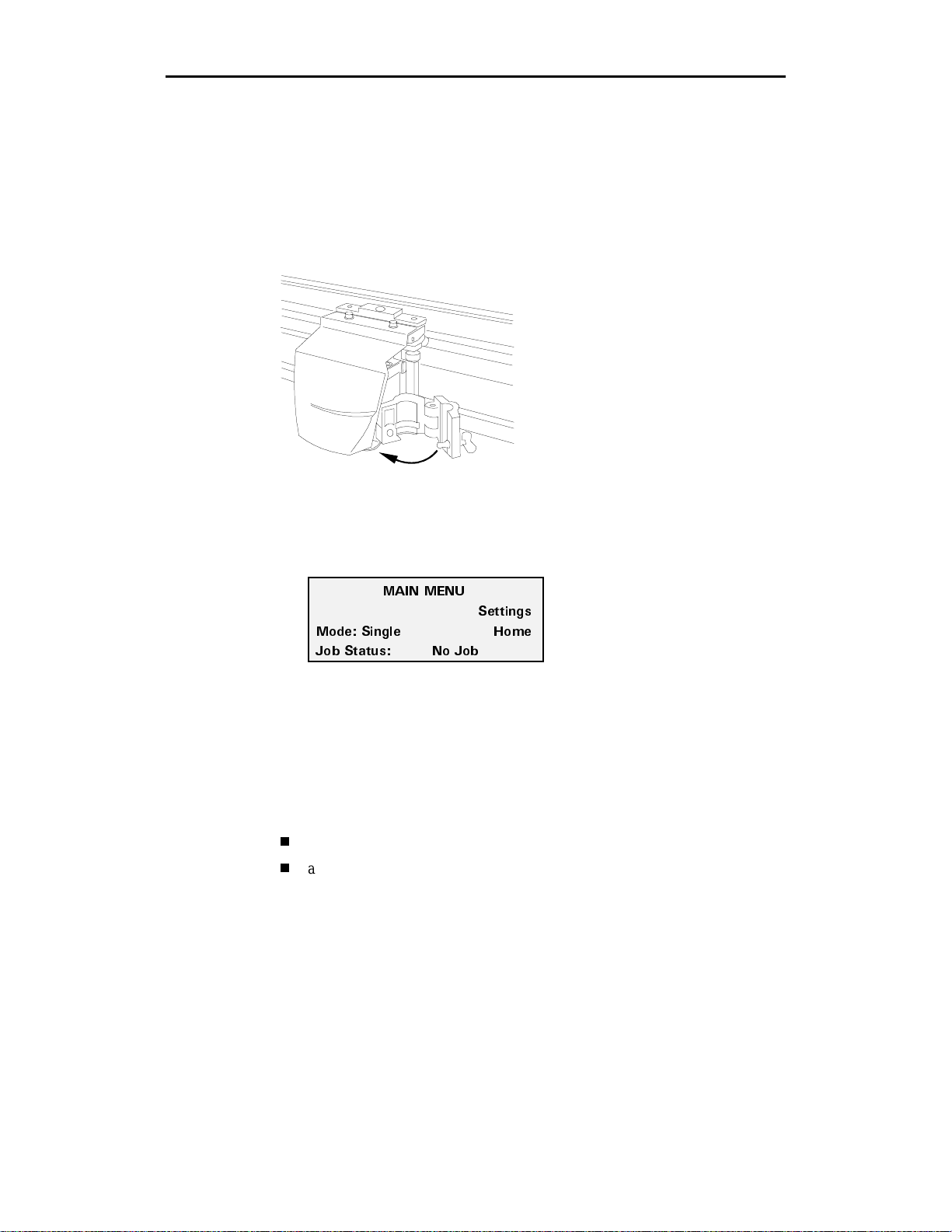
1. Close the bail arms.
2. Close and latch the tool clamp as shown below.
3. Close the plotter cover.
4. Plug in the plotter power cord.
Getting Started 5
5. Turn on the power switch located on the front left side of the plotter. The
Main Menu appears.
/#+0 /'07
/QFG 5KPING *QOG
,QD 5VCVWU 0Q ,QD
Setting up the software
After connecting the plotter to the GA or other sign design system computer,
you need to make the plotter available to the computer through your software
setup program. If you are not using GA as your sign design system, refer to your
software documentation to add the enVision to your system. If you are a GA
user, adding the enVision to your computer is a two-step process:
updating your GA software to add and support the enVision plotter
adding the enVision to the GA list of available plotting and printing devices
5GVVKPIU
Page 10

6 enVision Owner’s Guide
Updating GA software
The enVision plotter is shipped with four 3.5-inch disks. One set of three disks
is service pack 3, which is used to update GA version 6.2 so that you can add the
enVision plotter and allow it to be fully supported and controlled by GA. The
single disk is a driver disk which allows you to add the enVision to your list of
available plotters if your GA is version 6.0 or earlier. The following loading
rules apply:
If you have GA
version then load and the result is
6.21 nothing the GA plot program
supports and controls
the plotter
6.2 the service pack disks
6.0 or earlier the driver disk you can add the
Loading the disks is the same for either the service pack disks or the patch disk:
1. Close all GA programs. It is also a good idea to close any Windows
programs that are running.
2. Put disk 1 of the service pack or the driver disk in the 3.5-inch drive
(usually the a: drive).
3. In Windows 95, click on Start, Run, type
Windows 3.x, click on Run in the Program Manager File menu, type
a:\setup
4. Follow the onscreen prompts while the setup p rogram loads the files.
, then press Enter.
Adding the enVision to GA
After you load the disks, the next step is to add the enVision to the list of
available plotters in the plot program. This addition is performed in the GSP
Setup program.
(GA 6.2 service pack 3)
a:\setup
the GA plot program
supports and controls
the plotter
enVision to the list of
available plotters
, then click on OK. In
1. Open the GSP Setup program.
2. Click on Setup, then click on Plotter/Router. The Add or Delete
Plotter/Router(s) dialog box appears.
Page 11
3. From the Devices box, click on enVision 750 or 375 to highlight it. If more
N
than one plotter is connected to your system, highlight the enVision, then
click Preferences to set the enVision as the default plotter.
4. Click on the port to which the plotter is connected (COM1, COM2, COM3,
or COM4) in the Ports box.
5. Click on Add. The enVision appears in the Ready for Plotting list box.
6. Click on Continue and exit GSP Setup.
Using the control panel and menus
The plotter's control panel contains 10 keys that perform functions such as
positioning the tool head, starting and pausing jobs, and changing settings. The
display on the control panel changes to provide information about the status of
the plotter and offer menu choices.
Note: For an outline of the menu structure, please refer to the reference card at
the back of this manual.
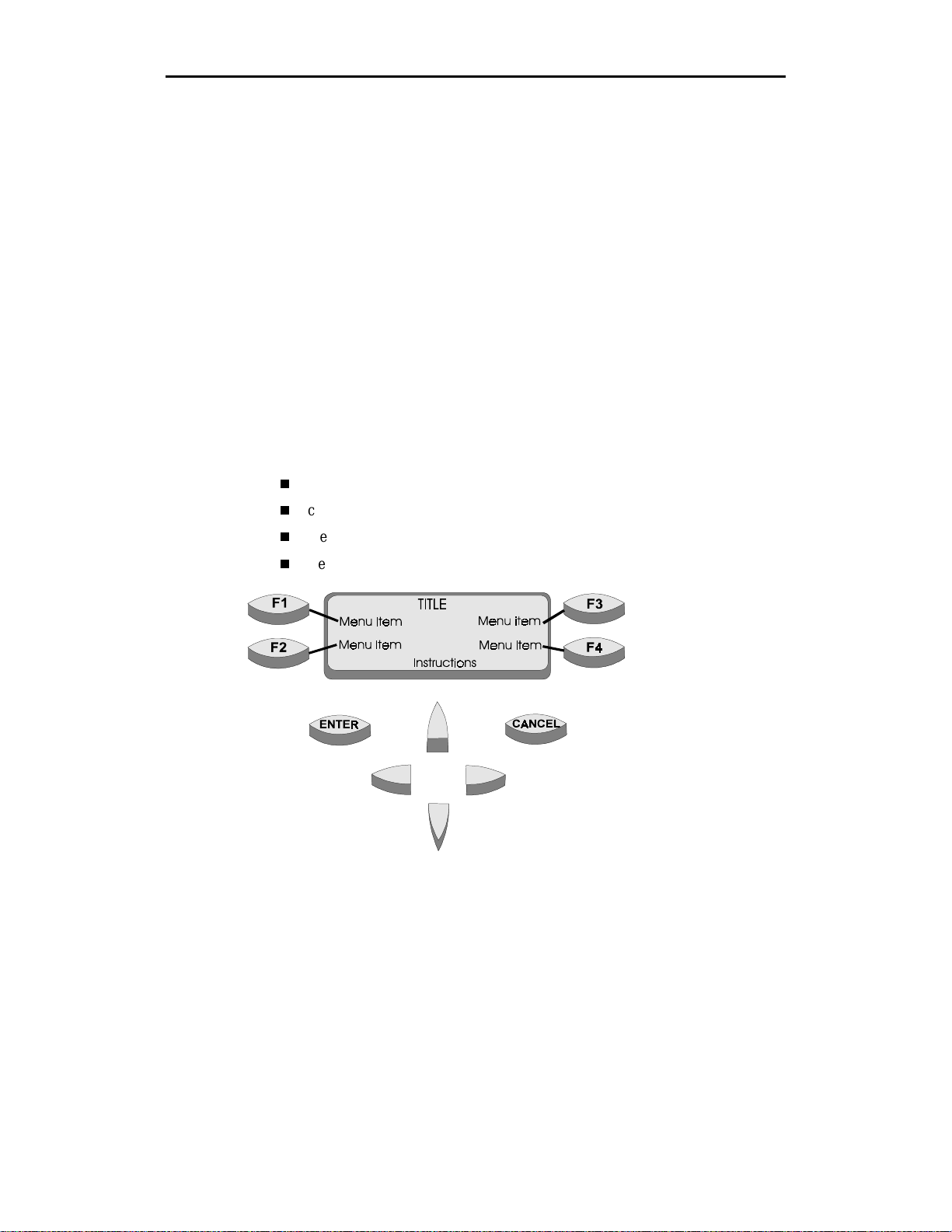
The control panel consists of:
message display
control keys (ENTER and CANCEL)
menu selection keys (F1, F2, F3, F4)
slew keys
Getting Started 7
ote: Function keys are
associated with text in the
message display.
Page 12
8 enVision Owner’s Guide
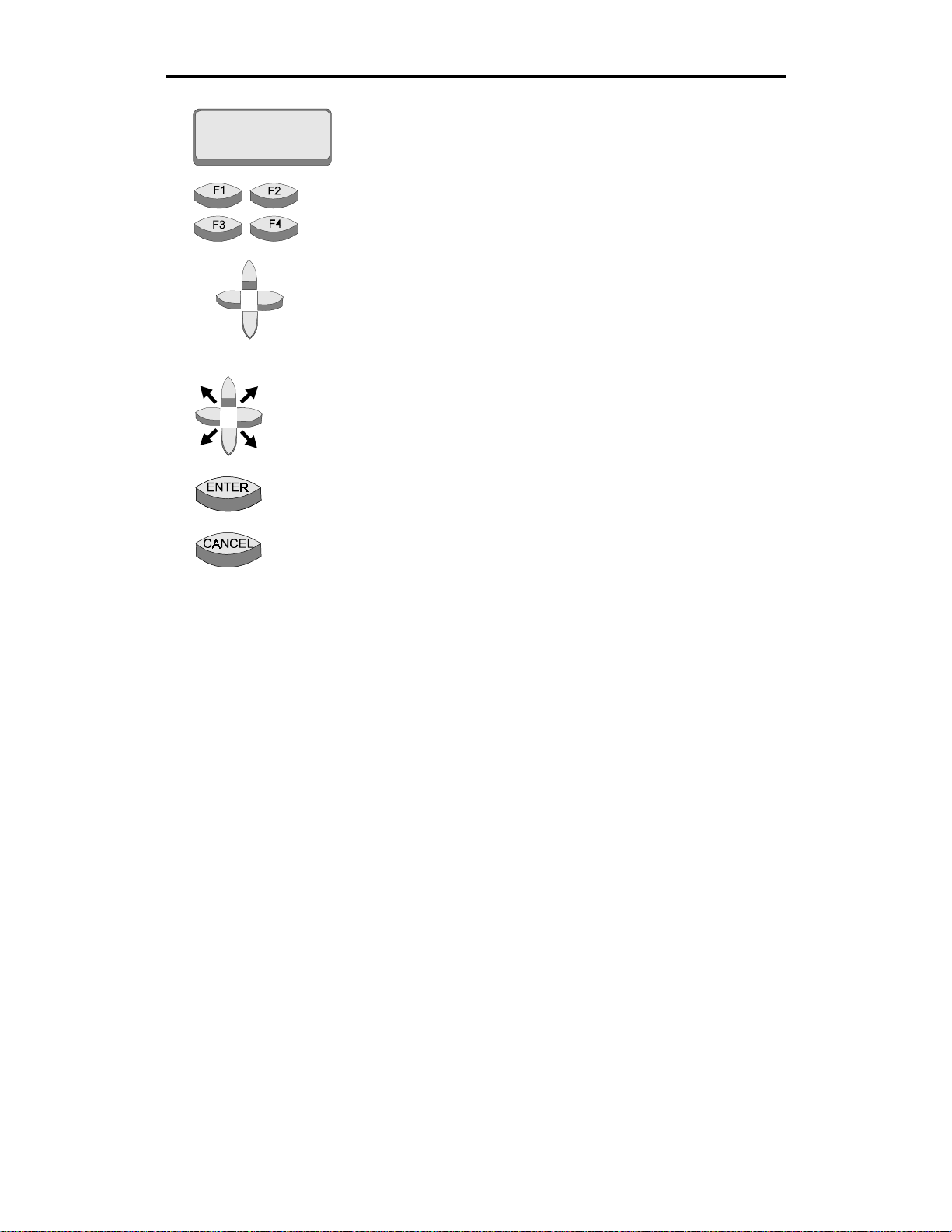
The message display shows menus, instructions, system and job
status, and messages. Each menu has a title (for example, MAIN
MENU). You step through menus by pressing function keys.
The F1, F2, F3, and F4 function keys select other menus and change
parameter values or settings. Their function is based on the text in
the screen associated with each function key.
Slew keys move the tool head and/or the material. The left or right
slew keys move the tool head left or right. The up or down slew keys
move the material forward or backward. Slewing speed starts slowly.
It increases when you continue to hold down the slew key for a few
seconds. Quickly pressing and releasing a slew key will move the
plotter in increments of 0.001".
Slew diagonally by simultaneously pressing the two slew keys
adjacent to the arrow that points in the direction you want to slew.
The ENTER key accepts and records settings when in a settings
menu, or returns to the MAIN MENU when in a submenu.
When a job is running, the CANCEL key stops all motion of the
plotter and terminates any job that is in the plotter, clearing it f r om
the plotter memory. When modifying a setting (such as corners,
speed, or pull down, for example), pressing CANCEL after changing
values will not save the changes nor will it cancel the job. However,
in the next menu that appears, pressing CANCEL does cancel the job
at that time.
Page 13
Loading material
The enVision uses the same punched vinyl film, papers, and masks as all Gerber
plotters. Always insist on Gerber-authorized m aterials for highest quality.
Note: The illustrations for loading material depict the enVision 750 plotter.
Loading material in the enVision 375 is the same except for the first three steps
(putting the material on a vinyl ro ll shaft and installing the shaft on the plotter
stand). For the enVision 375, put the roll of material on the roll holder, then
position the holder approximately 10" (25.4 cm) behind the plotter.
CAUTION: Do not load the material with a tool installed in the tool clamp.
Loading material into the plotter with the tool installed can result in
damage to the blade or the material.
Getting Started 9
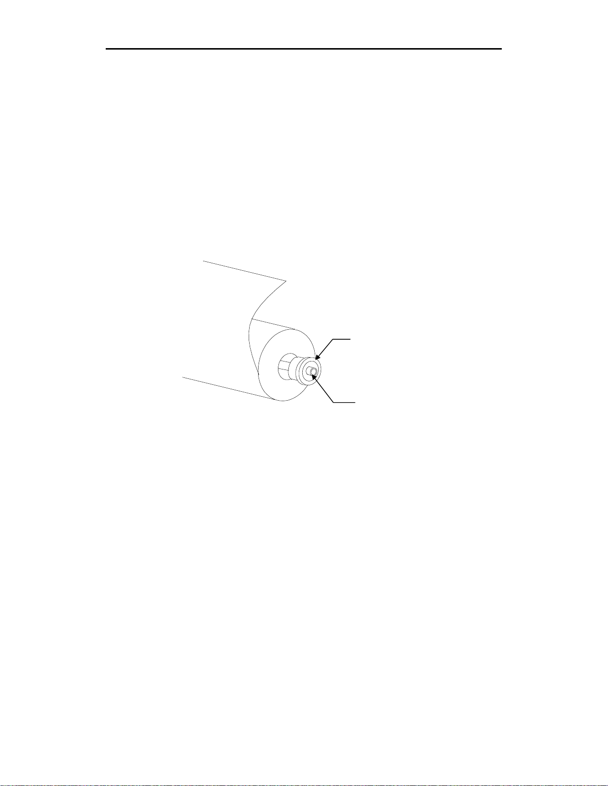
For the enVision 750 only,
1.
of material by inserting the end plug into the cardboard tube.
For the enVision 750 only,
2.
plug.
place a material end plug in each end of the roll
Material end plug
Vinyl roll shaft
insert the vinyl roll shaft tube through each end
Page 14
10 enVision Owner’s Guide
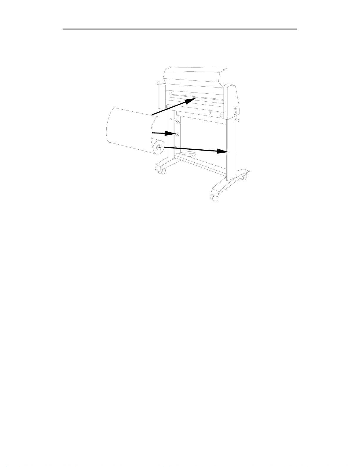
For the enVision 750 only,
3.
inserting the vinyl roll shaft tube in to the slots of the stand as shown below.
4. Press F4, HOME. The three closely-spaced material alignment pins rotate to
the up position and the tool head reorients itself. These three pins match the
three closely-spaced holes in the material for perfect alignment.
position the roll of material on the stand by
Page 15
Getting Started 11
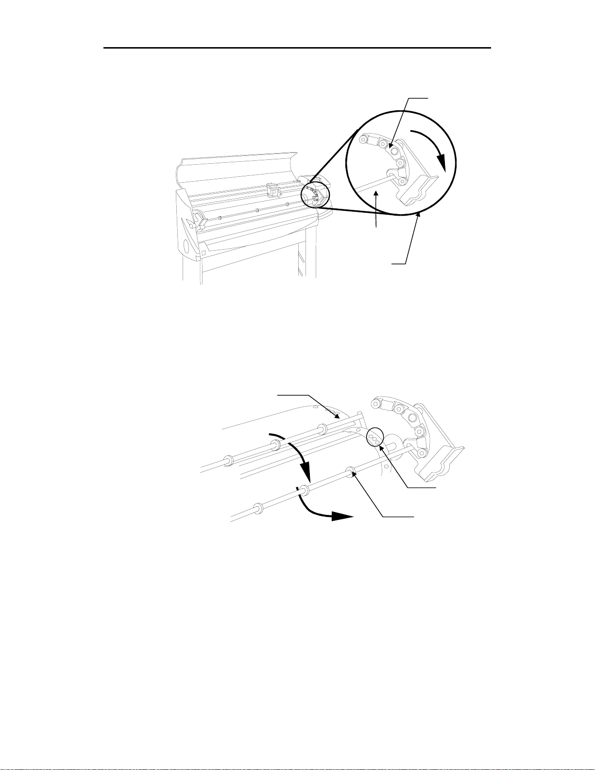
5. Open the bails and the front material guide tube by simultaneo usly pulling
the bail handles forward and down away from the front of the plotter.
Bail
Front material
guide tube
Bail handle
6. Open the rear material guide tube by lifting it up. (See the illustration
below.)
7. Pull the material up toward the plotter, feeding the material from back to
front as shown in the illustration below, ensuring that the material is
underneath the front and rear material guide tubes.
Rear material
guide tube
Material
alignment pins
Front material
guide tube
8. Match the three closely-spaced holes in the material with the three material
alignment pins on the sliding sprocket at the left end of th e plotter. This
sprocket may be shifted slightly left or right to accommodate small
differences in the material width.
Page 16
12 enVision Owner’s Guide
9. On the right end of the plotter, place the three closely-spaced holes on the
alignment pins of the fixed sprocket.
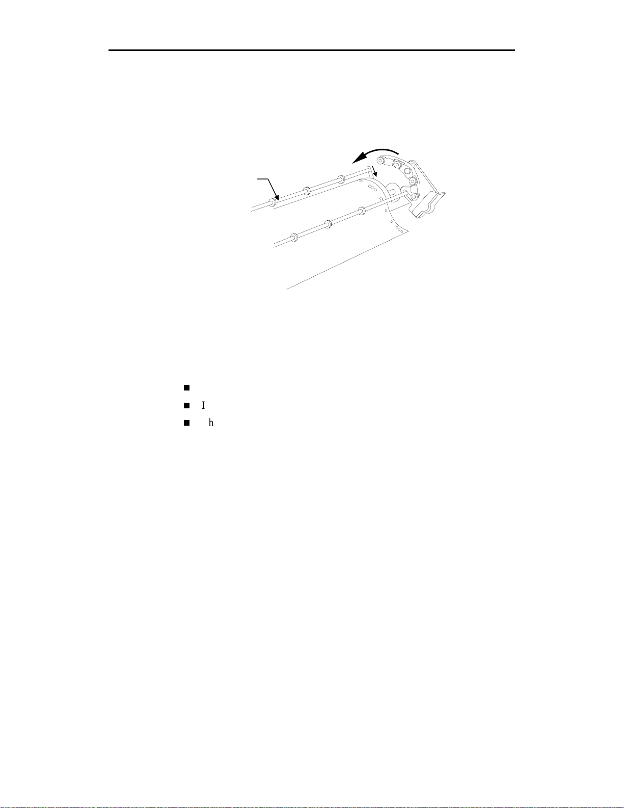
10. Close the rear material guide tube, then adjust (slide) th e left bail so that it
lines up with the sliding sprocket on the left side. Close the bails, which
also closes the front material guide tube, making sure that the left bail is
seated over the pins of the left sprocket.
Rear material
guide tube
Installing tools
The knife, pen, and optional pounce tools are all installed into the tool head the
same way. Before installing the knife for the first time, or af ter changing the
blade, adjust the blade exposure, then load the knife. This paragraph provides
information on:
Adjusting the knife blade exposure
Installing a tool
Changing the knife blade
Note: The GERBER EDGE eyepiece, used to align the knife with the cutter
registration mark printed on the material, is also installed in the tool head the
same way as the tools. For more information on using the plotter with the
EDGE, refer to the paragraph "Using the enVision with the EDGE.”
Adjusting the knife blade exposure
Cut quality is directly related to the correct blade exposure for the material
being cut.
The knife tool holder has hash marks around its circumference. Rotating the
adjustment cap one hash mark, extends or retracts the blade 0.001" (1 mil)
(0.0254 mm). When the blade is pointed towards the ceilin g, rotating the
adjustment cap clockwise increases the blade exposure. Turning the cap counter
clockwise decreases the blade exposure.
Page 17

Getting Started 13
Adjusting the blade exposure to the proper amount is a trial and error process.
You adjust the blade exposure visually, then perform a hand-held test cut on the
material you will be cutting. Evaluate the results, adjust the blade in or out, and
perform another hand-held test cut. Keep repeating this procedure until the depth
of cut permits easy weeding without cutting the material backing.
To set the blade exposure
1. Hold the tool holder with the blade toward the ceiling. Turn the adjustm ent
cap clockwise (to extend) or counter clockwise (to retract) so that the blade
extends beyond the end of the tool holder approximately the thickness of
two sheets of paper. (Note: This is the correct setting for Scotchcal 220
material. Other materials may re quire more or less exposure.)
CAUTION: When performing the next step, do not press too hard on
the material. Too much pressure can damage the blade.
2. Place a piece of the material you will be cutting on a flat surface and,
pressing gently, scribe a circle with the tool by hand.
3. Weed the circle. If it weeds properly without cutting into the backing, the
blade exposure is correctly set for that material.
4. If the material has not been cut all the way through, turn th e adjustment cap
clockwise one or two hash marks to expose more blade. Go back to Step 2.
Repeat the procedure until the scribed circle weeds properly without cu tting
the backing material.
5. If the backing material has been cut, turn the adjustment cap counter
clockwise to decrease the blade exposure. Go back to Step 2. Repeat the
procedure until the backing material is no longer cut and the scribed circle
weeds properly without cutting the backing material.
Page 18
14 enVision Owner’s Guide
Installing a tool
After you adjust or verify the knife blade exposure:
1. Move the tool head to the middle of the plotter by pressing a slew key.
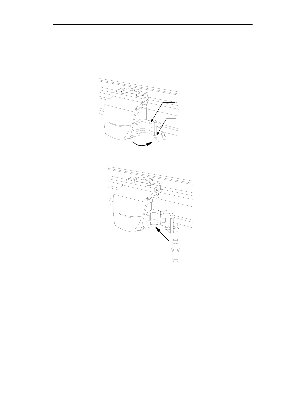
2. Open the tool clamp by turning the latch fastener counterclockwise and
gently pulling the clamp open.
3. Place the swivel knife tool into the tool head, making sure that the swivel
knife tool collar fits into the groove in the tool head.
Tool clamp
Latch fastener
Page 19
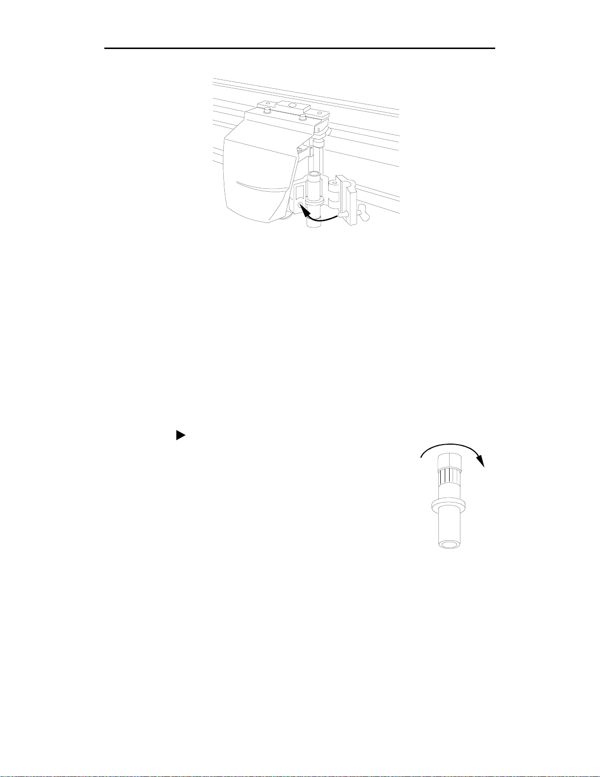
4. Close the clamp and secure it by turning the latch fastener clockwise.
Changing the knife blades
Blades are available in 30°, 45°, and 60° angles. The 30° and 60° blades are
designed for cutting thin and thick materials r espectively; the 45° blade is
designed for most materials.
The knife blade will dull slightly after cutting thousands of characters. Blade
wear is normal and always a gradual change. Adjusting tool settings, as
described in the next section, can extend blade life.
Getting Started 15
Because they are ground to a controlled length, the blades cannot be
resharpened. A sudden decline in cutting quality indicates that the knife blade is
chipped. Replace and discard any chipped blade.
WARNING: Handle blades carefully. Carbide blades are brittle so they can
easily chip and they are extremely sharp.
To change the blade
1. Hold the tool so the blade points toward the
ceiling.
2. Remove the adjustment cap by turning it
counterclockwise until is comes completely
off.
3. Remove the old blade by pulling it straight out
with a pair of tweezers.
Page 20

16 enVision Owner’s Guide
4. Put in the new blade using tweezers. Press the
tip lightly with the flat of your fingernail to
ensure that it is all the way in.
5. Put the cap back on carefully and turn it
clockwise.
Adjust the blade further as needed by following
the directions in the previous paragraph,
“Adjusting the knife blade exposure.”
Page 21

enVision Overview
Both Gerber enVision plotters have many features that make them easy and
convenient to use:
The enVision 750 draws, cuts, and pounces designs up to 27.25 inches
(692.15mm) high. Using the GRAPHIX ADVANTAGE system Panel
feature, the enVision can cut text or graphics in strips up to 96 feet long (29
meters) and 27.25 inches (692.15mm) high. The enVision 375 draws, cuts,
and pounces designs up to 13.25 inches (336.55 mm) high and can also cut
EDGE print jobs.
Jobs can be controlled entirely from GRAPHIX ADVANTAGE Version
6.2. Selecting a specific material causes appropriate tool settings for that
material to be sent automatically to the enVision.
Pounce instructions can also be sent from GRAPHIX ADVANTAGE 6.2.
Tool settings and other parameters can also be set right at the plotter.
The enVision calculates the job extremities when it receives a job. If the job
will not fit on the Y axis or the starting position must be adjusted, it
displays an appropriate message.
17
Easy material loading with X axis homing which bring s th e three m ater ial
alignment pins on the sprockets up to top center for the quickest, easiest
loading possible.
Repeats (up to 9999 copies) of the last job plotted (up to 200 kb) can be run
from the enVision.
You can suspend a job, move the material for easy viewing, and resume the
job without affecting the material or job.
Allows for plotter firmware upgrade by downloading new firmware into the
plotter from the PC.
Page 22

18 enVision Owner’s Guide
The plotting process
The enVision plotter uses a knife installed in the tool he ad to cut shapes in the
material (usually vinyl). After the job is cut, you remove the excess material
(called weeding the job) from the design. Cutting accuracy and weeding ease
depend on matching the tool settings to the material being cut. Tool settings are:
force
corners
speed
acceleration
Tool setting tips are described in the following paragraphs.
Tool settings
The four tool settings − force, corners, speed, and acceleration − must be
matched to the material being cut. In the back of this manual is a card with
recommended tool settings for various materials. These tool settings are startingpoint guidelines. Quality cutting is dependent on the job being cut. For example,
if a job has many long, straight lines, you can cut at increased speed and
acceleration. If a job has many corners and curves, you may want to use less
speed and acceleration. In general, the best possible cut quality is achiev e d by
using the minimum tool force that provides easy weeding.
Also note that occasional adjustments need to b e made to too l settings based on
blade wear. Changing settings up or down do not mean that there is a problem
with the plotter. For example, blade wear may require changing the settings to
maintain optimum cutting quality. Other factors, such as temperature or
humidity changes or cutting small text, may also require changing the tool
settings.
Material selection
The plotter firmware contains a table of materials (called rule sets) with
corresponding tool settings for cutting Gerber materials. When you select the
material you plan to cut in the plotter Settings Menu, you automatically set the
factory default tool settings for that material. A rule sets guide chart is provided
on reference cards in the back of this manual.
Note: There are additional rule sets built into and available in the GA plot
program as described in the following paragraph.
For more information on setting and chang ing th e rule set v a lues, refer to the
section "Choosing Tool Settings" on page 28.
Page 23

Using the enVision with GA
The enVision can be completely controlled from the GA version 6.2 (and
higher) plot program by using controls in the Plotter Settings dialog box.
Use of this dialog box is explained in the GRAPHIX ADVANTAGE Reference
Volume 1 manual. Several comments specific to using the dialog box with the
enVision are explained here.
enVision Overview 19
When an enVision plotter is selected, the color and material (also called the
vinyl family) is displayed.
The GA 6.2 plot program has a rule set − as described in the previous
paragraph − as part of the program. This rule set is more comprehensive
than the rule set built into the plotter. The Plotter Setting s slid e bars display
the default settings for the material, and the settings can be changed using
the slide bars.
Note: The plot program in GA version 6.0 and earlier does not contain a
rule set. When using these versions, settings may be adjusted at the
enVision control pad.
When the Use Settings check box is turned on, the rule set for the displayed
material is transmitted to the plotter and overrid e s any r ule set turned on in
the plotter. If the Use Setting check box is turned off, the rule set in the
enVision is used to plot the job.
Page 24

20 enVision Owner’s Guide
Note: There is also a rule set menu selection item in the enVision
(Operational Setup menu, System, Rules, Select Rule Usage menu). If this
menu item is set to When Received, the GA overrides the rule set in the
plotter. If this menu item is set to Never, the enVision plotter ignores the
rule set sent from the GA and uses its own rule set for the material.
The Plotter Prompts check box is used when cutting EDGE jobs. for a
description of this feature, refer to the next paragraph.
Using the enVision with the EDGE
The enVision 375 is capable of cutting EDGE printed jobs as described in the
GERBER EDGE Owner's Guide. The following additional capabilities are
provided when cutting with the enVision plotter:
When the Plotter Prompts check box is turned off in the Plotter Settings
dialog box, the job starts when you press Start Job (F1 on the enVision
control panel). If the check box is turned on, the control panel displays the
job name, vinyl color, and vinyl family. At this time, you use the EDGE
eyepiece to register the knife with the registration target. After you
complete registration, when you press F4 the job starts.
When you send a job to the EDGE for printing from the plot program in GA
version 6.2 or higher, turn on the Center Target check box. This prints the
target in the center of the Y axis and makes it easier to install the eyep iece
in the tool head.
Page 25

Plotting Jobs
You can send a job to the plotter to be output with a pen, a pounce tool, or a
knife. Jobs sent to the plotter are held in the plotter’s memory. The Job Status
changes from
the plotter waits for you to start the job except when in Multi mode ( see
“Plotting multiple jobs” on page 23).
5VCTV,QD 5GVVKPIU
/QFG 5KPING *QOG
,QD 5VCVWU 4GCF[
Job status
0Q ,QD
/#+0 /'07
to
4GCF[
, and
5VCTV,QD
21
blinks. When a job is in memory,
Job Status in the bottom line of the disp lay shows the condition of the plotter.
The function key choices depend on the Job status as shown in the table below.
Job Status Condition Possible Action
0Q ,QD
4GCF[
4WPPKPI
2CWUGF
No job data in plotter
memory.
Plotter is waiting for user to
start the job.
Plotter is running a cut job or
a pen job.
Job is temporarily stopped. Start-Job, Cancel, Menu
Menu
Start-Job, Cancel, Menu
Pause Job, Cancel, Menu
Page 26

22 enVision Owner’s Guide
Plotting a single job
Use Single mode to plot a single job. Single mode allows you to:
change material between jobs
pen plot using paper before cutting vinyl
reposition the start of the next job
Each job plots and then waits for you to press Start-Job again to begin the next
job.
1. Press F2 to toggle between Single mode and Multi mode. Choose SINGLE.
(
Mode: Single Home
Job Status: No J ob
2. Send the job to the plotter. When the job reaches the plotter, the status
changes from
dotted box around Start-Job in the diagram below).
3. Press F4, HOME to rotate the three closely-spaced material alignment pins
to the top for easy material loading.
MAIN MENU
0Q ,QD
to
Settings
4GCF[
, and
5VCTV,QD
blinks (indicated by the
4. Load the material and install a tool in the plotter.
Note: Using the left and right slew keys to move the tool head near the
center may make it easier to load the ma terial.
5. Use the slew keys to position the tool where you want plotting to begin.
6. Press F1, Start-Job.
MAIN MENU
(
Start-Job Settings
Mode: Single Home
Job Status: Ready
Page 27

Plotting Jobs 23
I
7. The plotter displays the vinyl type and color required by the job. This
information enables you to verify that you have the correct material loaded
for the job. This screen only appears if you are using GA version 6.2 and
the Plotter Prompts checkbox turned on.
Job: →PLT1474.TMP
Color: White
Type: 220
Press F4
8. Press F4.
The job starts and Job Status alternately displays
(GA version 6.2 only). While the job is running, you can press F1 to pause it and
F1 to re-start it again.
(
2CWUG,QD 5GVVKPIU
/QFG 5KPING
,QD 5VCVWU 4WPPKP
Note: The cover must be closed for the job to run.
After completing the job, the Job Status returns to
several jobs, the Job Status displays
Start-Job to plot each job.
Plotting multiple jobs
Multi mode lets you plot several jobs without having to press Start-Job between
each one. When one job finishes plotting, the next job begins immediately.
When all jobs in memory are plotted, the enVision waits for another job and will
plot it as soon as it is received. Multi mode is best used for jobs that require the
same material.
1. Press F2 to switch between Single mode and Multi mode. Choose
/#+0 /'07
4WPPKPI
0Q ,QD
4GCF[
and you will need to press F1,
and the percent done
. If you have sent
/WNVK
.
/#+0 /'07
5VCTV,QD 5GVVKPIU
(
/QFG /WNVK *QOG
,QD 5VCVWU 4GCF[
2. Send the jobs from your computer to the plotter. When the jobs are received
in the plotter’s memory the Job Status changes from
5VCTV,QD
blinks (indicated by the dotted box around Start-Job).
0Q ,QD
to
4GCF[
and
Page 28

24 enVision Owner’s Guide
I
Note: If you press F1 before sending the job, it starts immediately when
received by the plotter. In this case, you must load the material and install
the tool before you send the jobs to the plotter. (See “Running multiple jobs
automatically” on page 25.) This feature is convenient if the plotter is in a
remote location separate from the computer.
3. Press F4, HOME to rotate the three closely-spaced alignment pins to the top
for easy material loading.
4. Load the material and install the tool in the plotter.
Note: Using the left and right slew keys to move the tool head near the
center may make it easier to load the ma terial.
5. Use the slew keys to position the tool where you would like plotting to
begin.
6. Press F1, Start-Job to begin plo tting the first job. Subsequent jobs will not
require pressing Start-Job again.
(
5VCTV,QD 5GVVKPIU
/QFG /WNVK *QOG
,QD 5VCVWU 4GCF[
/#+0 /'07
Note: In Multi mode, the job/color/type displa y is bypassed even if the
Plotter Prompts check box is turned on.
While the job is running, you can press F1 to pause the job, and F1 again to
restart it just like in Single mode. Job Statu s alternately displays
4WPPKPI
and
the percent done (GA version 6.2 only). When the jobs are plotted, the Job
Status remains at
4WPPKPI
and Mode remains set to
/WNVK
. If you send another
job to the plotter, it will begin plotting im m ediately .
/#+0 /'07
Pause-Job
/QFG /WNVK *QOG
,QD 5VCVWU 4WPPKP
5GVVKPIU
Page 29

Running multiple jobs automatically
I
In Multi mode, if you press F1, Start-Job before sending a job to the plotter, the
job will begin as soon as the plotter receives it without requiring another key
press, provided the following conditions are met:
Material has been loaded and a tool is installed.
The cover is closed.
A slew key has not been pressed to reposition the tool head or material.
(This is to prevent the plotter from starting while the knife is being
positioned.)
You can also slew between jobs, but must then press the Start-Job key to start
the next job when it is received.
Pausing and restarting a job
Pausing a job suspends it temporarily. You can pause a job by lifting the cover
or pressing F1, Pause-Job. The plotter stops cutting or plotting at the end of the
current shape. After pause, you can look at your job by using the slew keys to
move the material. When you restart the job, the plotter resumes repositions
itself and starts cutting at the position where it stopped.
Plotting Jobs 25
Note: Once a job has begun, slewing will not affect the job.
1. To pause a job, press F1, Pause-Job.
/#+0 /'07
(
2CWUG,QD 5GVVKPIU
/QFG 5KPING
,QD 5VCVWU 4WPPKP
2. The current Job Status changes to
2CWUGF
. To restart the job, press F1,
Start-Job. The plotter returns to the previous position and resumes cutting or
plotting.
/#+0 /'07
(
5VCTV,QD 5GVVKPIU
/QFG 5KPING
,QD 5VCVWU 2CWUGF
When all jobs have plotted the plotter returns to
0Q ,QD
status.
Page 30

26 enVision Owner’s Guide
Opening the cover has the same effect as pressing the Pause-Job command.
With the cover open, you can use the slew keys to move the material so that you
can view the job. Once the cover is closed, you can re-start the job by pressing
F1 and the tool returns to where it paused.
Canceling a job
To cancel a job press CANCEL. The
then the plotter stops and returns to the MAIN MENU. Multiple jobs in the
spooler are cleared one at a time by pressing CANCEL.
Tip: When you clear a job, remember to reposition the tool for plotting the next
job.
,1$ %.'#4'&
Automatically fitting a job on the plotter
When the enVision plotter is used with GA version 6.2, a feature is available
called Autofit which automatically positions the to ol head so that it cuts the
entire job. This feature only works on cut-only jobs, not EDGE print and cut
jobs. For example, if you send a 9" box to the enVision 375 plotter and the
carriage is in the middle of the Y axis, the following message appears in the
display.
,QD YKNN PQV HKV
5NGY TKIJV VQ CFLWUV
+IPQTG #WVQHKV
5NGY ( ( %CPEGN
If you choose Ignore and start the job, the plotter display s a m essage that the job
will be clipped. Only what fits on the plotter will be cut. If you choose Autofit,
the tool head moves to where the job will fit and displays a message telling you
that the job now fits. Pressing ENTER starts the job.
message displays briefly,
This feature is for vinyl cut-only jobs. If you get this message with an EDGE
job, first check the target alignment, then choose Ignore. If you choose Autofit
for an EDGE job, the cut will not be correct.
Job clipped message
If the enVision plotter is used with GA version 6.0 or earlier, if a job is too large
for the plotter it displays a "Job clipped" message. This means that the job
extends beyond the Y axis boundaries. To remove the message, press any key to
continue and start the job. If you are in Multi mode and one of the job s is too
large, the plotter starts automatically cutting until it comes to the job that is too
large. It will display the message and cut the job, then stop and not cut any
remaining jobs until you press any key.
Page 31

Missing tool message
If no tool is loaded in the plotter, when it is first turned on the plotter d isp lays a
message telling you that there is no tool loaded. If you start the job anyway, the
message disappears and the job starts. The message is not repeated even if you
send another job.
Plotting Jobs 27
Page 32

28 enVision Owner’s Guide
Choosing T ool Settings
As previously stated, cutting accuracy and weeding ease depend on matching the
tool settings to the material being cut. Tool settings are:
force
corners
speed
acceleration
Normally, tool settings are automatically set using the rule sets in the GA as
previously described (Use Settings check box in the Plotter Settings dialog box).
The tool settings − based on the material being cut − can also be set on the
enVision as follows:
1. In the MAIN MENU, press F3, SETTINGS to open the Settings menu. If
the material shown is what you are using, press ENTER to return to the
MAIN MENU. If it is not the correct material, press F3, MATERIAL to go
to the Select Material Type screen.
Note: Pressing F1, (default) on the Settings menu, resets all of the tool
settings for the selected material to the factory presets.
SETTINGS MENU
(default) Material
Corners Force
** Scotchcal220 **
(
2. Use F3 or F4 to toggle up or down through the list of ma ter ials. Select the
one you are using by pressing ENTER. (See “Fine tuning the enVision” on
the next page for more information on using this screen to fine tune your
plotter to the job.)
SELECT MATERIAL TYPE
+
* Scotch cal220 * -
Press ENTER key to Accept
(
(
3. The selected material will display on the Settings menu. Press ENTER
again to return to the MAIN MENU.
The correct tool settings for that material are now set.
Page 33

If necessary, you can modify the force and corners settings right in the Settings
menu. These modifications to the factory defaults will remain in effect for that
material until you:
manually reset the modifications to zero
press default in the Settings menu to r eturn the settings for that material
back to the factory settings
Note: Tool settings sent from GRAPHIX ADVANTAGE will override enVision
tool settings during a job unless this feature is tu rned off either in GA or in the
enVision.
Fine tuning the enVision
To ensure optimal cutting, it is important that the enVision is properly set up for
the specific material to be cut. This is accomplished by:
Ensuring that the knife blade exposure is correct for the material to be cut.
See “Adjusting the blade exposure” on page 12.
Choosing the correct material in GA or the Settings menu.
In most cases, proper blade exposure and the correct material choice will
provide optimal cutting. However, as the blade becomes slightly worn, you may
wish to fine tune the Force and Corners settings to provide the best quality
cutting.
Note: Use the following procedures for adjusting force and corners only if you
are not using GRAPHIX ADVANTAGE rules. The rules will override these
adjustments.
Choosing Tool Settings 29
Once you have the knife blade exposure correctly set (see “Adjusting the blade
exposure” on page 12), you can fine tune the enVision by first adjusting the
force, then the corners. You can make the adjustment from GA by means of
graphic sliders in the Plotter Setting dialog box. On the enVision, the setting is
adjusted by means of a bar graph in the display that either reduces or increases
the default setting for that material. In the example below, the F3 (or F4) k ey ha s
been pressed five times to increase the tool force for the selected material by
five clicks.
#&,756 611. (14%'
(
(
NGUU OQTG
'06'4 MG[ VQ #EEGRV
❚ ❚ ❚ ❚❚
(
(
Page 34

30 enVision Owner’s Guide
Pressing the F1 (or F2) key would cause the bar graph to move in the opposite
direction, retracting toward the zero point one click for each press. When it
reaches the zero point, the factory default has been reset. Continued pressing of
the F1 or F2 key will extend the bar graph to the left of the zero point and reduce
the factory default by the number of clicks that F1 is pressed.
Keep in mind:
These settings are retained even after the power has been shut off.
They apply only to the currently selected material.
These adjustments will be overridden by GRAPHIX ADVANTAGE rules
unless this feature is turned off.
Adjusting the force
You obtain optimum cutting from the plotter by using the least amount of tool
force that will cut the material so that it weeds easily. If you conclu de that an
adjustment of the tool force will improve cutting, you can make the change in
GA, or use the following procedure to adjust the force on the enVision if you are
not using GRAPHIX ADVANTAGE rules.
The tool force is the downward pressure that the tool holder applies to the
material with the tool. This pressure ensure s uniform cuts and pen lines.
Increased tool force presses harder on the material. The range is .5 to 16 ounces
(14 to 448 gm) in increments of 0.5 oz. (14 gm).
Several factors affect tool force and require setting changes. Below are some
initial suggestions:
Blades must be properly installed and adjusted to the correct depth in
the tool holder assembly. (See “Adju sting the blade exposure” on
page 12.)
If the pressure is set too high, the knife will not p ivot at co rner s and
will begin to cut through the material.
If your pen does not make a clear dark line, you may wish to increase
the tool force setting.
Worn blades require a higher tool force setting. You may wish to
increase the tool force as required for easy weeding. However, before
increasing tool force, check to see if the blade is in good condition.
Increasing the force may also necessitate changes for the corners and
speed settings to maintain a good cut quality.
Heavier material, such as reflective vinyl, requires increased tool force
settings.
Drawing, pouncing, cutting, and blade angle all affect the tool force
setting.
Page 35

Choosing Tool Settings 31
To adjust the force
1. Press F3, SETTINGS.
/#+0 /'07
5GVVKPIU
/QFG 5KPING *QOG
,QD 5VCVWU 0Q ,QD
(
2. On the Settings menu, press F4, FORCE. (Scotchcal 220 is shown as an
example only.)
5'66+0)5 /'07
FGHCWNV /CVGTKCN
%QTPGTU (QTEG
5EQVEJECN
Note: Pressing F1, (default) on the Settin gs menu will resets all of the tool
(
settings only for the selected material to the factory presets.
Note: This change in tool force applies only to the material shown in the
menu above.
3. Press the F1 or F2 keys to decrease the force, or press the F3 or F4 keys to
increase the force. For each keypress, the bar graph extends to the left or
right one increment to indicate the amount of change.
#&,756 611. (14%'
(
( (
NGUU OQTG
'06'4 MG[ VQ #EEGRV
❚ ❚ ❚ ❚❚
(
4. Press the ENTER key to accept the new setting and return to the Settings
menu.
Note: Keep in mind that adjustments made to force in the Settings menu (see
“Adjusting the force” on page 30) are added to the new force setting you have
just made. If you don’t want that to happen, you must go back to Force in the
Settings menu and return the bar graph to its zero point. Also, these changes can
be made while a job is running. In this menu, pressing CANCEL does not save
the changes and does not cancel the job.
Page 36

32 enVision Owner’s Guide
Corners
In swivel blade technology, the knife tip is always slightly behind the center of
the tool holder and the knife offset is the distance between the knife center and
the knife tip. Adjusting the amount of corner rounding in the firmware tells the
plotter to compensate for this distance. It ensur es that the knife is cutting the
center line of the shape and that the corners will be precise angles. An inaccurate
corner rounding adjustment will cause poor cutting qu ality and difficult
weeding.
The enVision plotter firmware provides a corner rounding adjustment feature
(corners) to help you ensure accurate corner cutting. To determine what corners
adjustment to make, cut a 1/2" (12 mm) test square. Examine the corners
(possibly with a magnifying glass) and compare them to the diagrams below. If
you determine that a corners adjustment is necessary, you can make the
adjustment in GA or follow the procedure on the next page if you are not using
GRAPHIX ADVANTAGE rules. After you have made the adjustment, cut
another test square and check it again. Continue to adjust and test until you have
precise corners.
Knife blade
Offset
The corners adjustment in the example at the
left is too large. In this case, what should be
a square corner is not well formed because
the plotter cuts too far beyond the corner.
Page 37

To adjust the corners
1. On the Settings menu, press F2, Corners.
5'66+0)5 /'07
FGHCWNV /CVGTKCN
(
%QTPGTU (QTEG
5EQVEJ%CN
Note: Pressing F1, (default) on the Settings menu resets all of the tool
settings for the selected material to the factory presets.
Choosing Tool Settings 33
The corners adjustment in the example at the
left is too small. In this case, what should be
a square corner is not well formed because
the plotter did not cut far enough before
turning the corner.
Note: This corners adjustment applies only to the currently selected
material.
2. Press the F1 or F2 keys to decrease the corner sharpness, or press the F3 or
F4 keys to increase the corner sharpness. For each keypress, the bar graph
extends to the left or right one increment to indicate the amount of change.
5*#42 %140'45
NGUU OQTG
( (
'06'4 MG[ VQ #EEGRV
❚ ❚ ❚ ❚❚
((
3. Press the ENTER key to accept the new setting and return to the Settings
menu.
Note: Keep in mind that adjustments made to corners in the Settings menu are
added to the new corners (knife offset) setting you have just made. If you don’t
want that to happen, you must go back to Corners in the Settings menu and
return the bar graph to its zero point.
Page 38

34 enVision Owner’s Guide
Advanced enVision Functions
Previous sections presented information on basic enVision operations such as
loading material, installing tools, plotting a job, and choosing tool settings. This
section provides information about additional enVision functions including:
repeats
material pull-down
pouncing
customizing tool settings
factory default settings
communications
tests
To open the advanced Operational Setup menu so that you can use the advanced
functions, hold down the ENTER key and press F3.
Repeats
CAUTION: You should not attempt these procedures unless yo u a re very
sure you understand exactly what you are changing and the effects it will
have on the operation of your plotter.
Repeats allows you to reproduce the job you have just plotted up to 9999 times.
You must run a job first in order to repeat it. There are small differences when
you run Repeats in Single mode and Multi mode.
Single mode The plotter stops before it plots each of the repeats. This
allows you to change materials or reposition the start of
the job before plotting the next repeat.
Multi mode The plotter runs all the repeats without stopping
between each repeat.
Note: Jobs larger than 200KB cannot be repeated locally. A message appears if
this is attempted.
Page 39

Advanced enVision Functions 35
Send a job to the plotter and plot the job. When the job finishes, the job status
displays
0Q ,QD
if you are running in Single mode and
4WPPKPI
if you are
running in Multi mode.
To repeat a job
1. Press F3 while holding down the ENTER key for the Op er ationa l Setup
menu.
2. Press F4, Misc.
12'4#6+10#. 5'672
5GVVKPIU 5[UVGO
6GUV /KUE
'06'4 HQT /CKP /GPW
(
3. Press F1, REPEATS.
/+5% 5'66+0)5
(
4GRGCVU 2QWPEG
2WNNFQYP &GHCWNV
'06'4 HQT /CKP /GPW
4. Press F3 to increase or F4 to decrease number of copies.
'06'4 07/ 1( %12+'5
4GRGCVU
EQRKGU
'06'4 -G[VQ #EEGRV
5. Press ENTER to record the entry and return to the MAIN MENU which
now has a counter to show the number of repeats remaining. The counter
will decrease as each repeat is completed.
To terminate a repeating job, press CANCEL. The job stops and all repeats are
cleared. A new number of repeats may be set without resending the job.
Note: Do not send new jobs to the plotter while running repeats. New jobs will
be queued at the end of the repeated job sequence.
Page 40

36 enVision Owner’s Guide
Material pulldown
Prior to plotting, the plotter unrolls (pulls down) a specific length of material
from the supply roll. This is an automatic feature that prevents pulling the
material directly from the roll at high speeds during the job which could lead to
poor cut quality. The enVision will pull down as much material as it needs for a
job up to the amount set. (The factory default is 12".) If you are using GA rules,
the length to pull down will be sent by GA, otherwise, the enVision calculates
the length. The pulldown range is 4" to 48". Shortening the pulldown may result
in multiple pull-downs for longer jobs.
1. Press F3 while holding down the ENTER key for the Op er ationa l Setup
menu.
2. Press F4, Misc.
12'4#6+10#. 5'672
5GVVKPIU 5[UVGO
6GUV /KUE
'06'4 HQT /CKP /GPW
3. Press F2, PULLDOWN.
4GRGCVU 2QWPEG
(
2WNNFQYP &GHCWNV
'06'4 HQT /CKP /GPW
(
/+5% 5'66+0)5
4. Press F3 to increase the number of inches or F4 to decrease the number of
inches.
'06'4 27..&190 &+56
2WNNFQYP
KPEJGU
'06'4 -G[VQ #EEGRV
(
(
5. Press ENTER to set the value and return to the Misc Settings. Pressing
CANCEL restores the previous value.
6. Press ENTER to return to the MAIN MENU.
Page 41

Pouncing
Pouncing is a technique used to create a perforated graphic outline on paper.
Pouncing creates a perforation in the material instead of cutting or drawing on it.
It requires a special Gerber tool that can be purchased separately. The pounce
tool looks like an awl (or a sewing needle) and is driven down into the paper,
then moved to make a small rip in the paper. A pounce pattern can be used to
align vinyl letters on a large job or chalk an outline for letters or artwork that
will be hand-painted.
Pounce patterns
The pounce pattern is like a dotted line, with the dots representing the tear s, and
the spaces between the dots representing the untorn areas. The pattern length is
the distance from the beginning of one tear to the beginning of the next. (See the
diagram below.) The percent down is the proportion of the pattern length
represented by the length of the dot.
Advanced enVision Functions 37
50% down
Untorn portion
Percent down
length that will be cut into the material.
Note: When pouncing small objects or text, use the short (50% down) setting.
Even on a long job, if there is no pounce point at the corner, distortion of the
shape can occur.
Using the enVision to pounce is as simple as replacing the swivel knife with a
pouncing tool and selecting a pounce pattern in GRAPHIX ADVANTAGE 6.2
or other design software. If necessary, you can also control pouncing from the
enVision itself as described on the following page.
is the percentage of the pattern
Pattern length
includes the rip and the space
To pounce from GRAPHIX ADVANTAGE 6.2
1. In GA output the job to GAPlot32, activate the Pounce checkbox in the
Plotter Setting dialog box. (Refer to GRAPHIX ADVANTAGE 6.2 Reference
Volume 1 for specific instructions. If you are using other design software
that sends pouncing instructions, refer to your software manual.)
.
Page 42

38 enVision Owner’s Guide
2. Choose the pounce pattern you want to use: short, medium, long, or custom.
(If you choose custom, you must choose the pattern length and the percent
down.)
Setting Pattern Length Percent down
Short 0.050" (1.27 mm) 50
Medium 0.200" (5.08 mm) 25
Long 0.500" (12.7 mm) 10
3. Choose the material you want to pounce.
4. Send the job to the plotter.
5. Load the material you are going to pounce into the plotter.
6. Install the pounce tool.
7. Press F1, Start-Job to run the job.
To pounce from the enVision
Turn on pouncing by selecting a pattern according to the procedure below.
(Pouncing can also be set from GRAPHIX ADVANTAGE 6.2.)
1. Press F3 while holding down the ENTER key for the Op er ationa l Setup
menu.
2. Press F4, Misc.
12'4#6+10#. 5'672
5GVVKPIU 5[UVGO
6GUV /KUE
'06'4 HQT /CKP /GPW
(
3. Press F3, POUNCE.
/+5% 5'66+0)5
4GRGCVU 2QWPEG
2WNNFQYP &GHCWNV
'06'4 HQT /CKP /GPW
(
Page 43

Advanced enVision Functions 39
4. Press F3 to step through the available pounce patterns:
.10)
, and back to
Press ENTER to record the setting and return to th e MISC Settings menu.
Setting Pattern Length Percent down
Short 0.050" (1.27 mm) 50
Medium 0.200" (5.08 mm) 25
Long 0.500" (12.7 mm) 10
5'.'%6 2170%' 6;2'
2QWPEKPI
1((
'06'4 -G[VQ #EEGRV
5. Press ENTER to return to the MAIN MENU.
6. Insert the pounce tool before sending your pounce job to the plotter.
Note: Once you have set up pouncing on the enVision, it will continue until you
turn it off again.
Turning Off Pouncing
5*146, /'&+7/
1((
. Or press F4 to step through them in reverse order.
(
(
,
Pouncing remains on until you turn it off.
Follow the procedure below to turn
off pouncing before sending a cut or plot job to the plotter.
1. Press F3 while holding down the ENTER key for the Op er ationa l Setup
menu.
2. Press F4, Misc. to get the Misc Settings menu.
3. Press F3, POUNCE to get the Select Pounce Type screen.
4. Press F3 or F4, until the pounce setting reads
5. Press Enter to accept the
1((
setting and return to the Misc Settings menu.
1((
.
6. Press ENTER to return to the MAIN MENU.
Tip: The material speed and tool force for white paper is set for normal
plotting. When pouncing, it may be necessary to increase the tool force and
decrease the speed.
Page 44

40 enVision Owner’s Guide
Tool settings
In addition to correct blade exposure, there are four tool settings that affect the
quality of the cut: force, acceleration, speed, and corners. The enVision comes
with default settings for many Gerber mater ial types that specify the optimal
force, acceleration, speed, and corners. The following paragraphs explain how to
change these settings. The changes apply to the currently selected material and
are saved when the plotter is turned off. Therefore, they remain in effect until
they are changed again or restored to their default values. (See “Factory default
settings” on page 47.)
Note: These settings are nominal values only. They are starting positions and
can be adjusted to suit any job. Adjusting the values does not necessarily
indicate a problem with the plotter.
Setting Affect Range of adjustment
Force Controls the amount of
downward pressure applied
to the material with the tool.
Acceleration Controls how fast the
carriage and material will get
up to speed.
Speed Controls the maximum speed
the plotter can move the
material and the carriage.
Corners
(knife offset)
If you are using GRAPHIX ADVANTAGE version 6.2, you can send the
correct settings right to the enVision by choosing the material you are using and
activating the Use Settings checkbox in the Plotter Settings dialog box. (See
GRAPHIX ADVANTAGE 6.2 Reference Volume 1 for full instructions on
sending and modifying settings.)
If you are using other design software that is capable of sending settings to a
plotter, follow the directions in your software in struction manual. If you are
using an earlier version of GRAPHIX ADVANTAGE, or other software that
cannot send settings to a plotter, you can choose the material (and its tool
settings) on the enVision by following the procedures in “Fine tuning the
enVision” on page 29.
Controls the quality of a
corner cut. (See the corners
examples on page 32.)
From .5 to 16 oz. (14 to 448
gm) in increments of 0.5 oz
(14 gm)
From 0.2 to 3.0 G in
increments of 0.2 G
From 1 to 36 inches per
second (ips) (25.4 to 914.4
mm/sec) in increments of
0.5 ips (12 mm/sec)
From 0.0 to 0.03 inches (0
to 1.27 mm) in 0.001 inch
increments (0.0254 mm)
Page 45

Overriding rules
GRAPHIX ADVANTAGE contains rules that set a combination of acceleration,
speed, force, and corners for each different Gerber material. When you send a
job from GRAPHIX ADVANTAGE to the enVision, the rule for the chosen
material is sent with it and, for the duration of that job, will o verride any settings
you have made at the plotter. When the job ends the plotter’s settings are
restored.
Note: Rule sets are part of the job sent from the GA. They remain in effect for
that job unless you modify the job in Composer.
Under particular circumstances, you may wish to override the rule that is sent
with the job and use your own combination of settings.
1. Press F3 while holding down the ENTER key for the Op er ationa l Setup
menu.
2. Press F3, SYSTEM.
5GVVKPIU 5[UVGO
6GUV /KUE
'06'4 HQT /CKP /GPW
Advanced enVision Functions 41
12'4#6+10#. 5'672
(
3. Press F4, RULES.
5;56'/ 2#4#/'6'45
%QOO 8GTUKQP
*2). 7PKVU 4WNGU
'06'4 HQT /CKP /GPW
(
4. Press F3 and F4 to toggle back and forth between Use Rules: When
Received, or Never.
5'.'%6 47.' 75#)'
7UG 4WNGU
9JGP 4GEGKXGF
'06'4 -G[VQ #EEGRV
(
(
Press ENTER when the display shows Never. The enVision ignores the rules
sent by GRAPHIX ADVANTAGE.
Note: This can also be accomplished by clearing the Use Settings checkbox in
the Plotter Settings dialog box in GAPlot32.
Page 46

42 enVision Owner’s Guide
Customizing tool settings
The enVision is pre-set with specific tool settings for each type of Gerber
material that might be cut. You may occasionally wish to cut a material with
different settings. The Settings menu allows you to modify only the Force and
Corner adjustment for the selected material. (See “Fine tuning the envision” on
page 29.) If the range of adjustment required is outside the limits obtainable
from the Settings menu, the Current Settings menu enables you to change the
settings for the currently selected material to a new value. You can change the
acceleration, force, corners, and speed.
Note: Changes made to the tool settings are for the currently selected material
only and are “remembered” by the plotter and remain in effect until they are
changed, even if the plotter is turned off and on again.
Note: Most tool settings may be modified du rin g a job. However, they may not
take effect immediately.
Viewing the current tool settings
1. Press F3 while holding down the ENTER key for the Op er ationa l Setup
menu.
2. Press F1, SETTINGS to get the Current Settings menu.
3. Press F1, F2, F3, or F4 to see the current settings for Speed, Acceleration,
Force, or Corners. Pressing ENTER to exit the menus accepts the current
values and stores them in plotter memory. If you don't wish to make
changes, press CANCEL to exit the menus.
Setting tool force
The tool force is the downward pressure that the tool holder applies to the
material with the tool. This pressure ensure s uniform cuts and pen lines.
Increased tool force presses harder on the material. The range is 0 to 16 ounces
(0 to 448 gm) in increments of 0.5 oz. (14 gm).
Several factors affect tool force and require setting changes. Below are some
initial suggestions:
Blades must be properly installed and adjusted to the correct depth in
the tool holder assembly. (See “Adju sting the blade exposure” on
page 12.)
If the pressure is set too high, the knife will not p ivot at co rner s and
will begin to cut through the material.
If your pen does not make a clear dark line, you may wish to increase
the tool force setting.
Page 47

Advanced enVision Functions 43
Worn blades require a higher tool force setting. You may wish to
increase the tool force after many cuts. However, before increasing tool
force, check to see if the blade is in good condition. Increasing the
force may also necessitate changes for the corners and speed settings to
maintain a good cut quality.
Tool forces used frequently can be stored internally in the plotter. Refer
to page 28 for saving and recalling tool settings.
Heavier material, such as reflective vinyl, requires increased tool force
settings.
Drawing, pouncing, cutting, and blade angle all affect the tool force
setting.
1. Use the Settings menu to verify that the material whose settings you want to
modify is the one that is currently selected. (Refer to “Adjusting the force”
on page 30 for details.)
2. Press F3 while holding down the ENTER key for the Op er ationa l Setup
menu.
3. Press F1, SETTINGS.
12'4#6+10#. 5'672
(
5GVVKPIU 5[UVGO
6GUV /KUE
'06'4 HQT /CKP /GPW
4. Press F3, FORCE.
%744'06 5'66+0)5
5RGGF (QTEG
#EEGN %QTPGTU
'06'4 HQT /CKP /GPW
(
5. Press F3 to increase the force or F4 to decrease it. The maximum setting is
16 oz. (448 gm) in 0.5 oz. (14 gm) increments.
'06'4 611. (14%'
(QTEG
Q\
'06'4 -G[VQ #EEGRV
(
(
6. Press ENTER to accept the value and return to the Current Settings menu.
Page 48

44 enVision Owner’s Guide
Note: Keep in mind that adjustments made to force in the Settings menu (see
“Adjusting the force” on page 30) are added to the new force setting you have
just made. If you don’t want that to happen, you must go back to Force in the
Settings menu and return the bar graph to its zero point.
Setting corners
Corners controls the quality of the corner s m a de when cutting a job with the
knife. It is one of the most important factors to obtaining good cutting quality.
To understand more about corners, please refer to “Corners” on page 32.
1. Use the Settings menu to verify that the material whose settings you want to
modify is the one that is currently selected.
2. Press F3 while holding down the ENTER key for the Op er ationa l Setup
menu.
3. Press F1, SETTINGS.
(
5GVVKPIU 5[UVGO
6GUV /KUE
'06'4 HQT /CKP /GPW
12'4#6+10#. 5'672
4. Press F4, CORNERS.
%744'06 5'66+0)5
5RGGF (QTEG
#EEGN %QTPGTU
'06'4 HQT /CKP /GPW
(
5. Press F3 to increase the corners or F4 to decrease it.
'06'4 -0+(' %140'45
%QTPGTU
KPEJGU
'06'4 -G[VQ #EEGRV
(
(
6. Press ENTER to accept the value and return to the Current Settings menu.
Note: Keep in mind that adjustments made to corners in the Settings menu (See
“Corners” on page 32.) are added to the new corners (knife offset) setting you
have just made. If you don’t want that to happen, you must go back to Corners
in the Settings menu and return the bar graph to its zero point.
Page 49

Setting acceleration
The acceleration setting represents how fast the tool head and material will get
up to the speed setting. High acceleration will make the tool head and material
move with quick, sudden motion. Low acceleration moves are gentle and
smooth. The range is expressed in units of gravity (G) from 0.2G to 3.0G in
increments of 0.2G.
You may want to change acceleration for the following reasons:
heavier backed materials require lower acceleration values
small characters require lower acceleration values
large characters can use higher acceleration values
higher acceleration results in faster throughput
1. Use the Settings menu to verify that the material whose settings you want to
modify is the one that is currently selected. (Refer to “Fine tuning the
enVision” on page 29 for details.)
2. From the MAIN MENU, Press F3 while holding down the ENTER key for
the Operational Setup menu.
3. Press F1, SETTINGS.
Advanced enVision Functions 45
12'4#6+10#. 5'672
(
5GVVKPIU 5[UVGO
6GUV /KUE
'06'4 HQT /CKP /GPW
4. Press F2, ACCEL.
%744'06 5'66+0)5
5RGGF (QTEG
(
#EEGN %QTPGTU
'06'4 HQT /CKP /GPW
5. Press F3 to increase the acceleration or F4 to decrease it. The maximum
setting is 3.0G.
'06'4 #%%'.'4#6+10
#EEGN
)
'06'4 -G[VQ #EEGRV
(
(
Page 50

46 enVision Owner’s Guide
6. Press ENTER to accept the value and return to the Current Settings menu.
Setting speed
The speed setting represents the maximum speed of the material and tool head.
Low speeds are useful for cutting intricate or small graphics. Higher speeds are
used for plain or larger graphics. Speed rang es from 1 to 36 inches per second
(ips) (25.4 to 914.4 mm/sec) incremented by 0.5 ips (12 mm/sec).
1. Use the Settings menu to verify that the material whose settings you want to
modify is the one that is currently selected. (Refer to “Fine tuning the
enVision” on page 29 for details.)
2. Press F3 while holding down the ENTER key for to th e Operational Setup
menu.
3. Press F1, SETTINGS.
(
5GVVKPIU 5[UVGO
6GUV /KUE
'06'4 HQT /CKP /GPW
12'4#6+10#. 5'672
4. Press F1, SPEED.
%744'06 5'66+0)5
(
5RGGF (QTEG
#EEGN %QTPGTU
'06'4 HQT /CKP /GPW
5. Press F3 to increase the speed or F4 to decrease it. The default setting is
18.0 in/sec (457.2 mm/sec).
'06'4 611. 52''&
5RGGF
KPUGE
'06'4 -G[VQ #EEGRV
(
(
6. Press ENTER to accept the value and return to the Current Settings menu.
Page 51

Factory default settings
There are three levels of factory default settings that can be restored on the
enVision:
the default settings for the current material (See “Choosing Tool Settings”
on page 28.)
the default settings for all materials (belo w )
the defaults for all settings (below)
Reloading factory defaults for all materials
Note: All materials are reset to defa ult settings. Custom materials are reset to
Scotchcal 220 settings.
1. Press F3 while holding down the ENTER key for the Op er ationa l Setup
menu.
2. Press F4, Misc. to get the Misc Settings menu.
12'4#6+10#. 5'672
5GVVKPIU 5[UVGO
6GUV /KUE
'06'4 HQT /CKP /GPW
Advanced enVision Functions 47
(
3. On the Misc Settings menu, press F4, DEFAULT.
/+5% 5'66+0)5
4GRGCVU 2QWPEG
2WNNFQYP &GHCWNV
'06'4 HQT /CKP /GPW
4. Press F3, YES to reset the settings for all mater ials to the factory defaults,
or F4, NO to return to the Misc Settings menu without making any changes.
4'5'6 #.. /#6'4+#.5
6Q &GHCWNVU! ;'5
01
;'5 ( VQ 4GUGV #NN
Reloading factory defaults for all settings
Hold down the F1 and CANCEL keys while powering up the plotter to return all
settings to the factory defaults shown on the next page.
(
(
(
Page 52

48 enVision Owner’s Guide
Speed 36 in/sec Pulldown 12 in
Acceleration 3g HPGL units 0.01
Force 3 oz Use rule sets On
Corners 0.020 in Pounce Type Off
Baud 9600 Run mode Single
Data 8 Text Display English
Stop 1
Parity None
Communication settings
The communication settings on the plotter are preset at the factory to
communicate with GRAPHIX ADVANTAGE. The communication settin g s on
your computer and plotter must match. If you are not using GRAPHIX
ADVANTAGE, you can change either the computer settings or the plotter
settings. Refer to the manuals that come with your computer and the software
for information about communication settings required at the computer.
The table below shows the RS-232 interface parameters and possible settings for
each parameter.
2CTCOGVGT (CEVQT[ 5GVVKPIU 1RVKQPCN 5GVVKPIU
Baud Rate 9600 4800, 9600, 19.2K, 38.4K
Data Length 8 bit 5, 6, 7, 8
Parity None None Even Odd
Stop bit 1 bit 1, 1.5, 2
mm/unit
Scotchcal 220 material Selected
Changing the plotter’s communication settings
Follow these steps to change the commu nication settings for the enVision.
1. Press F3 while holding down the ENTER key for the Op er ationa l Setup
menu.
2. Press F3, SYSTEM to get the System Parameters menu.
12'4#6+10#. 5'672
5GVVKPIU 5[UVGO
6GUV /KUE
'06'4 HQT /CKP /GPW
3. Press F1, COMM. To get the Communications menu.
5;56'/ 2#4#/'6'45
(
%QOO 8GTUKQP
*2). 7PKVU 4WNGU
'06'4 HQT /CKP /GPW
(
Page 53

Advanced enVision Functions 49
4. To reset the number of data bits, press F1, DATA BITS.
%1//70+%#6+105
(
# $+65 5612 $+65
$#7& 4#6' 2#4+6;
'06'4 HQT /CKP /GPW
5. Press F3 or F4 to change the Data Bits setting. You can choose from
or data bits. Press ENTER to record the setting and return to th e
Communications menu.
'06'4 # $+65
&CVC $KVU
'06'4 -G[ VQ #EEGRV
(
(
6. If you want to change the baud rate, Press F2, BAUD.
%1//70+%#6+105
# $+65 5612 $+65
(
$#7& 4#6' 2#4+6;
'06'4 HQT /CKP /GPW
7. Press F3 or F4 to change the baud rate. You can choose from
or
. Press ENTER to record the setting and return
to the Communications menu.
'06'4 $#7& 4#6'
$CWF
'06'4 -G[VQ #EEGRV
(
(
Page 54

50 enVision Owner’s Guide
8. If you want to reset the stop bit, press F3, STOPS.
# $+65 5612 $+65
$#7& 4#6' 2#4+6;
'06'4 HQT /CKP /GPW
9. Press F3 and F4 to change the number of Stop bits. You can choose
between
Communications menu.
5VQR $KVU
'06'4 -G[ VQ #EEGRV
10. If you want to change the Parity setting, press F4, PARITY.
# $+65 5612 $+65
$#7& 4#6' 2#4+6;
'06'4 HQT /CKP /GPW
%1//70+%#6+105
and . Press ENTER to record setting and return to the
'06'4 5612 $+65
%1//70+%#6+105
(
(
(
(
Testing
11. Press F3 and F4 to change Parity. You can choose
PQPG, GXGP
, or
QFF
. Press
ENTER to accept the new setting and return to the Communications menu.
'06'4 2#4+6;
2CTKV[
010'
'06'4 -G[ VQ #EEGRV
(
(
12. Press ENTER to return to the MAIN MENU.
In addition to self-check tests that are part of the power- up sequence, the
enVision plotter contains three built-in test jobs: the wagon wheel pattern (a plot
job requiring a pen tool), the X08 pattern (a cut job requiring a knife tool), and
the burn-in test which is used at the factory. Except for the shapes cut/plotted,
the function of the wagon wheel and X08 tests is the same.
Page 55

Wagon wheel test plot
The wagon wheel test plot is a pen plot and is used to check the X, Y, and, Z
axes. Once the job is enabled it will continue to be available un til it is disabled.
If the plotter is in Single mode, it will plot one test pattern and stop. Another test
pattern will be immediately available and Start-Job will be blinking. If the
plotter is in Multi mode, it will continuously p lot the test pattern.
CAUTION: Do not run this job with a knife installed. Install the pen.
Advanced enVision Functions 51
1. Load material in the plotter for pen plotting.
2. Make sure that a pen tool is loaded in the tool head.
3. Choose either Single mode or Multi mode on the MAIN MENU.
4. Press F3 while holding down the ENTER key for the Operation Setup
menu.
5. Press F2, TEST.
12'4#6+10#. 5'672
5GVVKPIU 5[UVGO
(
6GUV /KUE
'06'4 HQT /CKP /GPW
6. Press F1, TEST JOBS.
6'56 /'07
(
6GUV ,QDU /GOQT[
%CNKDTCVG #ZKU
'06'4 HQT /CKP /GPW
Page 56

52 enVision Owner’s Guide
7. Press F2, Plot wheel.
:%WV &KUCDNG
(
8.
2NQV YJGGN $WTPKP
'06'4 HQT /CKP /GPW
6'56 ,1$ 019 '0#$.'&
6'56 ,1$ 019 '0#$.'&
6'56 ,1$5
displays. Press any key.
,QD YKNN CRRGCT CU C
PQTOCN RNQVVGT LQD
2TGUU C MG[
(
6GUV LQD KU TWP CU C 2.16 ,1$
9.
6GUV LQD KU TWP CU C
2.16 ,1$ VQ DG WUGF
YKVJ C 2'0 VQQN
2TGUU C MG[
6'56 ,1$ #%6+8'
10.
6'56 ,1$ #%6+8'
5VCTV,QD 5GVVKPIU
/QFG 5KPING *QOG
,QD 5VCVWU 4GCF[
displays. Press F1, Start-Job.
Q
displays. Press any key.
The plotter generates the Wagon Wheel test plot. If the plotter is in Single mode,
as above, it will stop when one test pattern has been plotted. If it is in Multi
mode, it will continue to plot one test pattern after another until y ou press
CANCEL to stop it or switch back to single. Compare the test plot to the
illustration on the previous page.
Perform the following steps to disable the test job.
1. From the ** Test Job: Active ** screen, Press F3 while holding down the
ENTER key for the Operational Setup menu.
2. Press F2, TEST.
3. Press F1, TEST JOBS.
Page 57

X08 cut test
Advanced enVision Functions 53
4. Press F3, DISABLE. You see a message that the test job has been disabled.
Press any key to return to the MAIN MENU.
The test job can also be disabled by turning the power off and then on.
The X08 cut test also tests the X, Y, and Z axes. It requires a knife tool. Once
the job is enabled it will continue to be available until it is disab led . I f the plotter
is in Single mode, it will cut one test pattern and stop. Another test pattern will
be immediately available, and Start-Job will be blink ing. I f the p lo tter is in Mu lti
mode, it will continuously cut the test pattern.
1. Load vinyl.
2. Load a knife tool in the tool head.
3. Choose either Single mode or Multi mode on the MAIN MENU.
4. Press F3 while holding down the ENTER key for the Op er ationa l Setup
menu.
5. Press F2, TEST.
12'4#6+10#. 5'672
5GVVKPIU 5[UVGO
(
6GUV /KUE
'06'4 HQT /CKP /GPW
Page 58

54 enVision Owner’s Guide
6. Press F1, TEST JOBS.
(
6GUV ,QDU /GOQT[
%CNKDTCVG #ZKU
'06'4 HQT /CKP /GPW
7. Press F1, X08-Cut.
(
:%WV &KUCDNG
9JGGN2GP $WTPKP
'06'4 HQT /CKP /GPW
6'56 /'07
6'56 ,1$5
(
6'56 ,1$ 019 '0#$.'&
8.
6'56 ,1$ 019 '0#$.'&
,QD YKNN CRRGCT CU C
PQTOCN RNQVVGT LQD
2TGUU C MG[
6GUV LQD KU TWP CU C %76 ,1$
9.
6GUV LQD KU TWP CU C
%76 ,1$ VQ DG WUGF
YKVJ C MPKHG VQQN
2TGUU C MG[
6'56 ,1$ #%6+8'
10.
6'56 ,1$ #%6+8'
5VCTV,QD 5GVVKPIU
/QFG 5KPING *QOG
,QD 5VCVWU 4GCF[
displays. Press F1, Start-Job.
displays. Press any key.
Q
displays. Press any key.
The plotter generates the X08 test pattern. If the plotter is in Single m o de, as
above, it will stop when one test pattern has been cut. If it is in Multi mode, it
will continue to cut one test pattern after another until you press CANCEL to
stop it. Compare the test cut to the illustration on the previous page.
Page 59

Advanced enVision Functions 55
Perform the following steps to disable the test job.
1. From the ** Test Job: Active ** screen, Press F3 while holding down the
ENTER key for the Operational Setup menu.
2. Press F2, TEST.
3. Press F1, TEST JOBS.
4. Press F3, DISABLE. You see a message that the test job has been disabled.
Press any key to return to the MAIN MENU.
Page 60
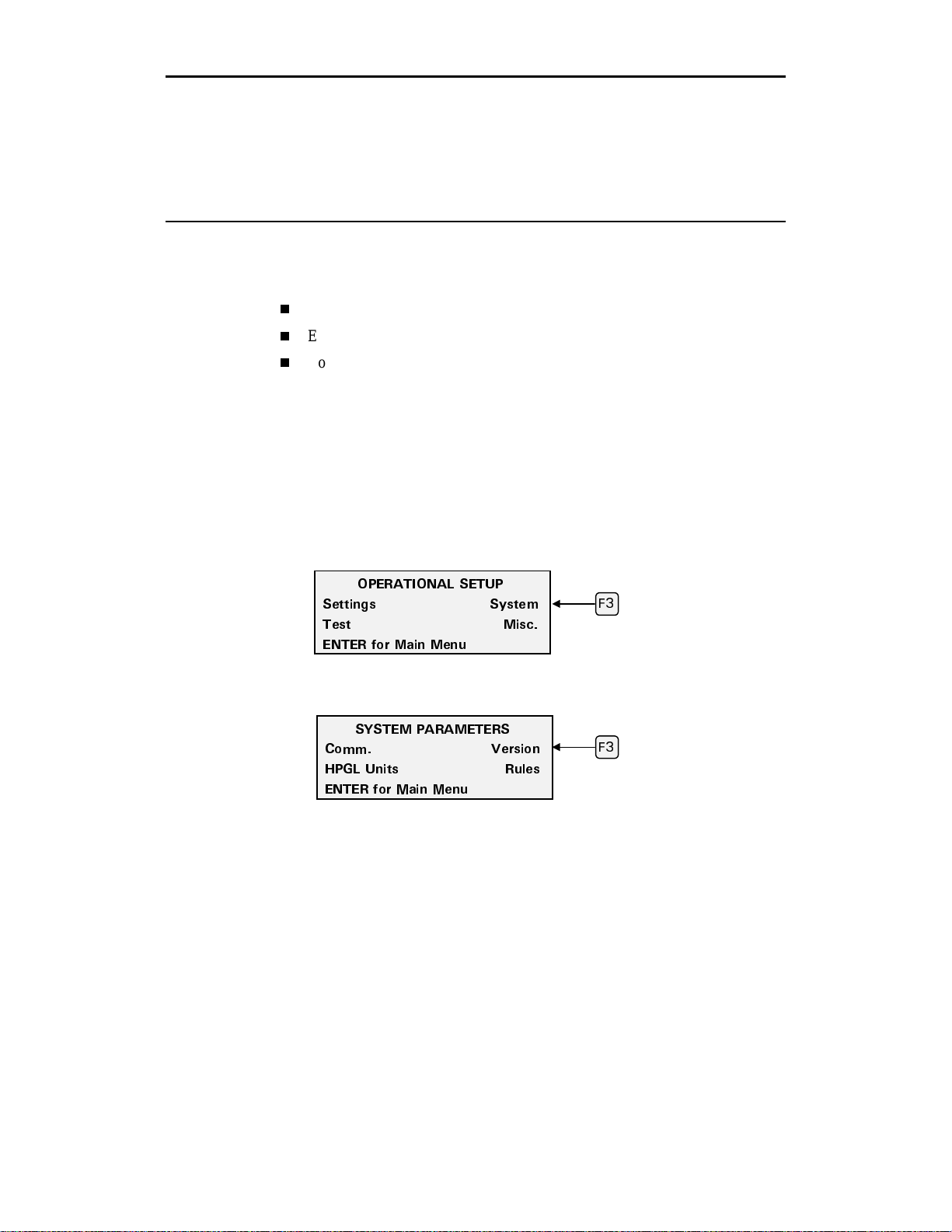
56 enVision Owner’s Guide
Troubleshooting
Your enVision plotter will provide you with troub le- free operation and
productivity for many years to come. However, if you experience an unexpected
or unusual sequence of events, use this section to address:
Version number
Error Conditions
Common Problems/Solutions
Version number
Should a problem occur you may be asked to check the firmware version
number. Perform the following steps to view your current version number.
1. Press F3 while holding down the ENTER key for the Op er ationa l Setup
menu.
2. Press F3, SYSTEM.
12'4#6+10#. 5'672
5GVVKPIU 5[UVGO
6GUV /KUE
'06'4 HQT /CKP /GPW
3. Press F3, VERSION.
5;56'/ 2#4#/'6'45
%QOO 8GTUKQP
*2). 7PKVU 4WNGU
'06'4 HQT /CKP /GPW
(
(
Page 61

Troubleshooting 57
N
4. The Version number displays. Your Gerber Field Service representative can
interpret it for you.
)GTDGT GP8KUKQP
%&%%
5RCPKUJ 8GT %
50 '
ote: This display is shown as
an example only. The display
on your plotter may be
different.
Note: There are two other ways to display the version screen.
1.
Hold down any key while the copyright message displays during power up.
Press any key to resume the power up sequence.
2.
From the MAIN MENU, press the slew up and slew down keys
simultaneously.
Error messages
The enVision plotter is programmed to detect certain mechanical/electrical error
conditions at power-up or during operation. A repetitive lo ng- short, lo ng- short
beeping pattern means that an error has been detected. When an error condition
occurs, the plotter may turn off power to the motors. The control panel displays
"System Error" followed by an error code number. The error code numbers and
their meanings are listed below. Call Gerber Field Service at 800-828-5406 or
860-643-1515, or fax 860-645-2448
Error/Failure Meaning Correction
1 ROM Read-Only Memory has been
corrupted.
2 RAM Random-Access Memory has
been damaged.
3 Plotter Type Invalid Jumpers indicate an illegal
type of plotter.
6 MFP Failure Communication chip
malfunction.
7 Heartbeat Intr Failure Electrical control board
failure.
8 Display Failure Display not responding. Retry. Call Field Service if retry fails.
9 Encoder Zeroing Failed Encoder chip failure. Retry. Call Field Service if retry fails.
10 X Axis Wiring Failure Correct X axis wiring. Contact Field Service.
11 Y Axis Wiring Failure Correct Y axis wiring. Contact Field Service.
12 Z Axis Wiring Failure Correct Z axis wiring. Contact Field Service.
13 X Axis Encoder Failure Check X axis encoder and
power connectors.
14 Y Axis Encoder Failure Check Y axis encoder and
power connectors.
15 Z Axis Encoder Failure Check Z axis encoder and
power connectors.
.
Contact Field Service.
Contact Field Service.
Retry. Call Field Service if retry fails.
Retry. Call Field Service if retry fails.
Retry. Call Field Service if retry fails.
Contact Field Service.
Contact Field Service.
Contact Field Service.
Page 62

58 enVision Owner’s Guide
Error/Failure Meaning Correction
16 Y Axis Encoder Failure Check encoder and power
connectors.
17 Servo System Halt SYSOK line not asserted. Contact Field Service.
18 X Axis Overload Material movement is jammed
19 Y Axis Overload Tool head motion moving left
20 Z Axis Overload Tool head moving up and
21 Axis Overload Motion is axis is jammed or
22 Bad Ctrl PCB Version Incompatible driver board. Contact Field Service.
23 Unknown Plot Data Plot data corrupted in plotter . Re-send job.
24 Plotter Overheated Temperature inside the plotter
25 Unexpected Interrupt Elec control board failure. Retry. Call Field Service if retr y fails.
26 Unknown Interrupt Elec control board failure. Retry. Call Field Service if retry fails.
27 EEPROM Failure Non-volatile memory chip not
28 X Axis Home Error Axis cannot move to home Remove any obstacles to axis
29 Y Axis Home Error position due to excessive movement. Retry. Call Field Service
30 Z Axis Home Error friction or obstruction. if retry fails.
31 Comm Data Overflow
Error
32 Comm Overflow Error incompatible compatibility with computer.
33 Comm Parity Error communication settings.
34 Comm Framing Error
or obstructed.
and right Motion is jammed or
obstructed.
down is jammed or
obstructed.
obstructed.
is too hot.
functioning.
Invalid, illegal, or Check communication setting for
Check for obstructions and retry. Call
Field Service if retry fails.
Unjam X axis. Retry. Call Field
Service if retry fails.
Unjam Y axis. Retry. Call Field
Service if retry fails.
Unjam Z axis. Retry. Call Field
Service if retry fails.
Unjam all axes. Retry. Call Field
Service if retry fails.
Power off, let cool. Power on. Check
for running fan and clear air vents.
Power on holding F1 and CANCEL
keys to load factory defaults. Retry.
Call Field Service if retry fails.
Page 63

Troubleshooting 59
Common problems/solutions
This chart of symptoms can help identify the possible problem and the probable
adjustment procedure. Refer to the table below for help when solving a problem.
Symptom Recommended Procedure
No power Check power cable, plugs, fuses, and the ON/OFF switch.
Missing tool You can choose to ignore the warning without
consequences. The warning occurs only once. After the
warning, the plotter waits for you to start the job again to
allow you to cancel the job (if required) or insert a tool.
Verify that the tool is properly loaded.
Poor cut quality Check knife settings (speed, force, acceleration, and
corners). Knife blade (chipped, cracked, or worn). Too
much or too little blade exposed. Check X axis cutting strip.
“Job Clipped” message Check the start point of the tool head. When a job is
clipped, there is not enough room to run the job. Job
clipping occurs with 16 bit applications that have
insufficient Y axis room due to a mis-position e d tool head
start point.
Job Paused and will not restart Make sure that the cover is fully closed. Partial job may
have been sent. Clear the job and resend.
Material jams Be sure the vinyl holes are on the sprocket pins correctly.
Clean sprockets. Make sure that sufficient space has been
provided for the material to flow (run-out) in the back and
the front of the plotter and that the material is loaded
properly.
Job not received at plotter (no
communication between
computer and plotter)
Poor performance Perform routine cleaning and lubrication. Check
Tool latch binds Apply a light coating of grease on the male part of the door
Plotter error See “Error conditions” on p. 57.
Inconsistent tool/material
contact
Thick and thin strokes Check in this order:
Jagged or serrated cutting edges Bad blade or bad tool holder.
Check the connection on the communication port, selection
of correct plotter in the design program (driver), and correct
cable.
corners/force/blade depth settings.
latch mechanism.
Check the X axis cutting strip for excessive wear.
Make sure that pouncing is turned off.
1. Material alignment in sprockets.
2. Check the position of the blade in the knife holder.
3. The knife should swivel freely and not wobble.
Page 64

60 enVision Owner’s Guide
Maintenance
This section includes instructions for routine cleaning and fuse replacement.
Routine cleaning/replacement
Routine cleaning should be done weekly or after every 80 hours of use,
whichever occurs first. Use a clean, lint-free cloth and 97% or greater isopropyl
alcohol to clean dust and debris.
Tool head
1. Remove the tool head cover by removing the two screws on top of the cover
and pulling the cover straight out.
2. Gently blow out with canned air.
Screw holes
Cables
Note: When replacing the cover, ensure that the cables are not pinched or
damaged by the cover and that the flat washers on the cover mounting screws
are outside the cover. Slide the cover to the left to avoid conta cting the tool door
area.
Page 65

Sprockets and bails
Maintenance 61
X axis material
support surface
Bail
Sprocket
1. Clean the left and right bail wheels and the bail.
2. The left sprocket assembly floats on a pin. Clean the pin so that the sprocket
floats freely.
3. Inspect the pins of the sprockets for adhesive buildup from the use of vinyl
films. Use a small stiff brush (such as a toothbrush) dipped in isopropyl
alcohol to clean the sprockets.
4. After using isopropyl alcohol to clean them, immediately dry the sprockets
and x axis material support surface with a lint-free cloth.
Page 66

62 enVision Owner’s Guide
Y axis beam and tool assembly
CAUTION: Allowing a build-up of dirt to accumulate on the metal ways
can shorten the life of the moving parts and can adversely affect cutting
quality. (The metal ways are the four shiny metal surfaces the bearings ride
on: two on the top , and two on the bottom.)
Y axis carriage
support beam
Bearings
Metal
ways
(other
bottom
one is
hidden
in this
view)
CAUTION: Do not place any alcohol on the bearings. Clean bearings with
a lint-free cloth.
1. Keep the Y axis beam free of dirt and debris by periodically wiping down
with a lint-free cloth.
2. Use a lint-free cloth and isopropyl alcohol to clean any dust or debris from
the metal ways. Pay particular attention to any surface that has bearings in
the tracks and bearings underneath and behind a track on the axis beam.
3. Move the carriage to clean the full length of the metal ways.
Page 67

Material support
There are two areas that support material: one on the rear of the plotter and one
on the front. The supporting area on the front contains a cut off mat for cutting
off material. Clean this mat with a lint-free cloth and isopropyl alcohol.
Cleaning/replacing the cutting strip
Maintenance 63
Stripper plate
cut off mat
Stripper plate
The cutting strip is the plastic strip running the length of the plotter. It provides a
reliable cutting surface and prevents the knife blade from cutting into the metal
surface. Clean it with a lint free cloth and isopropyl alcohol. Replacement strips
can be purchased from your distributor. Follow the procedures below to replace
the cutting strip.
1. Remove the worn cutting strip by lifting it up at one end and pulling it
straight up together with the underlying adhesive.
2. Clean the exposed surface with alcohol to remove any adhesive where the
strip was attached.
Page 68

64 enVision Owner’s Guide
A
3. Remove the protective backing from the replacement strip and insert it into
the groove.
4. Press the cut strip firmly along its entire length to assure tight, even
adhesion. The strip must be flat for the entire length.
Fuse replacement
The enVision has both AC and DC fuses. Refer to these procedures to replace
fuses.
AC fuse replacement
WARNING: Turn off the power switch and disconnect the power cord
from the power supply.
The AC fuse is located in the AC power inlet connection on the rear pan e l wh ere
the AC cord plugs into the unit. When this fuse is blown there is no power
supplied to the plotter, nothing appears in th e display area and the fan will not be
on.
C fuse replacement
1. Unscrew and remove the serial cable from the rear panel of the enVision.
2. Remove the plotter power cord from the socket.
Page 69

3. Find the small tab at the right edge of the fuse carrier just to th e lef t of th e
power cord receptacle. Insert a flat-tip screwdriver under the tab and gently
pry outward, loosening the carrier.
4. Pull out the fuse carrier.
5. Remove any blown fuse. The fuse rating is marked on the fuse itself. Be
sure to replace a blown fuse with a new fuse of identical size and rating.
Reinsert the carrier the same way it came out and press it firmly into place.
6. Reinstall the power cord and serial cable, and turn on the power at the
plotter.
DC fuse replacement
WARNING: Turn off the power switch and disconnect the power cord
from the power supply.
When the DC fuse is blown the enVision displays a System Error 17. The DC
fuse holders are located on the back panel of the enVision and look like two
rounded slotted (black) caps.
Maintenance 65
1. Turn off the unit and unplug the power cord.
Page 70

66 enVision Owner’s Guide
2. Insert a flat tipped screwdriver into slotted cap , as shown in the illustration,
and rotate counterclockwise about ½ turn. Cap will release spring outward.
3. Take out cap and remove fuse.
4. Remove any blown fuse. The fuse rating is marked on the fuse itself. Be
sure to replace a blown fuse with a new fuse of identical size and rating.
5. Replace cap and using a flat tip screwdriver press inward until flush with
the carrier.
6. Turn ½ turn clockwise.
Page 71

67 enVision Owner’s Guide
HPGL Support
This appendix provides the HPGL commands supported by the enVision. It also
describes a test file you can use to verify enVision operation.
The default HPGL plotter unit for the enVision plotter is 0.01mm (0.0003937
inch). To change it to 0.025 mm (0.0009843 inch), follow the procedure in
“Changing the HPGL units” on page 69.
HPGL command set
The following are HPGL commands that will be recognized by the enVision
plotter.
DF
- Set HPGL defaults
IN
- Initialize tool settings
OE
; - Output Error (first error) Responds with one number: 0= no error, 1=
unknown command, 2= wrong number of parameters for command, 3=
parameter out of range, 6= parameter value overflow, 7= data buffer overflow.
OH
; - Output Hardware travel limits (X
numbers (0.005mm per unit) separated by commas: example for enVision 750
0,0,9144000,138430
OI
; - Output Identification string
OS
; - Output Status of plotter. Responds with one DECIMAL number whose
hexadecimal bit pattern is: Bit 0= 0 if tool is up, 1 if tool is down; Bit 1 and Bit
2 are always 0; Bit 3 is 1 if this is the first OS; command received since the last
IN; command, else it is 0; Bit 4 is always 1; Bit 5 is 1 if an error exists (see OE;
command); Bits 6 and 7 are always 0;
Bit # 7 6 5 4 3 2 1 0
Value 0 0 Error 1 1st OS? 0 0 Down
PA
- Pen Absolute coordinates
PR
- Pen Relative coordinates
min,Ymin,Xmax,Ymax
). Responds with four
Page 72

68 enVision Owner’s Guide
PU
- Pen Up move
PD
- Pen Down move
PG
; - Page (End of Job) This command is used as the end-of file marker.
Failure to use the page command could result in the job stopping with the pen
down or successive jobs overcutting an earlier o ne.
SP
- Set Pen type (2 = pen plot, other = cut)
VS
- Speed Set (in cm/sec)
HPGL test file
The following procedures will guide you through plotting a one-inch box. This
test assures you that your system is communicating with the enVision plotter.
1. Use a plain text editor, such as Notepad, and create the following text.
IN;
SP1; (knife) Pen= SP2;
PU0,0;
PD0,2540,2540,2540,0,0;
PU2794,0;
PG;
Note: There should not be any character in the file after the semicolon
following PG.
2. Save the file as HPGLTEST.TXT
3. Place your computer in DOS mode.
4. Set the port parameters using mode command.
MODE COMx:9600,n,8,1,p
(where x is the COM port number)
5. Copy the test file to the COM port.
COPY HPGLTEST.TXT COMx:
(where x is the COM port number)
Page 73

6. Press F1 to Start the job.
/#+0 /'07
(
5VCTV,QD 5GVVKPIU
/QFG 5KPING *QOG
,QD 5VCVWU 4GCF[
Each time the file is sent to the plotter it should plot a one-inch square and
advance .1 inch.
Changing the HPGL units
The enVision is factory set with an HPGL unit of 0.010 mm. You can change it
to 0.025 mm by following this procedure.
1. Press F3 while holding down the ENTER key for the Op er ationa l Setup
menu.
2. Press F3, SYSTEM.
12'4#6+10#. 5'672
5GVVKPIU 5[UVGO
6GUV /KUE
'06'4 HQT /CKP /GPW
Index 69
(
3. Press F2, HPGL Units.
5;56'/ 2#4#/'6'45
%QOO 8GTUKQP
(
*2). 7PKVU 4WNGU
'06'4 HQT /CKP /GPW
4. Press F3 and F4 to toggle between 0.025 mm and 0.010 mm.
5'.'%6 *2). 70+65
7PKVU 5K\G
OO
'06'4 -G[VQ #EEGRV
(
(
5. Press ENTER to accept the selected value. Press ENTER again to return to
the MAIN MENU.
Page 74

70 enVision Owner’s Guide
Index
A
Acceleration.........................................40, 45
Adjusting
corners.................................................. 32
force...................................................... 30
Autofit ...................................................... 26
B
Bail handles.............................................. 11
Baud rate .................................................. 48
C
Cancel key.................................................. 8
Canceling a job......................................... 26
Center Target check box........................... 20
Cleaning, routine...................................... 61
Communication settings........................... 48
Connecting to the computer........................ 4
Control panel.............................................. 7
Conventions................................................ 2
Corners..................................................... 40
adjusting ..........................................32, 33
cut quality............................................. 32
setting ................................................... 44
Customer support ....................................... 2
D
Data bits.................................................... 48
Default
restoring for selected material .............. 28
settings 47, 48
E
EDGE
eyepiece................................................ 12
using Center Target check box............. 20
using Plotter Prompts check box.......... 20
using with the plotter............................ 20
Enter key..................................................... 8
Error messages.......................................... 57
F
Force................................................... 40, 42
adjusting.......................................... 30, 31
Function keys.............................................. 8
Fuses, replacing ........................................ 65
G
GA
pouncing ............................................... 37
software, loading.....................................6
using with the plotter............................ 19
H
Home feature ............................................ 10
HPGL
changing units....................................... 70
support..................................................68
test file .................................................. 69
I
Installing tools .......................................... 12
J
Job
cancelling..............................................26
clipped message.................................... 26
pausing.................................................. 25
pouncing ............................................... 37
repeats................................................... 34
restarting...............................................25
status.....................................................21
test......................................................... 50
K
Knife
adjusting blade exposure.......................12
blade, changing..................................... 15
blades, compensating for wear.............. 29
offset....................................... See corners
tool........................................................ 12
L
Loading material......................................... 9
Fine tuning the plotter .............................. 29
Page 75

Index 71
M
Maintenance ............................................. 61
Manual conventions.................................... 2
Material
loading.................................................... 9
overriding rule sets............................... 41
pull-down.............................................. 36
selecting................................................ 18
selecting on plotter ............................... 28
Menus......................................................... 7
Message display.......................................... 8
Mode
multi...................................................... 23
single .................................................... 22
Multi mode............................................... 23
automatic starting ................................. 25
O
Offset.......................................... See corners
P
Parity ........................................................ 48
Pausing a job ............................................ 25
Pen tool..................................................... 12
Phone numbers........................................... 2
Plotter
advance functions................................. 34
cleaning ................................................ 61
connecting to computer .......................... 4
default settings.................................47, 48
features ................................................. 17
fine tuning............................................. 29
fuses, replacing..................................... 65
installing tools ...................................... 14
material loading...................................... 9
material pull-down................................ 36
pouncing............................................... 37
pouncing from ...................................... 38
selecting materials................................ 28
setting up ................................................ 3
software setup......................................... 5
testing ................................................... 50
tool settings........................................... 18
tools...................................................... 12
troubleshooting..................................... 56
turning on ............................................... 5
using with GA....................................... 19
using with the EDGE............................ 20
version number.....................................56
Plotter Prompts check box........................ 20
Plotter Settings dialog box........................19
Plotting
a single job............................................ 22
jobs........................................................21
multiple jobs ......................................... 23
Pouncing................................................... 37
from GA................................................ 37
from the plotter.....................................38
turning off............................................. 39
Problems and solutions............................. 59
R
Repeating a job.........................................34
Restarting a job......................................... 25
Rule sets.................................................... 18
overriding..............................................41
S
Select Rule Usage menu...........................20
Setting tool force.......................................30
Setting up software for the plotter .............. 5
Settings menu............................................28
Single mode.............................................. 22
Slew keys.................................................... 8
Software
GA setup................................................. 6
plotter setup ............................................ 5
Speed .................................................. 40, 46
Starting a job............................................. 22
automatically in Multi mode................. 25
Stop bits.................................................... 48
T
Telephone numbers..................................... 2
Test jobs.................................................... 50
Tools
acceleration, setting .............................. 45
adjustment ranges ................................. 40
customizing settings..............................42
force, setting .............................29, 30, 42
head, positioning................................... 26
installing ......................................... 12, 14
missing message................................... 27
settings...................................... 18, 28, 40
settings defined..................................... 40
Page 76

72 enVision Owner’s Guide
speed, setting ........................................ 46
viewing settings .................................... 42
Troubleshooting........................................ 56
U
Unpacking .................................................. 3
Use Settings check box............................. 19
V
Version number........................................ 56
Vinyl strip, replacing................................64
W
Wagon wheel test job................................51
canceling............................................... 52
Web site address.........................................2
X
X08 test job............................................... 53
canceling............................................... 55
Page 77

g
default
(
g
)
y
Corners
s Menu
Settin
Multi Mode
Main Menu
Normal Plotter Operations
Force
Material
enVision™ Menu Tree
Single Mode
assisted by Gerber service personnel
= menus to be accessed only when being
Advanced Plotter Operations
Version Rules
down ENTER
Press F3 while holdin
Setup
Operational
Settings
Current
Velocity Accel Force Offset
Test menu
X08-Cut Wheel-Pen Disable
Test Jobs
System
Misc. Settings
HPGL Units
Communications
Data Bits Baud Stops Parit
Repeats Pulldown Pounce Default
Page 78

enVision Owner’s Guide
t
COMMENT CARD
Please take a moment to complete this questionnaire and mail it to Gerber Scientific Products or fax it to
860-648-8214. We are working hard to produce documentation that will meet your needs. We value your
comments.
First Name: _____________________ Last Name: ___________________________________________
Company: _____________________________________________ Phone: _______________________
Street Address:____________________________________________City: _______________________
State/Province:___________________Country: _________________Zip/Postal Code: ______________
0123456
( ) ( ) ( ) ( ) ( )
1. How many years of experience do you
have with devices of this type?
2. How often do you refer to the manual?
3. How easy was it to use?
4. Did you learn what you needed to know?
5. Was the manual well organized?
6. Was the manual clearly written?
7. Were there enough illustrations?
8. Did the illustrations support the
procedures?
9. What is your overall rating of the manual?
none
never
difficul
no
poorly organized
not clear
not enough
no
poor
( ) ( ) ( ) ( ) ( )
( ) ( ) ( ) ( ) ( )
( ) ( ) ( ) ( ) ( )
( ) ( ) ( ) ( ) ( )
( ) ( ) ( ) ( ) ( )
( ) ( ) ( ) ( ) ( )
( ) ( ) ( ) ( ) ( )
( ) ( ) ( ) ( ) ( )
over 5 yrs experience
frequently
easy
yes
very well organized
very clear
enough
yes
excellent
10. How many people work in your shop?
Additional comments on the manual:
________
________________________________________________________
______________________________________________________________________________________
______________________________________________________________________________________
______________________________________________________________________________________
______________________________________________________________________________________
______________________________________________________________________________________
______________________________________________________________________________________
______________________________________________________________________________________
______________________________________________________________________________________
______________________________________________________________________________________
______________________________________________________________________________________
P67606A Rev B
Page 79

BUSINESS REPLY MAIL
FIRST CLASS PERMIT NO. 001 South Windsor, CT
POSTAGE WILL BE PAID BY ADDRESSEE
ATTN: TECHNICAL COMMUNICATIONS DEPARTMENT
Gerber Scientific Products, Inc.
83 Gerber Road
South Windsor, CT 06074-9864
NO POSTAGE
NECESSARY
IF MAILED
IN THE
UNITED STATES
Page 80

P67606A Rev B
151 Batson Drive Manchester, CT 06040
U S A
 Loading...