

Page 1

Copyright Notice
COPYRIGHT 2006 Gerber Scientific International. All Rights Reserved.
This document may not be reproduced by any means, in whole or in part, without written permission of
the copyright owner.
This document is furnished to support the ART Path and Auto-CarveUser’s Guide. In consideration of
the furnishing of the information contained in this document, the party to whom it is given assumes its
custody and control and agrees to the following:
1. The information herein contained is given in confidence, and any part thereof shall not be copied or
reproduced without written consent of Gerber Scientific International.
2. This document or the contents herein under no circumstances shall be used in the manufacture or
reproduction of the article shown and the delivery of this document shall not constitute any right or
license to do so.
Information in this document is subject to change without notice.
PrintedinUSA
GSP is a registered trademark,and ART Path,Auto-Carve,Sabre, Dimension, and OMEGAare trademarksof GerberScientific
Products,Inc. HPGLis a trademark of Hewlett-PackardCompany. Rowmark is a registeredtrademarkof Rowmark,Inc. Microsoftand
Windows are registeredtrademarks of Microsoft Corporationin the US and other countries.
Page 2

FCC NOTICE
WARNING This is a Class A product. In a domestic environment this product may cause radio
interference in which case the user may be required to take adequate measures.
This equipment has been tested and found to comply with the limits for a Class A digital device,
pursuant to Part 15 of the FCC rules. These limits are designed to provide reasonable protection against
harmful interference when the equipment is operated in a commercial environment. This equipment
generates, uses, and can radiate radio frequency energy and, if not installed and used in accordance with
the instruction manual, may cause harmful interference to radio communications. Operation of this
equipment in a residential area is likely to cause harmful interference in which case the user will be
required to correct the interference at his own risk.
This digital apparatus does not exceed the Class B limits for radio noise emissions from digital apparatus
set out in the Radio Interference Regulationsof the Canadian Department of Communications.
Le present appareil numerique n'emet pas de bruits radioelectriques depassant les limites applicables aux
appareils numeriques de la classe B prescrites dans les Reglements sur le brouillage radioelectrique edicte
par le Ministere des Communications du Canada.
Page 3

Book One: I ntroducti on to ART Path.................................................................................. 1
Chapter 1 : Setting up ART Pa th........................................................................................... 3
Unpacking/Installation.................................................................................................................... 3
Systemrequirements ........................................................................................................................ 3
Installing the ART Path software option......................................................................................... 4
Accessing ART Path.......................................................................................................................... 4
Customer Support.............................................................................................................................5
Chapter 2 : Reviewing t he AR T Pa th Toolbox..................................................................... 7
CancelSelect...................................................................................................................................... 7
Pointer................................................................................................................................................ 7
Zoom.................................................................................................................................................. 8
Unzoom............................................................................................................................................. 8
Male................................................................................................................................................... 9
Male Auto Inlay Parameters........................................................................................................ 10
Female.............................................................................................................................................. 12
Female Auto-Inlay Parameters.................................................................................................... 13
Engrave............................................................................................................................................ 15
Engraving Channel Cut Parameters........................................................................................... 15
Cleanout........................................................................................................................................... 16
Direction....................................................................................................................................... 18
Auto-Inlay Parameters................................................................................................................. 19
Use Diagonals............................................................................................................................... 19
Drill .................................................................................................................................................. 20
Nesting............................................................................................................................................. 21
HorizontalCutline.......................................................................................................................... 22
Move Cutline................................................................................................................................... 22
Auto-Carve 3D................................................................................................................................ 23
Prismatic ...................................................................................................................... .................... 23
Set Start Point.................................................................................................................................. 23
Book Two: Menus and Proc edures................................................................................... 25
Chapter 3 : File Menu........................................................................................................... 27
New.................................................................................................................................................. 27
Open................................................................................................................................................. 27
Close................................................................................................................................................. 27
Save.................................................................................................................................................. 28
Save As ............................................................................................................................................ 28
Save Plot File................................................................................................................................... 29
Save to Spool File............................................................................................................................ 29
Save Parameters.............................................................................................................................. 30
Place................................................................................................................................................. 30
Library............................................................................................................................................. 31
Print................................................................................................................................................. 31
Print Setup....................................................................................................................................... 31
Recently Used File list..................................................................................................................... 31
Exit................................................................................................................................................... 31
Page 4

Chapter 4 : Edit Menu...........................................................................................................33
Undo................................................................................................................................................ 33
Cut.................................................................................................................................................... 33
Copy and Paste................................................................................................................................ 33
Pastefrom Composer................................................................................................................... 34
PasteBack..................................................................................................................................... 35
Delete......................................................................................................................... ...................... 35
SelectAll.......................................................................................................................................... 35
Reverse Select.................................................................................................................................. 35
SelectOpen Shapes......................................................................................................................... 35
SelectUnused Shapes..................................................................................................................... 36
Chapter 5 : Shape Menu......................................................................................................37
Repeats............................................................................................................................................. 37
Repeats dialog box....................................................................................................................... 37
Sizing Shapes................................................................................................................................... 38
Percent Size dialogbox ........................................................................................................... ..... 39
Absolute Size dialogbox............................................................................................................. 40
Join................................................................................................................................................... 41
Group............................................................................................................................................... 42
Ungroup .......................................................................................................................................... 42
Layer................................................................................................................................................ 42
SmartEdit Layer........................................................................................................................... 43
Chapter 6 : Setup M e nu.......................................................................................................45
Tool Edit.......................................................................................................................................... 45
Tool InformationDialogBox....................................................................................................... 45
Tool Edit Dialog Box.................................................................................................................... 46
Start/End Position.......................................................................................................................... 48
RouterSelection.............................................................................................................................. 50
Use Material.................................................................................................................................... 50
Material Size.................................................................................................................................... 51
Nesting Setup.................................................................................................................................. 52
Join Tolerance.................................................................................................................................. 52
Show Tool ChangerPosition.......................................................................................................... 53
Chapter 7 : Tool Pa th Menu................................................................................................55
Tools Used....................................................................................................................................... 55
Organize Tool Order dialog box................................................................................................. 55
Engrave............................................................................................................................................ 56
Male................................................................................................................................................. 56
Female.............................................................................................................................................. 56
Cleanout........................................................................................................................................... 57
Drill .................................................................................................................................................. 57
Toolpath Dialog Boxes.................................................................................................................... 58
Understanding the Tool path...................................................................................................... 58
Setting Tool path parameters.......................................................................................................58
Applying additional features......................................................................................................... 61
Using tool path templates............................................................................................................ 61
Applying a finish cut ................................................................................................................... 63
Creating an inlay.......................................................................................................................... 63
Applying climb milling................................................................................................................ 64
Page 5

Selecting Lead In/Lead Out........................................................................................................ 65
Setting the spindle speed ........................................................................................................... 65
Using the Engrave command ......................................................................................................... 65
Additional information found in the Default Engrave Info Dialog Box................................... 67
Using theMale tool path................................................................................................................. 67
Applying a male basic cut...........................................................................................................67
Applying a male finish cut ..........................................................................................................68
Applying an inlay........................................................................................................................ 69
Cuttingstencils with the Femaletool ............................................................................................. 70
Applying a Female basic cut ....................................................................................................... 70
Adding a Female finishcut......................................................................................................... 72
Adding an inlay............................................................................................................................ 73
Using Cleanout................................................................................................................................ 73
Selecting Direction....................................................................................................................... 73
Applying Use Diagonals.............................................................................................................. 74
Selecting Cleanout shapes........................................................................................................... 75
UsingDrill....................................................................................................................................... 77
Retrieving Drill symbols.............................................................................................................. 77
Generating a Drill tool path......................................................................................................... 78
Chapter 8 : Outpu t Menu..................................................................................................... 81
Job Output Dialog Box.................................................................................................................... 81
Position....................................................................................................................... .................. 82
Material Used............................................................................................................................... 82
Preposition.................................................................................................................................... 82
RouterName................................................................................................................................ 83
Job Header Message..................................................................................................................... 83
In-Place Repeats........................................................................................................................... 84
Repeats.......................................................................................................................................... 85
Plotting Parameters...................................................................................................................... 87
Tool Parameters............................................................................................................................87
Chapter 9 : Panel Menu.......................................................................................................91
HorizontalCutline.......................................................................................................................... 91
Move Cutline................................................................................................................................... 91
Panel Setup...................................................................................................................................... 92
Chapter 1 0 : View Menu.......................................................................................................95
Redraw............................................................................................................................................. 95
Toolbars and StatusBar........................................................................................................... ....... 95
Animate........................................................................................................................................... 95
ShowDry Haul Moves................................................................................................................... 96
Show Path Start Point..................................................................................................................... 96
ColorAssignments..........................................................................................................................96
Chapter 11: W indow Menu................................................................................................99
New Window.................................................................................................................................. 99
Cascade............................................................................................................................................ 99
Tile ................................................................................................................................................... 99
Arrange Icons.................................................................................................................................. 99
CloseAll .......................................................................................................................................... 99
File List ............................................................................................................................................ 99
Page 6

Chapter 1 2 : Getti n g Help in ART Path............................................................................101
Finding a topic................................................................................................................................101
Finding additionaltopics in the Topic pane..............................................................................102
Finding previously-viewed topics.............................................................................................102
Finding frequently-viewed topics..............................................................................................103
Printing topics................................................................................................................................103
Copying topics...............................................................................................................................104
Personalizing Help topics..............................................................................................................104
Displaying the ART Path version..................................................................................................104
Book Three: Intr oduc t ion to Auto- Carve........................................................................105
Chapter 13: Installing Auto-Carve...................................................................................107
SystemRequirements....................................................................................................................107
Installing ARC Station Firmware..................................................................................................108
Installing the FACS-13 Control Board...........................................................................................109
Installing the Auto-Carve Option.................................................................................................111
Chapter 14: Three-Dimensional Carving T oo ls..............................................................113
Carving Tool Sharpness.................................................................................................................114
Selecting a 3-D Tool Path Auto-Carve.....................................................................................115
Using the Default Carve Info dialog box V-Bottom.............................................................115
Default Roughing Tool InformationDialogBox.......................................................................118
Generating a 3D V bottom tool path..........................................................................................120
Using the Default Carve Info Dialog Box Flat-bottom............................................................121
Default Flat-bottom Tool InformationDialog Box....................................................................124
Generating a Flat-bottom3D tool path.........................................................................................125
Setting V-Toolparameters..........................................................................................................125
Choosing basic carving parameters...........................................................................................125
Using a roughing tool............................................................................................................. ....126
Defining Depth Limitations........................................................................................................128
Selecting Flat Bottom..................................................................................................................129
Prismatic ...................................................................................................................... ...................133
Reviewing the Default Prismatic Info dialogbox.....................................................................133
Eliminating RoughEdges...........................................................................................................136
Generating a 3-D Tool Path ......................................................................................................... ..137
SmartEditinga Tool Path..............................................................................................................137
Masking the Sign Blank.................................................................................................................138
Routing the Design........................................................................................................................139
Initializing the Router (D200 or AR600)....................................................................................139
To initializea Sabrerouter to the table ......................................................................................140
To initializea Sabrerouter to the material surface......................................................................141
Finishing the Design......................................................................................................................141
Appendix A: ART Pa th Glossary.......................................................................................143
Appendix B: Material Flat n ess.........................................................................................147
Manufactured Material..................................................................................................................147
Wood...............................................................................................................................................147
GrainType and Sawing Techniques..........................................................................................147
Moisture Content and Humidity...............................................................................................148
Shipping.......................................................................................................................................148
Page 7

Storage.........................................................................................................................................148
Carving into a Warped Panel........................................................................................................148
Appendix C: Spe e ds and Feed s for Standard R outer Motor.......................................149
Index....................................................................................................................................151
Page 8

Page 9

1
Book One:
Introduction to ART Path
ART Path32 is an OMEGA output tool that is used to link a Gerber routing system to
OMEGA programs. The Gerber routing systems listed below can be used with the ART Path
program:
♦ Sabre series 404 and 408
♦ Dimension 200
♦ ADVANTAGE R outer 600
ART Path allows you to benefit from the OMEGA Composer's design capabilities while
offering routing features such as:
♦ Climb Milling
♦ Lead In/Lead Out
♦ User-defined Tool Table
♦ Nesting Placement
♦ Drill
ART Path automatically generates tool paths for male, female, engraved, or cleanout tool paths.
It also enables automatic cutting of inlay shapes with rounded edges, use of multiple cutters
and/or depths of cut within the same job, and operator messaging while the job is being cut on
the router.
Jobs created in Composer are brought into the ART Path program where the design may be
viewed closely and nested for better positioning to conserve material.
Page 10

Page 11
3
Chapter 1:
Setting up ART Path
Unpacking/Installation
♦ If you are adding the ART Path option to your existing OMEGA release, please
continue with the instructions below (starting with the “Package contents” paragraph)
in order to install ART Path on your system.
♦ If you are upgrading to or have just purchased OMEGA, you should already have
followed the instructions in the Getting Started guide for installing OMEGA as well as
any other fonts, libraries, and options acquired, including ART Path. Refer to
documentation for your particular router if necessary for instructions on physically
connecting the router to the OMEGA system.
System requirements
Before ART Path can be installed and used, your system should be set up with the following
releases:
♦ OMEGA 2.0/2.1 with Microsoft® Windows® version 98, 2000, ME, or XP
♦ OMEGA 2.5 and higher with Microsoft Windows version 2000 or XP
To verify your OMEGA release
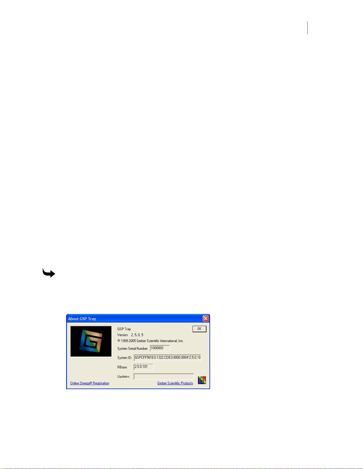
1 Right-click the GSP Tray icon that appears on the right end of the Windows s tatus bar
to open the Gerber Tray menu.
2 Click About GSP Tray. The number in the Rbase field is your OMEGA version.
3 Verify that the version listed in the Rbase field matches the software that you are
installing.
4 Click OK to return to your desktop.
Page 12
Chapter 1
4
Setting up ART Path
Installing the ART Path software option
This procedure describes loading ART Path as an option after OMEGA has been installed.
To install the ART Path software option
1 Insert the OMEGA installation CD disk into the disk drive. The OMEGA Setup Wizard
should automatically display. If it does not click Start > Run to display the Run dialog
box. Type D:\Setup.exe and click OK (Where D:\ is the drive containing the disk).
2 Click Install Products to display the Install Products menu.
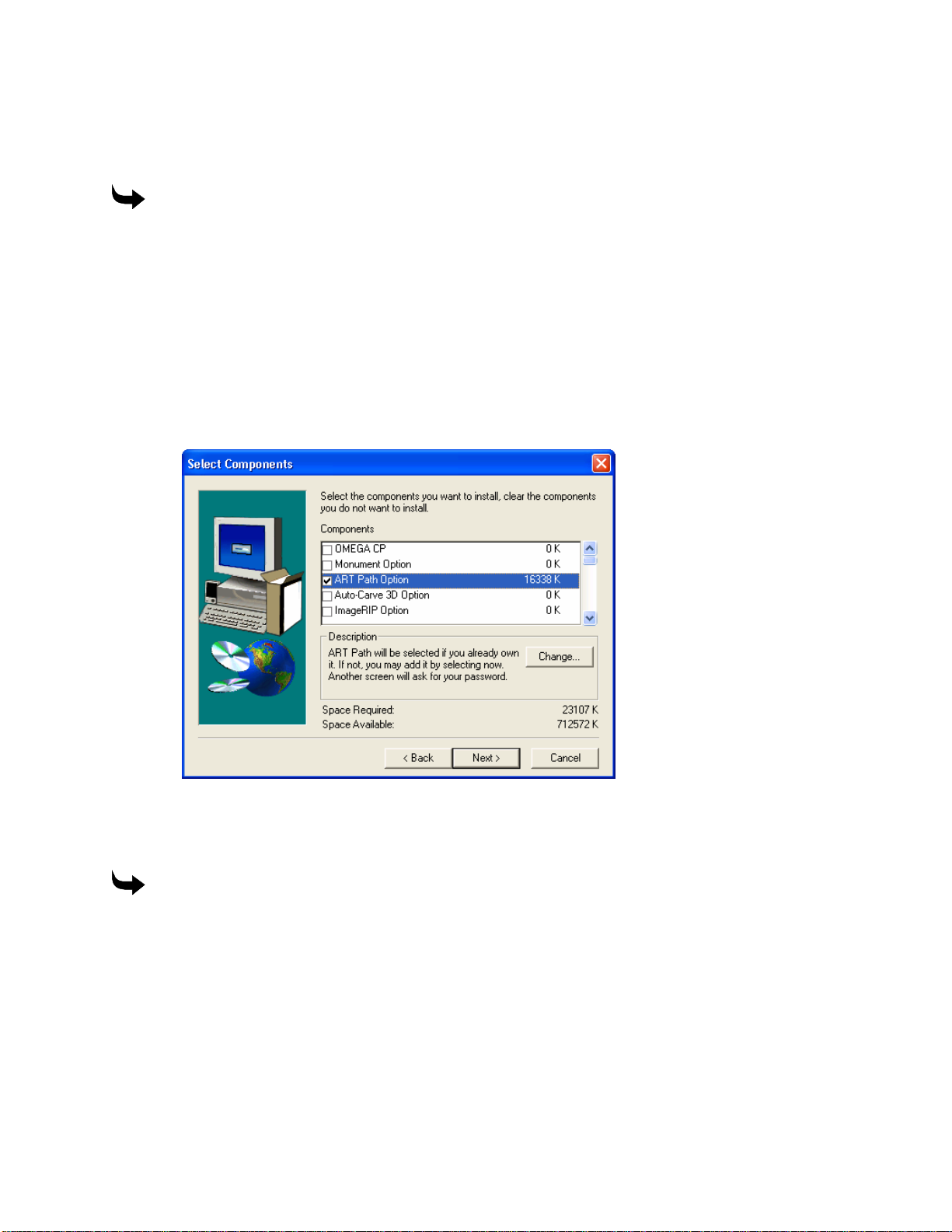
3 Click Install OMEGA 2.5. Follow the instructions until the Installation Type dialog box
displays. Choose Add/Reload Individual components and click Next.
4 At the Select Components dialog box turn on ART Path Option. If you have purchased
the Auto-Carve Option turn on this option as well. Auto-Carve requires a password to
load. Click Next to load the software.
5 When the installation completes, click Finish and restart your computer.
Accessing ART Path
To access Art Path
Click Start > Programs > GSP OMEGA > ART Path32.
Page 13

5
Customer Support
If you require assistance installing or using ART Path, contact your Gerber
!
Please use a phone that is close to your system and have the following available before calling:
If you have an OMEGA system, please have the following information ready as well:
distributororGerberTechnicalSupportat:
Phone: 860-644-6971
Fax: 860-871-3862
e-mail: gsptech@gspinc.com
♦ Microsoft Windows version numbers
♦ Systemserial number
♦ Router serial number
♦ Router User Manual
♦ OMEGA, Windows, and hardware utility CD’s.
♦ OMEGA Reference Guide
♦ The names of any peripheral (output) devices, such as a printer.
Page 14

Page 15
7
Chapter 2:
Reviewing the ART Path Toolbox
The Toolbox is located on the left side of the ART Path window. The toolbox contains tools,
which allow the user to select, zoom in, and position the shapes in a design. You can also choose
a tool path from the Toolbox.
Cancel Select
Cancel Select makes all previously selected shapes unavailable. It is useful in correcting a
selection mistake.
To deselect a shape, click on the Cancel Select Tool. The selected shape becomes deselected.
Pointer
Pointer selects and deselects a shape.
When the Pointer Tool is clicked on in the toolbox, the mouse pointer changes to a pointing
finger. The selected shape is redrawn with a solid blue line.
The Pointer Tool is also used for Smart Editing. Smart Edit allows the user to change the tool
path settings. The user returns to the specific tool path dialog box for editing the desired
parameters. A shape or design does not have to be selected first before it may be Smart Edited.
A shape must be selected with the Pointer Tool first before choosing a tool path. When using the
rubber band method of selection, the rubber band box must surround the entire shape.
To select or deselect a shape
1 Click the Pointer Tool. The mouse pointer changes to a pointing finger when moved
into the working area.
2 Move the Pointer Tool until it touches the shape and click the left mouse button. The
shape is selected and redrawn in solid blue lines. If a shape is deselected, it is redrawn
in a contrasting color.
To select or deselect multiple shapes
1 Click the Pointer Tool. The mouse pointer changes to the Pointer Tool when moved
into the working area.
2 Move the Pointer Tool to a top corner above the shapes to be selected.
3 Click and drag the tool across the shapes to the opposite corner. As the Pointer Tool is
moved, a rubber band box will be drawn around it.
Page 16
Chapter 2
8
Reviewing t h e ART Path Toolbox
4 Release the mouse button. The shapes are selected and redrawn in solid blue lines. If
shapes are deselected, they are redrawn in a contrasting color.
Zoom
Zoom magnifies a piece of a design for a closer look. When the Zoom Tool is clicked on, the
mouse pointer changes to a cross hair with a small magnifying glass shown in the lower right
corner. The design is centered and fills as much of the working area as possible after each zoom.
All tools and menu commands work on a zoomed design as on an unzoomed design. Line
lengths remain the same at every magnification.
To magnify part of a design
1 Click the Zoom Tool. The tool is highlighted. The mouse pointer changes when moved
into the working area.
2 Move the Zoom Tool to a top corner above the shape to be magnified.
3 Click and drag the Zoom Tool across the shape to be magnified. A dotted box is drawn
around the shape.
4 Click the right m ouse button. The area within the box is magnified.
5 Repeat Steps 1-4 to magnify the shape again.
Unzoom
The Unzoom Tool returns a design to its original appearance or to the previous appearance in a
series of zooms.
Unzoom remembers the appearance of the previous five zooms performed on the same design.
Clicking the left mouse button on the Unzoom Tool backtracks the working area to the previous
zoom appearance. Clicking the right mouse button on the Unzoom tool returns the design to its
original appearance before the first zoom.
Unzoom is available only after using the Zoom Tool. Only the Unzoom Tool remembers the last
five zooms. Backtracking to a sixth zoom automatically returns the design to its original
appearance.
To return a design to the previous appearance in a series of zooms
1 Click the Unzoom Tool.
2 Click the left mouse button. The magnified design redraws to its last appearance.
3 Repeat steps 1 and 2 to backtrack through each previous appearance in the series of
zooms.
Note: The design automatically returns to its original appearance on the sixth backtrack.
Page 17

9
To return a design to full size after magnifying it
Click the Unzoom Tool with the right mouse button.
Male
Male allows the user to generate a tool path to create a solid shape from the material. Clicking
on the Male Tool opens the Default Male Info Dialog Box. Refer to the “Toolpath Dialog Boxes”
section for more information. The shape must be selected before the Male Tool is available for
use.
To set male basic cut parameters
1 Select the shape to be routed with the Pointer Tool. The selected shape changes in
color to show it is selected.
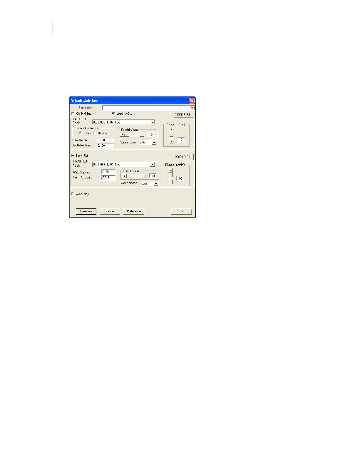
2 Click the Male Tool in the Toolbox. The Default Male Info dialog box appears on
screen.
3 In Basic Cut, click the down arrow on the right side of the Tool entry box. A drop
down list box appears.
4 Click the desired routing tool.
5 Enter the desired parameters for Total Depth, Depth Per Pass, Feed Rate, Plunge Rate,
RPM’s, Acceleration, and Surface Reference into the dialog box.
6 Click Generate, the tool path appears on screen in a contrasting color.
To set male and finish cut parameters
Note: It is important for Finish Cut to use the same tool used for Basic Cut.
1 Select the shape to be routed with the Pointer Tool. The selected shape changes in
color to show it is selected.
2 Click Male from the Tool Paths menu. The Default Male Info Dialog Box opens.
Page 18
Chapter 2
10
Reviewing t h e ART Path Toolbox
3 Click the down arrow on the right side of the Tool entry box. A drop-down list box
appears.
4 Click the desired routing tool.
5 Enter the desired Basic Cut parameters.
6 Turn on Finish Cut to display the Finish Cut parameters.
7 Click the down arrow on the right side of the Tool entry box. A drop down list box
appears.
8 Click the desired routing tool.
9 Enter the desired Finish Cut parameters for Web Amount, Finish Amount, Feed Rate
and Plunge Rate.
10 Click the 20000 R.P.M. button. The Enter Spindle Speed dialog box appears. Type the
desired speed (between 6,000 and 24,000 RPM) and click OK to close the dialog box.
11 Click Generate in the tool path information dialog box. The Basic Cut tool path and the
Finish Cut tool paths appear on screen in contrasting colors.
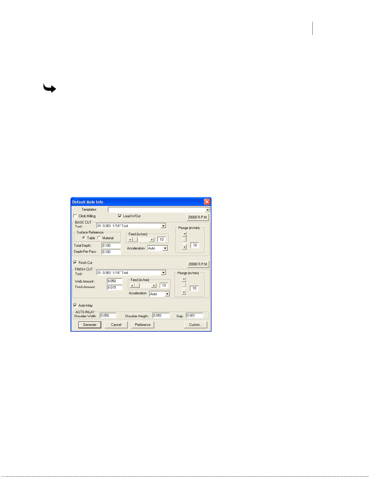
Male Auto Inlay Parameters
Auto-Inlay parameters provide information on how the two shapes (male and female) are
routed. The two auto-inlay shapes must be routed with the same tool. Auto-Inlay is an optional
parameter.
Auto-Inlay parameter values for shoulder width, shoulder height, and gap are entered when a
Shoulder is cut from the material. A Shoulder prevents light from showing through gaps
between the inlaid shapes. A Shoulder is also useful to hold letters in place. Click on the AutoInlay check box. An X appears in the check box and the Auto-Inlay parameters appear in the
dialog box.
♦ The Shoulder Width should be less than 2 or equal to the tool size. A typical shoulder
width is .125 inches (3.175mm).
Page 19
11
♦ AtypicalShoulder Height is .125 inches (3.175mm).
♦ The Gap is the amount of material that is cut between the male and female shapes. The
Gap enables the two shapes to fit together properly. A recommended gap is .005
inches (.127mm) wide.
To set male and auto-inlay paramet er s
1 Select the shape to be routed with the Pointer tool. The selected shape changes in color
to show it is selected.
2 Click Tool Path from the menu bar.
3 Click Male to display the Default Male Info Dialog Box.
4 Click the down arrow on the right side of the Tool entry box. A drop-down list box
appears.
5 Click the desired routing tool.
6 Enter the desired Basic Cut parameters.
7 Turn on Auto-Inlay to display the Auto-Inlay parameters.
8 Enter the desired parameters for Shoulder Width, Shoulder Height and Gap (see the
guidelines above for reference.) If no shoulder is desired, set shoulder width & height
to zero.
9 Click Generate in the tool path information dialog box. The Basic Cut tool path, the
Finish Cut tool path, and the Inlay Tool path appear on screen in contrasting colors.
Page 20
Chapter 2
12
Reviewing t h e ART Path Toolbox
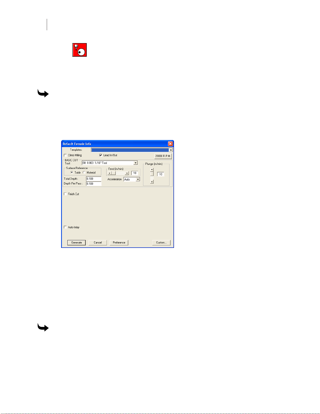
Female
Female allows the user to generate a tool path to create a stencil from the material. Clicking on
the Female Tool opens the Default Female Info Dialog Box. Refer to the “Toolpath Dialog
Boxes” section for more information. The shape must be selected before the Female Tool is
available for use.
To set female basic cut parameters
1 Select the shape to be routed with the Pointer tool. The selected shape changes in color
to show it is selected.
2 Click Tool Path from the menu bar.
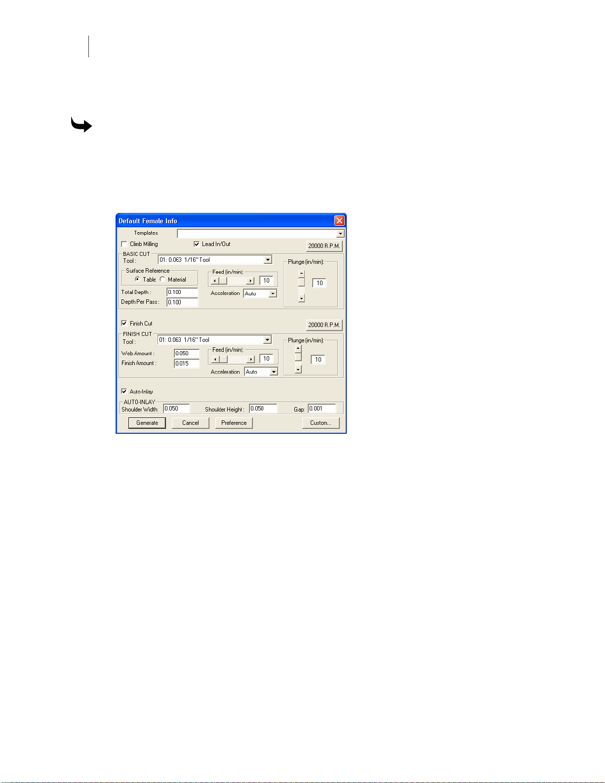
3 Click Female to display the Default Female Info Dialog Box.
4 Click the down arrow on the right side of the Tool entry box. A drop down list box
appears.
5 Click the desired routing tool.
6 Enter the desired parameters for Total Depth, Depth Per Pass, Feed Rate, Surface
Reference, RPM’s, Acceleration and Plunge Rate into the dialog box.
7 Click the 20000 R.P.M. button. The Enter Spindle Speed dialog box appears. Type the
desired speed (between 6,000 and 24,000 RPM) and click on OK to close the dialog box.
8 Click Generate. The tool path appears in a contrasting color.
To set female and finish cut parameters
1 Select the shape to be routed with the Pointer Tool. The selected shape changes in
color to show it is selected.
2 Click Tool Path from the menu bar.
3 Click Female to display the Default Female Info Dialog Box.
Page 21
13
4 Click the down arrow on the right side of the Tool entry box. A drop-down list box
appears.
5 Click the desired routing tool.
6 Enter the desired Basic Cut parameters.
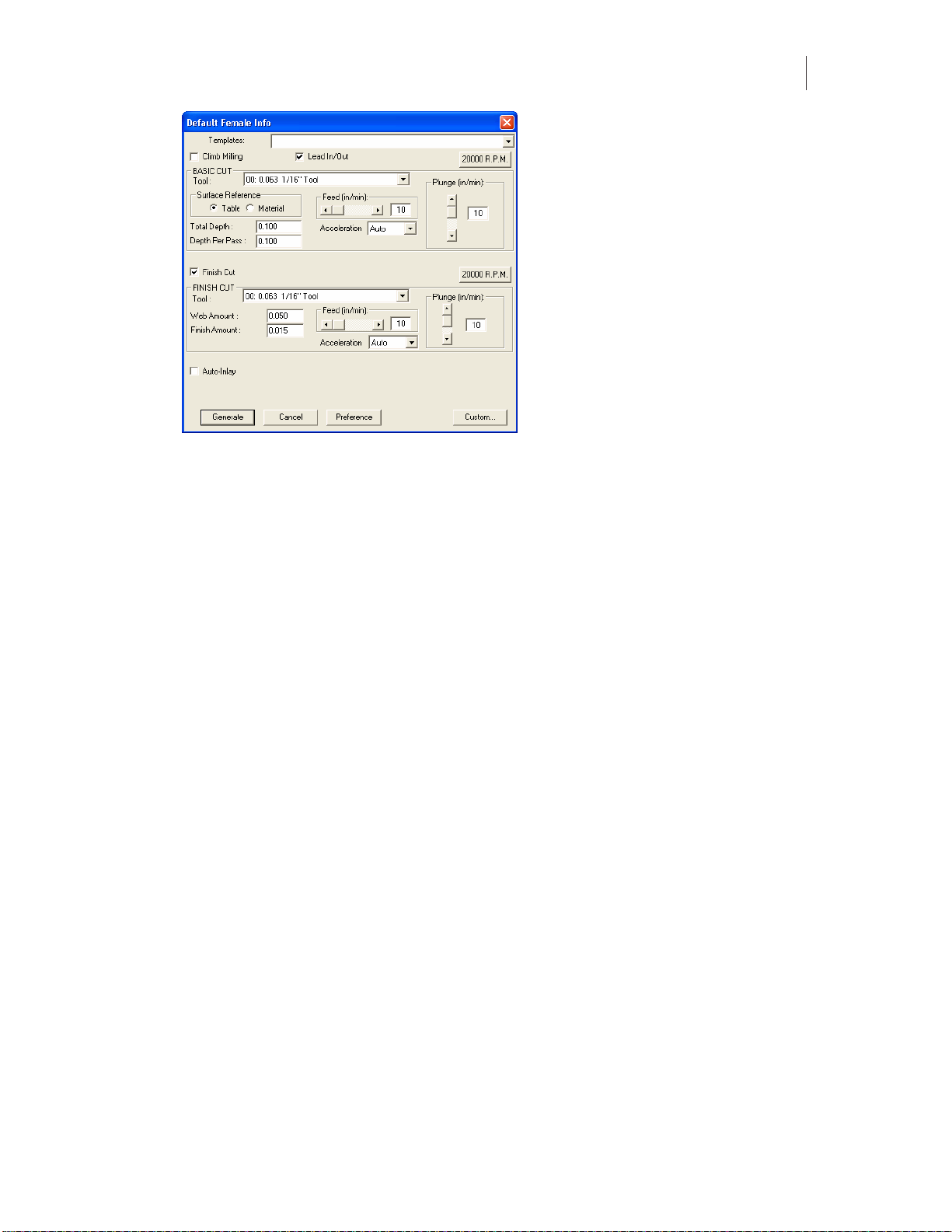
7 Click the Finish Cut check box, an X appears in the check box. The Finish Cut
parameters appear on screen.
8 Click the down arrow on the right side of the Tool entry box. A drop down list box
appears. Choose the same tool that was used for the Female Basic Cut.
9 Click the desired routing tool.
10 Enter the desired Finish Cut parameters for Web Amount, Finish Amount, Feed Rate
and Plunge Rate.
11 Click the 20000 R.P.M. button. The Enter Spindle Speed dialog box appears. Type the
desired speed (between 6,000 and 24,000 RPM) and click on OK to close the dialog box.
12 Click Generate in the tool path information dialog box. The Basic Cut tool path and the
Finish Cut tool paths appear on screen in contrasting colors.
Female Auto-Inlay Parameters
The Auto-Inlay parameters are used when a Shoulder is cut from the material. The purpose of a
Shoulder is to prevent light from showing through gaps between the inlaid shapes. A Shoulder
is also useful to hold letters in place. Click on the Inlay check box. An X appears in the check
box. The Auto-Inlay parameters appear in the dialog box.
♦ The Shoulder Width should be less than the tool size. A typical shoulder width is .125
inches (3.175mm).
♦ Atypicalshoulder height is .125 inches (3.175mm).
Page 22
Chapter 2
14
Reviewing t h e ART Path Toolbox
♦ The Gap is the amount of material that is cut between the male and female shapes. The
Gap enables the two shapes to fit together properly. A recommended gap is .005
inches (.127mm) wide.
To set female auto-inlay parameters
1 Select the shape to be routed with the Pointer Tool. The selected shape changes in
color to show it is selected.
2 Click Tool Path from the menu bar.
3 Click Female to open the Default Female Info Dialog Box.
4 Click the down arrow on the right side of the Tool entry box. A drop-down list box
appears.
5 Click the desired routing tool.
6 Enter the desired Basic Cut parameters.
7 Click the Auto-Inlay check box an X appears in the check box. The Auto-Inlay
parameters can be entered.
8 Enter the desired Auto-Inlay parameters for the Shoulder Width, Shoulder Height and
Gap (see the guidelines above for reference.) If no shoulder is desired, set shoulder
width & height to zero.
9 Click Generate. Both the Auto-Inlay tool path and the Basic Cut tool path appear on
screen in contrasting colors.
Page 23
15
Engrave
The Engrave Tool etches a design into the material on the shape's contour without using an
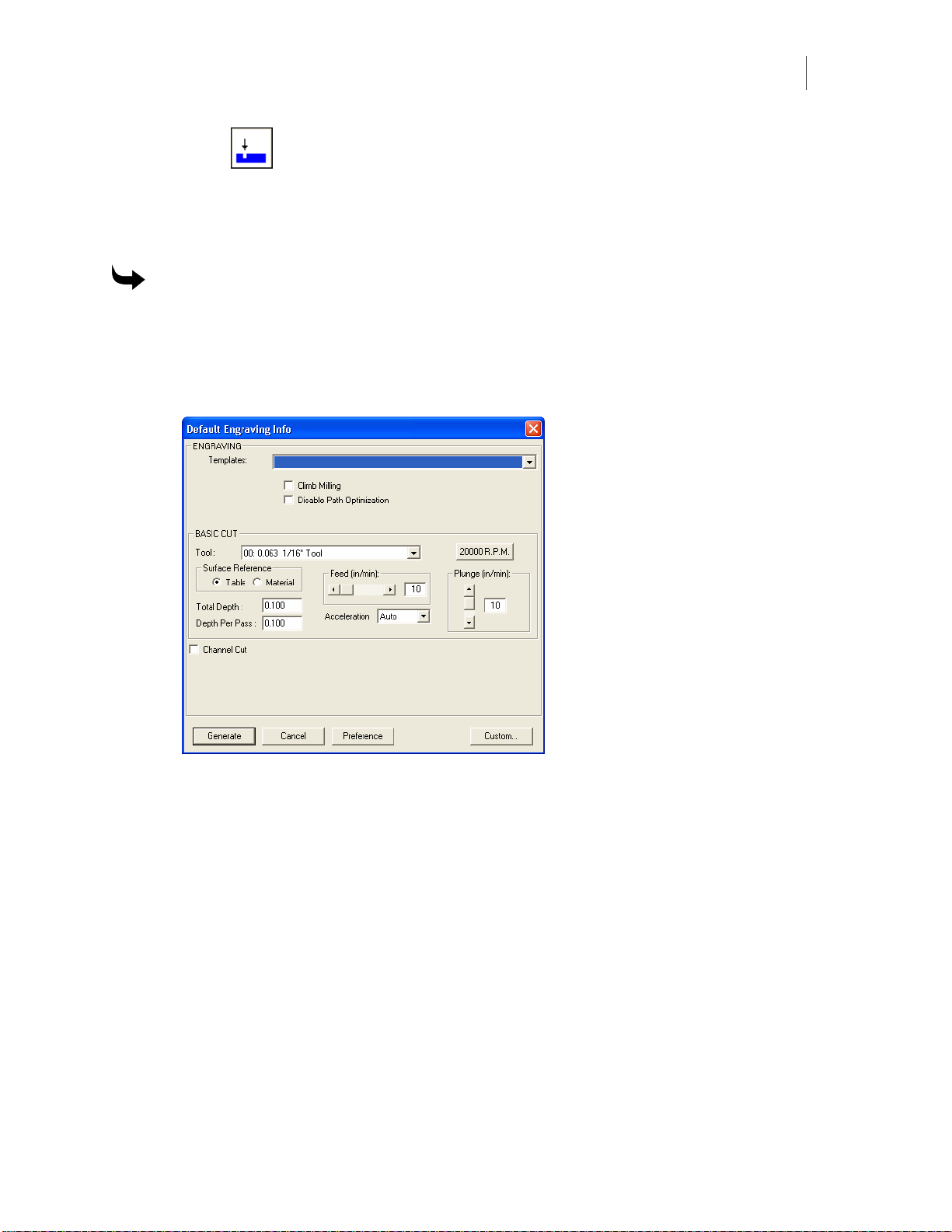
offset. Clicking on the Engrave Tool opens the Default Engrave Info Dialog Box. Refer to the
section “Toolpath Dialog Boxes” for more information. The shape must be selected before the
Engrave Tool is available for use.
To set engraving parameters
1 Select the shape to be routed with the Pointer Tool. The selected shape changes color
to show it is selected.
2 Click Tool Path from the menu bar.
3 Click Engrave. The Default Engraving Info dialog box appears on screen.
4 Click the down arrow on the right side of the Tool entry box. A drop-down list box
appears.
5 Click the desired Engraving Tool.
6 Enter in the desired parameters for Total Depth, Depth Per Pass, Surface Reference,
Acceleration, RPM’s and Plunge Rate into the dialog box.
7 Click Generate to set the tool path. The tool path appears on screen in a contrasting
color.
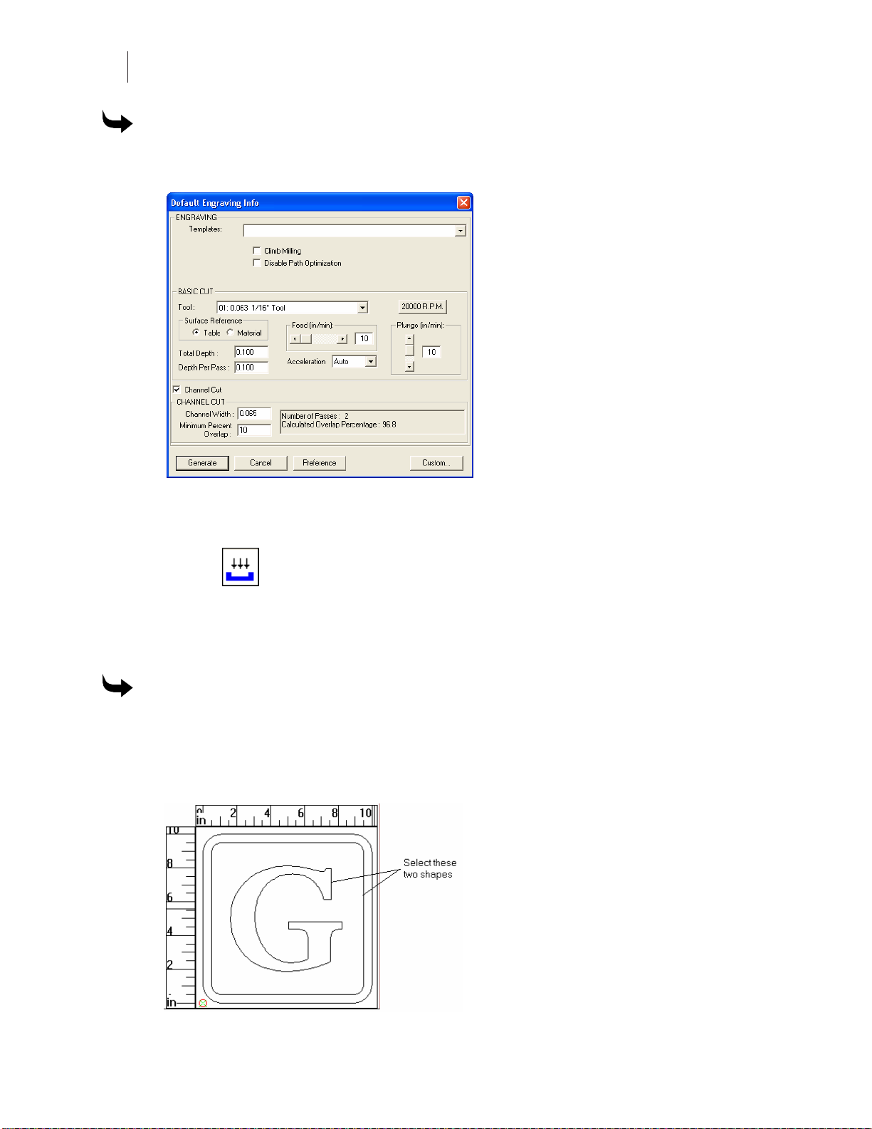
Engraving Channel Cut Parameters
The Channel Cut featuregenerates tool paths for channels whose width is larger than the
diameter of the available cutters. Turn on Channel Cut and set the stroke width. ART Path
automatically calculates the number of passes required and the percentage of overlap that
occurs.
Page 24
Chapter 2
16
Reviewing t h e ART Path Toolbox
To use Channel Cut
1 In the Default Engraving Info box, turn on Channel Cut to display the Channel Cut
dialog box.
2 Enter a value for the Stroke Width of the crease channel.
3 Click Generate to create a Channel Cut tool path for this job.
Cleanout
Cleanout routs an area of a shape without completely cutting through the material. C licking on
the Cleanout Tool opens the Default Cleanout Info Dialog Box. Refer to the section “Toolpath
Dialog Boxes” for more information. The sha pe must be selected before the Cleanout Tool is
available for use.
To set parameters to cleanout a backgr ound shape
To clean out a background around a shape, select the background and the shape it surrounds. If
needed nest the shapes before generating the Cleanout tool path.
1 Select the shapes to be routed with the Pointer Tool. The selected shape changes in
color to show it is selected.
Page 25

17
2 Click Tool Path from the menu bar.
3 Click Cleanout to open the Default Cleanout Info Dialog Box.
4 Click the down arrow on the right side of the Tool entry box. A drop down list box
appears.
5 Click the desired routing tool.
6 Enter the desired Cleanout parameters for the Total Depth, Depth Per Pass, Feed Rate,
Plunge Rate, Surface Reference, Acceleration, RPM’s and Direction.
7 Click Generate. The tool path appears in a contrasting color.
To set parameters to cleanout a for egr ound shape
1 Select the foreground shape to be routed with the Pointer Tool. The selected shape
changes in color to show it is selected.
2 Click Tool Path from the menu bar.
3 Click Cleanout. The Default Cleanout Info Dialog Box appears on screen.
4 Click the down arrow on the right side of the Tool entry box. A drop-down list box
appears.
5 Click the desired routing tool.
Page 26
Chapter 2
18
Reviewing t h e ART Path Toolbox
6 Enter the desired Cleanout parameters for the Total Depth, Depth Per Pass, Feed Rate,
Plunge Rate, Surface Reference, Acceleration, RPM’s and Direction.
7 Click Generate. The tool path appears in a contrasting color.
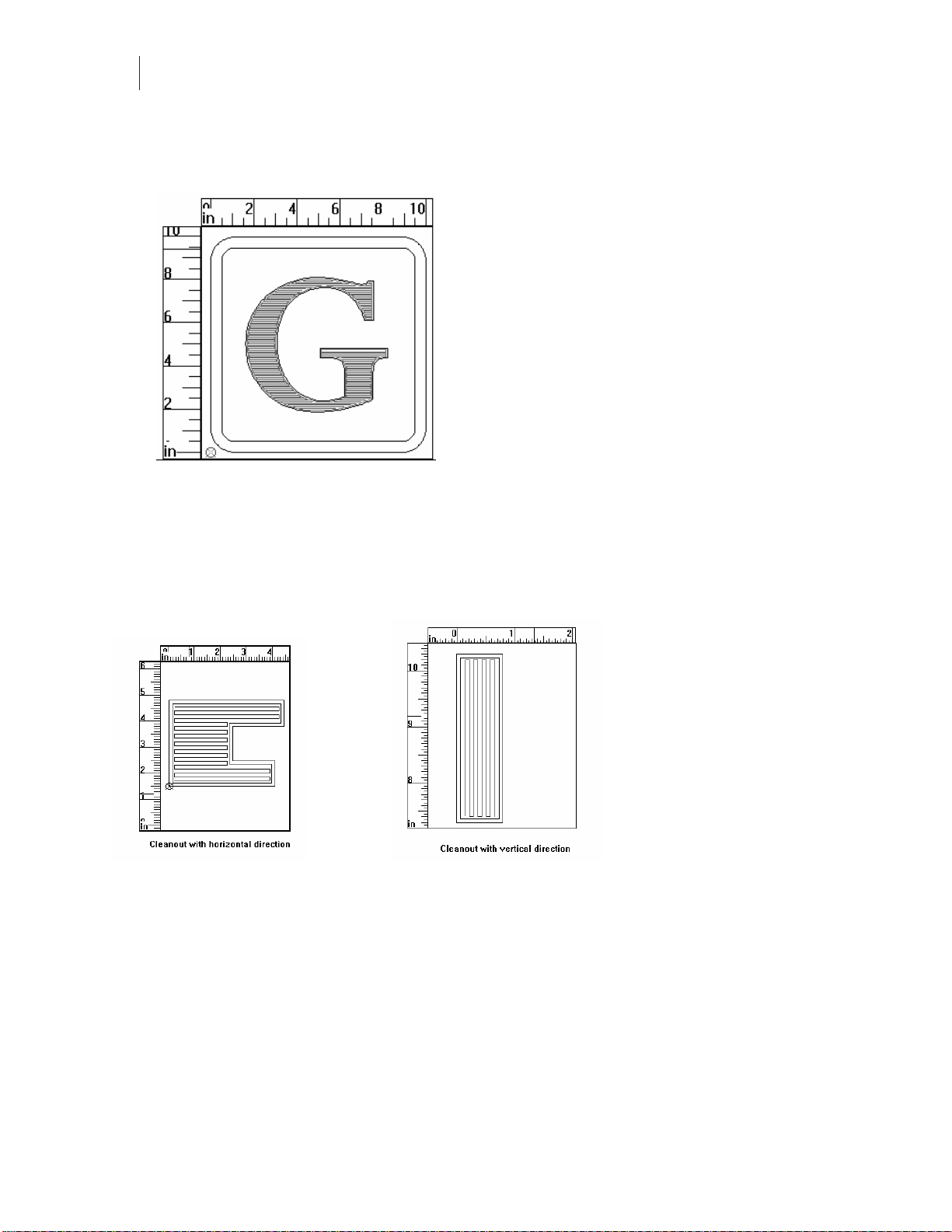
Direction
Cleanout Direction refers to the horizontal or vertical direction of the Cleanout tool path.
Selecting a Direction in Cleanout makes cutting cleanout shapes more efficient.
Use Horizontal when the design contains many horizontal elements. Use Vertical when the
design contains many vertical elements.
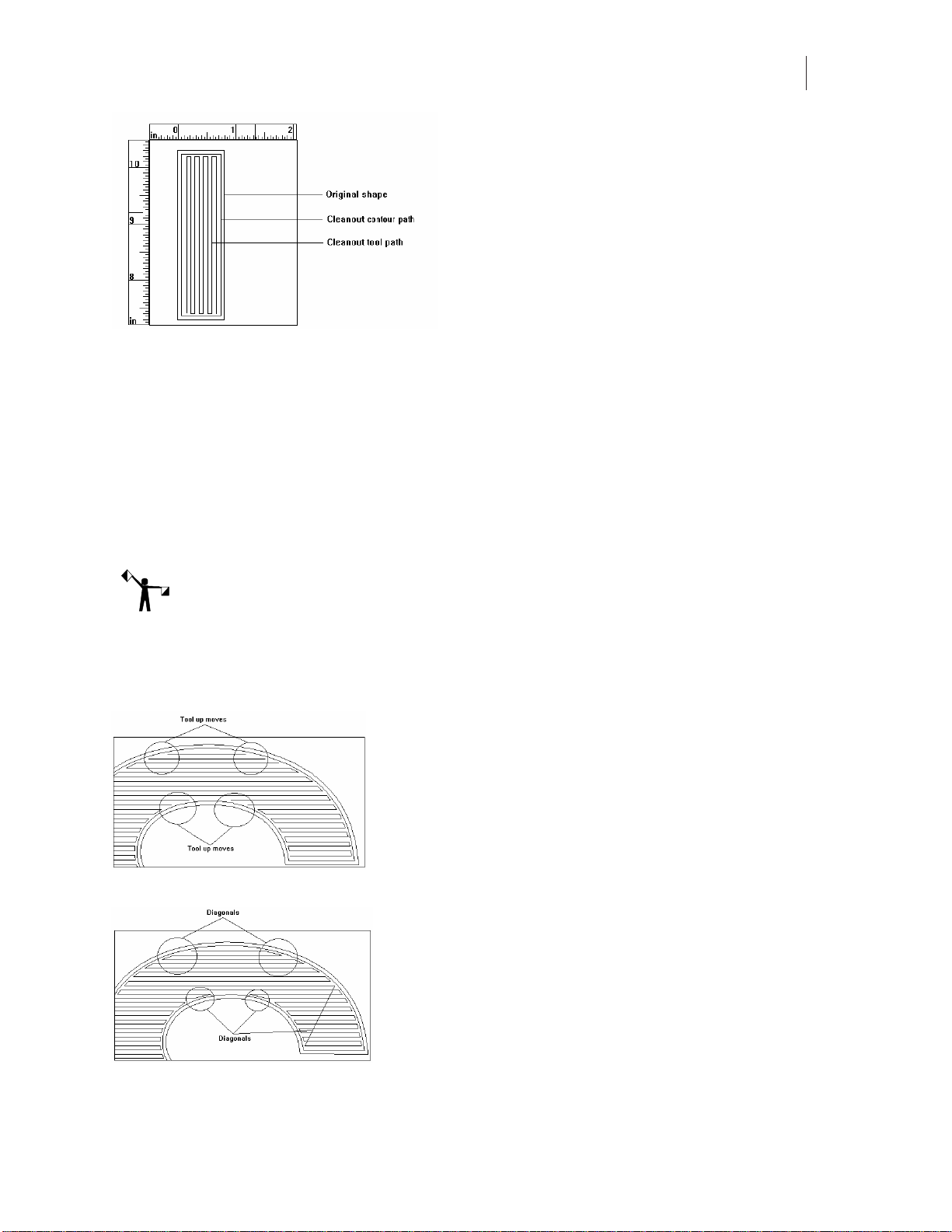
Cleanout tool path consists of two paths. The first is the cleanout path; the second path follows
the shape contour and smoothes the edge.
Page 27
19
Auto-Inlay Parameters
An inlay consists of a solid male shape that fits snugly into a stencil female shape or cleaned-out
area. A cleanout shape can be cut as an inlay shape. By applying Auto-Inlay to a Cleanout tool
path, the Cleanout shape is automatically cut with rounded corners. Auto-Inlay produces
shapes with matching corner radii, which do not require hand filing to ensure a good fit.
A typical use of Cleanout and Auto-Inlay is to clean out a foreground shape, and cut a mating
male shape for inlay.
To apply inlay to a Cleanout shape, click on the Auto-Inlay check box in the Cleanout dialog
box.
Note: A Cleanout Inlay shape and its mating shape must be cut with the same diameter tool.
Use Diagonals
The Use Diagonals feature allows certain shapes to be cut more efficiently by eliminating some
tool up moves by the router.
Shape with cleanout tool path without diagonals
Shape with cleanout tool path with diagonals
Page 28

Chapter 2
20
Reviewing t h e ART Path Toolbox
Drill
The Drill Tool allows the user to generate tool drilling positions designated on the design in
Composer. When the design is opened in the ART Path program, the drill symbol designates
the tool drilling position. Clicking on the Drill Tool opens the Default Drill Info Dialog Box.
Refer to the section “Toolpath Dialog Boxes” for more information. The shape must be selected
before the Drill Tool is available for use. The user must open a drill symbol from the Composer
Library before designating a drill tool path in the ART Path program.
If the drill symbol is larger than the tool chosen for the Drill tool path, no tool path is generated.
If the drill symbol is smaller than or equal to the tool, then the Drill tool path is generated.
To open and position a drill symbol from Composer
1 Create a design to be routed in Composer.
2 Click File. A drop down menu appears on screen.
3 Click Library. The File Open Dialog Box appears on screen.
4 From the Libraries List Box, click on Drill. The Drill.GCA’s appear in the Files List Box.
5 Click the desired drill symbol. Make sure the drill symbol chosen is not larger than the
routing tool.
6 Click Open. The chosen drill symbol appears in the working area.
7 Select the drill symbol with the Pointer Tool.
8 Use the Move Tool to position the drill symbol to the desired location in the design.
Repeat this process to add and position additional drill symbols to the design.
9 Save the design. The drill symbols appear on the design when the file is opened in the
ART Path program.
To set drill parameters to a f ile c ont ai ning drill symbols
1 Open a file containing drill symbols.
2 Select the drill symbol with the Pointer Tool. The selected shape changes in color to
show it is selected.
3 Click the Drill Tool from the Tool Box. The Default Drill Info Dialog Box appears on
screen.
4 Click the down arrow on the right side of the Tool entry box. A drop-down list box
appears.
5 Click the desired routing tool.
6 Enter the desired Drill parameter for the Total Depth, Depth Per Pass, Plunge Rate,
Surface Reference, Dwell Time, and Single Speed.
7 Click Generate to enter in the parameters. The tool path appears in a contrasting color.
Page 29

21
Nesting
Nesting allows the user to select, move, mirror, and rotate shapes for closer placement to
conserve material. When the Nesting Tool is clicked on in the toolbox, the mouse pointer
changes to a crosshair with a circle.
To move shapes using the nesting tool
1 Click left on the Nesting Tool. The Nesting Tool becomes available for use and the
mouse p ointer changes into a .
2 Set the cross hair on a shape (or draw a rubber band box around multiple shapes) and
click left on the mouse pointer to select the shapes.
3 Click right to "grab" the shape and move it to the desired location by moving the
mouse.
4 The keyboard can also be used to rotate, mirror, and position the shapes. All of the
Nesting methods may be used at the same time. Use the keys indicated to achieve the
moves desired.
♦ X - mirrors the shape in a horizontal direction
♦ Y - mirrors the shape in a vertical direction
♦ 1, 3, 5, or 9 - rotates the shape in a counterclockwise direction in 1, 30, 15, and 90
degree increments
♦ 2, 4, 6, or 0 - rotates the shape in a clockwise direction in 1, 30, 15, and 90 degree
increments
♦ The up and down arrow keys help position the shapes more closely together.
5 Click right to anchor the shapes in position.
6 Click the Nesting Tool to exit Nesting.
Page 30
Chapter 2
22
Reviewing t h e ART Path Toolbox
Horizontal Cutli ne
Horizontal Cutline inserts a horizontal cutline at a specified position into a design.
ART Path automatically inserts horizontal cutlines into a design that exceeds the height limits of
the router table. A cutline can also be placed in the design by the user to divide the design for
routing. A cutline may also be moved or removed to best suit the design needs using the Move
Cutline Tool.
Moving a horizontal cutline cannot result in creating a panel larger than the router will allow.
Any cutline the system requires for routing panels cannot be removed. It is recommended to
generate a tool path before inserting horizontal cutlines into a design. If the horizontal cutlines
are inserted before a tool path is generated the cutlines are deleted from the design and need to
be reinserted.
To create a horizontal cutline
1 Click Panels > Horizontal Cutline. The mouse pointer changes to a hand with a solid
red horizontal line across it that moves as the hand moves.
2 Move the horizontal cutline to the desired position.
3 Click the left mouse button to secure it.
4 Repeat steps 1 through 3 to insert another cutline. The cutlines are numbered in
sequence.
Move Cutline
Move Cutline allows the user to move a horizontal cutline to a different position in a design. A
Horizontal Cutline may be moved or removed to best suit the design needs using the Move
Cutline feature. Cutlines can also be dragged out of the rulers or created and moved using the
tools in the toolbox.
To move a horizontal cutline
1 Click Panels > Move Cutline. The mouse pointer changes to a hand.
2 Move the tool to the cutline to be moved.
3 Click and drag the cutline to the desired position.
4 Releasethemousebutton.
To remove a horizontal cutline
1 Click Panels > Move Cutline. The mouse pointer changes to a hand.
2 Movethetooltothecutlinetoberemoved.
3 Click and drag the cutline off the screen or until it meets another cutline.
4 Releasethemousebutton.
Page 31

23
To remove more than one horizontal cutline
1 Pull down the Panels menu and click on Move Cutline. The mouse pointer changes to
ahand.
2 Move the tool to a cutline.
3 Click and drag the cutline into the next one to be removed. The two horizontal cutlines
merge to create one cutline.
4 Repeat Steps 1 and 2 until all the desired cutlines are merged into one.
5 Click and drag the cutline off the working area. The cutline disappears.
6 Releasethemousebutton.
Auto-Carve 3D
The Auto-Carve 3D Tool lets you generate a three-dimensional tool path. For more information,
refer to the section “Auto-Carve 3D”.
Prismatic
The Prismatic Tool lets you generate a three-dimensional prismatic tool path. For more
information refer to the section “Prismatic”.
Set Start Point
The Set Start Point tool allows you to change the location at which the cutter begins routing.
To set a new start point
1 Create tool paths on the shapes to be routed.
2 Select the tool path with the Selection tool.
3 Click the Set Start Point tool and the cursor turns into an arrow. The default start point
is shown as a small square on the tool path.
Page 32

Chapter 2
24
Reviewing t h e ART Path Toolbox
4 Click and drag the Set Start Point arrow across the tool path at the location to set the
new start point. The new start point is designated by a small square and the original
start point is removed.
Page 33

25
Book Two:
Menus and Procedures
The ART Path programs are grouped by menu and procedures. The chapters in this book a
separated by menus and procedures within those menus.
♦ Chapter 3: File Menu
♦ Chapter 4: Edit Menu
♦ Chapter 5: Shape Menu
♦ Chapter 6: Setup Menu
♦ Chapter 7: ToolPaths Menu
♦ Chapter 8: Output Menu
♦ Chapter 9: Panels Menu
♦ Chapter 10: View Menu
♦ Chapter 11: Window Menu
♦ Chapter 12: Help Menu
Page 34

Page 35

27
Chapter 3:
File Menu
The Open command in the File Menu opens many different kinds of files including plot files
(PLT), job files (JOB), AutoCAD (DXF) files, router files (RTP), and many other files created by
popular graphics programs including Adobe Illustrator (AI) and Adobe Acrobat (PDF) files.
There are a variety of import filters that can be used when import the files. See OMEGA Help
for detailed explanation of each filter and its capabilities.
New
Choosing New in the File menu opens a new file or clean workspace in ART Path. To open a
new file in ART Path, choose New from the F ile menu. A new working area displays.
Open
Open loads a design saved as a plot, job, or router file into the working area. Open can also
open many other types of files listed in the Files of type drop-down list box.
Open is a command in the File menu. Open accesses the Open dialog box. The system defaults
to the Open dialog box each time the ART Path program is opened.
To open a file
1 Click File > Open. The Open dialog box appears.
2 In the Look In list box, click the down arrow to list the available drives. Click the
desired drive letter and folder.
3 In the Files of Type list box, click the down arrow to list the file types. Click the desired
file type.
4 To choose the file, click the name of the file in the File name list box. If needed, click on
the scroll arrows to show file names that are not currently visible in the list. The file
name is highlighted.
5 Click OK. The design will appear in the working area.
Close
Clicking Close in the File menu closes the open file but does not close the ART Path program.
Page 36

Chapter 3
28
File Menu
Save
Choosing Save in the File menu keeps all changes made to a design. The design is saved as a
router (RTP) file using the previously assigned name and directory.
A file is updated each time you save. If the design already has a file name, then the previous
version of the design is replaced.
Designs are automatically saved to the hard disk as a router file into the C:\Jobs directory. The
system adds an RTP extension to the end of the file name. If the file was opened from the floppy
or CD drive the file will be saved to that drive and not the hard drive.
The Save command is available only when a design has been opened and has changed in
appearance. Job and plot files are automatically saved as router files. A copy of the job or plot
file remains in its original form.
To save new changes to an already named file
1 Click File > Save.
2 The system automatically saves the changes in the design without leaving the working
area. The file will be saved as a router file with an .RTP file extension.
Save As
Choosing Save As in the File menu accesses the Save As dialog box. Here, you can keep all
changes made to a design and store the design as a router file using the same file name or a
different file name.
When Save As is clicked, the edited version of a file may be saved under a unique name. The
original file does not change and is not replaced. The file extension for router files (RTP) is
added at the end of the file name. If the same file name is given to two different designs, a
message box appears asking if the previously stored design is to be replaced by the new design
havingthesamename.SaveAscanalsobeusedtosaveafilewiththesamename.
Save As also allows the design to be saved in a different drive or directory. When no drive is
designated, the file is automatically saved to the hard disk as a router file into the C:\Jobs
directory.Adesignmayalsobesavedasarouterfileontoadiskette.SaveAsisusefulfor
changing an existing design and keeping an original version without any changes.
The system automatically adds an RTP extension to the file name. When using the Save As
command, job and plot files are automatically saved as router files. A copy of the job or plot file
remains in its original form.
Router files can be opened/imported into Composer or GSPPlot. If extensive editing of a router
file is necessary, the original plot or job file should be opened and edited in the Composer
program.
To save changes to a file and keep the original version
1 Click File > Save As. The Save As dialog box appears on screen.
2 Type in a file name in the File name text box.
3 Click OK to save the new file name. The new file name appears in the title bar.
Page 37

29
Save Plot File
Save Plot File in the File menu keeps all changes made to a design and stores the design as a
plot file using the same file name or a different file name.
When Save Plot File is clicked, the edited version of a file may be saved under a unique name.
The original job or router file does not change and is not replaced. The file extension for plot
files (PLT) is added at the end of the file name.
Save Plot File is useful for changing an existing design but keeping the original version of the
file unchanged. If the same file name is given to two different designs, a message box appears
asking if the previously stored design is to be replaced by the new design having the same
name.
Save Plot File also allows the design to be saved into a different drive or directory. When no
drive is designated, designs are automatically saved to the hard disk as a plot file into the
C:\Jobs directory. A design may also be saved as a plot file onto a diskette.
When using the Save Plot File command the original version of the plot file is overwritten with
the new plot file information.
The system automatically adds a .PLT extension to the file name. When using the Save Plot File
command, job and router files are automatically saved as plot files. A copy of the job or router
file remains in the system in its original form.
To save the file as a plot (PLT) file
1 Click File > Save Plot File to open the Save As dialog box. The file type to save as is
PLT.
2 Choose a folder to Save in. The default folder for plot files is C:\Jobs.
3 Type in a file name in the File name text box.
4 Click OK to save the file as a PLT file.
Save to Spool File
Organize your workflow when processing large files by saving to spool (SPL) files. An SPL file
allows you to rout the job at your convenience, without having to render the job at that time.
Creating an SPL file is particularly beneficial when working with large files.
You can create a SPL file and send it to the router at the same time by turning on the Send file to
router check box in the Save as dialog box. After creating the SPL file open it in GQ Manager
and send it directly to the router using the File > Open & Cut command.
To save a spool file
1 Click File > Open to open an existing file.
2 Click File > Save to Spool File to open the Save As dialog box.
3 Turn on Send file to router if you wish to output the job to the router while you save
the spool (SPL) file.
Page 38

Chapter 3
30
File Menu
4 Choose the folder to Save in.
5 Type the file name.
6 Click Save.
Note: You cannot edit an SPL file. If you change the original RTP file you must save it again as
an SPL file to reflect the changes.
Save Parameters
A parameter (PRM) file containing all of the job settings is created when a job is output. If you
set up a job with tool paths, repeats, or other job output settings and then choose not to rout the
job, you can save these parameters in a PRM file. When you later reopen the RTP file, the saved
PRM file resets the job parameters.
To save job paramets
1 Setup a job with tool paths, repeats, etc.
2 Save the file as an RTP file using File > Save As.
3 Click File > Save Parameters to save the settings in a PRM file.
Place
Choosing Place in the File menu merges the contents of a saved file with the currently displayed
design. The Place command is available only after a file has been opened. Place accesses the File
> Open dialog box. Place can be used repeatedly to merge additional files into the currently
displayed design. Previously selected shapes become deselected as the saved file appears on the
screen.
To place a design into an opened fil e
1 Click File > Open. The Open Dialog Box appears.
2 Choose the file you wish to have as the current design and click OK.
Page 39

31
3 Click File > Place. The Open dialog box appears.
4 Choose the file you wish to merge with the current design, then click OK. The merged
file appears selected in the center of the working area.
5 Use the Place command repeatedly to merge additional files into the current design.
Library
Clicking on Library in the File menu opens the Open dialog box so that you can choose a Gerber
library file (GCA) to add to a job. For example, if you design a job in Composer and later decide
that you need drill holes to mount the sign, you can go to the library, open a drill file, and add
holes to your design. Use the Nesting tool to move the drill holes to the proper location. This
feature saves you from having to go back to Composer to make design changes, then
reapplying tool paths to the changed design.
Print
Clicking Print in the File menu opens the Windows standard Print dialog box. Please refer to
your Microsoft Windows documentation for using this dialog box.
Print Setup
Clicking Print Setup in the File menu opens the Windows standard Print Setup dialog box.
Please refer to your Microsoft Windows documentation for using this dialog box.
Recently Used File list
The Recently Used File list in the File menu displays the last eight files that were accessed in
ART Path.
Exit
Clicking Exit in the File menu closes the ART Path program.
Page 40

Page 41

33
Chapter 4:
Edit Menu
Edit commands allow the user to change the condition of job, router, or plot files in the working
area. The following commands are available for editing purposes.
Undo
Choosing Undo from the menu bar cancels the previous editing operation. Undo must be
clicked on immediately after making an error. Undo will undo only the previous command. To
cancel the previous editing operation, choose Undo from the Edit menu before clicking
anywhere in the working area. The last edit is cancelled.
Cut
Choosing Cut from the Edit menu removes a selected shape from the working area and puts it
on the clipboard. A cut shape can be placed back into a working area using the Paste or Paste
Back command as many times as desired. Cutting is similar to cutting out a picture with a pair
of scissors.
Cut is available only when a shape is selected in the working area. The clipboard holds one Cut
at a time. When another Cut is made, any previously cut shape already on the clipboard is
deleted and replaced by the newly Cut shape.
To cut a shape for storage on the clipboard
1 Select the shape in the design. The shape is redrawn in a different color.
2 Click Edit > Cut. The selected shape is removed from the working area and sent to the
clipboard.
3 UsethePasteorPasteBackcommandtoaddthecutshapeintoanotherdesignor
place the design in its original position in the working area.
Copy and Paste
Choosing Copy from the Edit menu places a copy of a selected shape in the working area on the
clipboard. The original selected shape remains in the working area. A copied shape can be
placed back into a working area from the clipboard using the Paste command as many times as
desired.
Copy is available only when a shape is selected in the working area. The clipboard holds one
Copy at a time. When another Copy is made, any previously copied shape already on the
clipboard is deleted and replaced by the newly copied shape.
Page 42

Chapter 4
34
Edit Menu
To copy a shape from a design
1 Select the shape in the design. The shape is redrawn in a different color.
2 Click Edit > Copy. The original selected shape remains in the working area as a copy
of it is sent to the clipboard.
3 Use the Paste command to add the copied shape at the exact location it was copied
from in the design.
To create multiple copies of a shape
1 Select a shape in the design. The shape is redrawn in a different color.
2 ClickEdit>CutorCopy.
3 Click Edit > Paste. The selected shape appears in the working area.
4 The shape must be moved to the desired location using the Nesting Tool.
5 Repeat steps 3 and 4 to create as many copies as required.
To move a shape from one file to another
1 Select a shape in the design. The shape is redrawn in a different color.
2 Click Edit > Copy or Cut.
3 Click File > Open.
4 Open the desired file that will receive the new shape from the clipboard.
5 Click Edit > Paste. The selected shape appears at the exact location it was cut or copied
from the design.
6 The shape must be moved to the desired location us ing the Nesting tool.
Paste from Composer
Paste lets you insert objects from Composer directly into ART Path. Choosing Paste inserts the
contents from the Composer clipboard into the ART Path working area. You can paste the
Composer contents into the working area as many times as desired. Use the Nesting tool to
move the added shape to the proper location.
♦ Paste places a shape in the middle of the work area.
♦ Paste Back replaces the shape in its original location in the job.
♦ Paste Back does not place the copied shape in its original position if placed in a
different file
Note: You cannot paste objects from any application other than Composer, it is possible to
cut/copy an object in ART Path and Paste it into Composer.
Page 43

35
To paste a Composer object int o ART Pat h
1 In Composer, open the file that contains the object you want to paste into ART Path.
2 Select the object and choose Cut or Copy from the Composer Edit menu to place the
object onto the Composer clipboard.
3 In ART Path, open the desired plot, job or router file that will receive the pasted object.
4 Click Edit > Paste. The object stored in the clipboard is placed in the working area. The
pasted object is selected and all previously selected shapes in the current design are
deselected.
5 The object can be moved to the desired location in the working area using the Nesting
tool.
6 To paste in multiple copies of the object, repeat steps 4 and 5.
Paste Back
Paste Back inserts the contents from the clipboard into the ART Path working area. If you
copied the object in ART Path, Paste Back inserts the object back in the same location in the
same design.
Delete
Choosing Delete from the Edit menu permanently removes a selected shape from the working
area. The Undo command restores any shape or design deleted by mistake if it was the last
command accessed. To delete a shape, select the desired shape to be deleted and choose Delete
from the Edit menu. The shape is removed from the working area.
Select All
Choosing Select All in the Edit menu selects all shapes in a design. The design is selected and
redrawn in a different color.
Reverse Select
Choosing Reverse Select in the Edit menu changes the selection condition of a shape. Any
selected shapes become deselected. Any shapes not selected become selected.
To reverse select shapes
Click Edit > Reverse Select. The deselected shapes become selected, and the selected shapes
become deselected.
Select Open Shapes
Select Open Shapes determines if any shapes in the design are open. If Select Open Shapes is
gray, the design contains no open shapes. If SelectOpen Shapes is black, the design contains
open shapes.
Page 44

Chapter 4
36
Edit Menu
To select open shapes
1 Click Edit.
2 If Select Open Shapes is black, click on it to determine which shapes are open.
Note: All open shapes will be selected. It may be appropriate for some shapes to remain open,
such as shapes for engraving.
3 To close shapes, use the Join command in the Shape menu.
Select Unused Shapes
Clicking the Select Unused Shapes command selects (highlights) design shapes which do not
have a tool path assigned. This is useful for checking the design before routing to make sure
that all shapes have an assigned tool path. It can also be used to select and delete shapes which
you do not want to route (for example, when using clip art, you may not want all of the design).
Page 45

37
Chapter 5:
Shape Menu
The Shape menu provides commands that allow you to repeat, size and close shapes.
Repeats
Repeats creates multiple copies of a shape alongside and above the original in the working area.
Clicking on Repeats opens the Repeats Dialog Box. The spacing between repeated shapes may
be changed two ways using: Gap and Distance.
A shape must be selected to be repeated. The amount of times a shape can be repeated in a
horizontal direction (x-axis) is limited to the width of the material. The amount of vertical
repeats (y-axis) is not limited. If the repeated shapes exceed the material length, the pull-down
method can be used to add material as needed.
Repeats dialog box
Repeats creates multiple copies of a shape alongside and above the original in the working area.
A shape must be selected before it may be repeated.
Gap
Gap is the space between repeated shapes. Negative Gaps are ok.
♦ X Gap: X Gap is the distance between repeated shapes in the x-axis. It defaults to 0.100
inches.
♦ YGap: Y Gap is the distance between repeated shapes in the y-axis. It defaults to 0.100
inches.
Distance
Distance sets the space between the centers of the repeated shapes. Distance must be greater
than or equal to 0.
Page 46

Chapter 5
38
Shape Menu
♦ X Distance: X Distance is the center to center distance of repeated shapes in the x-axis.
♦ Y Distance: Y Distance is the center to center distance of repeated shapes in the y-axis.
Repeats
♦ Number of X Repeats: X Repeats are the number of copies of the original shape
created to the right of the original. X Repeats defaults to 1.
♦ Number of Y Repeats: Y Repeats are the number of copies of the original shape
created above the original. Y Repeats defaults to 1.
Tip: Preferences command button saves the current Repeat settings. These s ettings will be
applied ea c h time a shape is repeated in AR T Path. Th e Preference sett in g s remain in effect
until the Preference comman d bu t to n is click ed o n agai n.
To adjust the space between the selection boxes sur r oundi ng r epeated shapes
1 From inside the Repeats Dialog Box, click the Gap option button to turn it on.
2 To create multiple copies to the right of the original (x-axis), enter a value in the
Number of X Repeats text box.
3 To create a gap in the X axis, enter a value in the X Gap text box.
4 To create multiple copies above the original (y-axis), repeat the previous steps,
changing the value for Number of Y Repeats and Y Gap.
5 Click Repeat to save the number of Repeats and the Gap space. The multiple copies are
created.
To set the distance between the centers of rep eat ed shapes
1 From inside the Repeats Dialog Box, click the Distance option button to turn it on.
2 To create multiple copies to the right of the original (x-axis), enter a value in the
Number of X Repeats text box.
3 To create repeats with spacing from the center of the shapes, enter a value in the X
Distance text box.
4 To create multiple copies above the original (y-axis), repeat the previous steps,
changing the value for the Number of Y Repeats and Y Distance.
5 Click Repeat to save the number of Repeats and the Distance. The multiple copies are
created at the specified distance apart.
Sizing Shapes
There are two ways to change the size of a shape – by a specific percentage or to a specific size.
A shape must be selected to be s ized. Shapes on which a toolpath has been generated cannot be
resized. You must delete the toolpath before resizing the shape.
Page 47

39
Percent Size dialog box
Percent Size changes the size of a shape by a specific percentage.
Size Type
♦ Uniform changes the overall size of a shape by a desired percentage. It is an option
button in the Percent Size dialog box. The system defaults to Uniform and shows the
size of the selected shape is 100.0 %, meaning that the shape is full size. Changing the
Uniform Size adjusts the height and length of the shape equally. A shape must be
selected to be sized.
♦ Non-uniform changes the length and height of a shape by separate percentages. It is
an option button in the Percent Size dialog box. The system defaults to Uniform and
shows the overall size of the selected shape is 100.0. Selecting Non-uniform creates a
Length text box and a Height text box for typing in changes to the shape.
♦ Length: Changes the length of the shape by a percentage.
♦ Height: Changes the height of the shape by a percentage.
Size From
♦ Size From LowerLeft Corner: The shape changes size with the lower left point
remaining in the same position.
♦ Size From Center: The shape changes size from the center handle.
To change the overall size of a shape by a specific percentage
1 Select the shape to be resized.
2 In the Percent Size dialog box, double-click the mouse pointer in the Size text box to
highlight it.
3 Type in a percent value. Typing in a value greater than 100 increases the shape’s size.
Typing in a value less than 100 decreases the shape’s size.
4 Click the Left Corner option button to size the shape from the left corner, or click on
the Center option button to size the shape from the center.
5 Click the Size command button to save the new value and return to the working area.
Page 48

Chapter 5
40
Shape Menu
To change the length and height of a shape by s epar at e per centages
1 Select the shape to be resized.
2 In the Percent Size dialog box, click the mouse pointer on the Non-uniform option
button to select it. Separate text boxes for the Length and Height appear.
3 Double-click the mouse pointer on the Length or Height text box. The box becomes
highlighted.
4 Type in a percent value. Typing in a value greater than 100 increases the shape’s size.
Typing in a value less than 100 decreases the shape’s size.
5 Double-click the mouse pointer in the remaining Size text box and type in a value.
6 Click the Left Corner option button to size the shape from the left corner, or click on
the Center option button to size the shape from the center.
7 Click the Size command button to save the new values and return to the working area.
Absolute Size dialog box
Absolute Size changes the overall length and height of a shape to a specific size. A shape must
be selected to be sized. Shapes on which a toolpath has been generated cannot be resized. You
must delete the toolpath before resizing the shape.
Size Type
♦ Uniform changes the length and height of a shape proportionally. Any increase or
decrease in the Length will automatically increase or decrease the Height. This is also
true of adjusting the Height. The system defaults to Uniform. The bottom of the dialog
box displays the area of the selected shape and the height and length are shown as
percentages.
♦ Non-uniform changes the length and height of a shape individually by specific values.
Clicking Non-uniform allows you to type in separate values for length and height. The
bottom of the dialog box displays the area of the selected shape and the height and
length are shown as percentages.
♦ Length: Shows the length of the shape.
♦ Height: Shows the height of the shape.
Page 49

41
Size From
♦ Size from Lower Left Corner: The shape changes size from the lower left handle only.
The point remains in the same position.
♦ Size from Center: The shape changes size from the center handle.
To change the length or height of a shape individually to specific sizes
1 In the Absolute Size dialog box, click on the Non-Uniform option button. A solid dot
fills the button meaning the function is on.
2 Double-click the mouse pointer in the Length text box to highlight it and type in a
desired value.
3 Double-click the mouse pointer in the Height text box to highlight it and type in a
desired value.
4 Click the Left Corner option button to size the shape from the left corner, or click on
the Center option button to size the shape from the center.
5 Click Size to save the new value and return to the working area. The shape is redrawn
showingthe changes.
To change the length and height of a shape proportionally to a specific size
1 Click the Uniform Option button.
2 In the Absolute Size dialog box, double-click the mouse pointer in the Length or
Height text box to highlight it.
3 Type in a desired value.
4 Click the Left Corner to size the shape from the left corner, or click Center to size the
shape from the center.
5 Click Size to save the new value and return to the working area. A proportional
increase or decrease is applied to the other size text box.
Join
Join closes open shapes. The Join command closes open shapes by automatically connecting the
open points. For open points to be joined automatically, they must be within a distance from
each other that is specified by the Join Tolerance command, described in the Setup menu.
To join open shapes
1 Click Edit > Open Shapes. Any open shapes are highlighted.
2 Click Shape > Join. All open shapes that fall within the Join Tolerance should be
joined.
3 Click Edit > Select Open Shapes to verify that open shapes have been joined. If the
open points do not fall within the default Join Tolerance, they will not be joined. If
necessary, adjust the tolerance by using the Join Tolerance command.
Page 50

Chapter 5
42
Shape Menu
Group
Group combines shapes so that you can work with them as a single object. You can select, copy,
mirror, rotate, and size grouped shapes as a unit. Grouping shapes together makes it easy to
move them on the work area. You may select the grouped shapes and apply one tool path to the
entire group.
When selecting grouped shapes, all components of the group display in a contrasting color.
To group shapes
1 Choose the shapes to group with the Pointer tool or the Select All command.
2 Click Shape > Group (F6).
Ungroup
The Ungroup command separates previously grouped items into individual shapes. Ungroup is
only available if the design has grouped shapes.
To ungroup shapes
1 Choose the shapes to ungroup with the Pointer tool or the Select All command.
2 Click Shape > Ungroup (F5).
Layer
Some file formats imported into ART Path (PLT or DXF, for example) have layers that contain
common features such as engraving or drilling. You see which shapes are on the layers of the
design by choosing the layer command in the Shape menu. All components of the chosen layer
displayin a contrasting color.
Tip: Ev ery j o b has at l east one lay er w h i c h is named the same name as the file
To view layers by menu selection
1 Open a file with layer data.
2 Click Shape > Layer and choose a layer from the drop down list. The portion of the
design assigned to that layer displays in a contrasting color.
To view layers by selecting the design
1 Open a file with layer data.
2 Using the pointer tool select a portion of the design. All parts of the design assigned to
that layer display in a contrasting color.
3 Click Shape > Layer. A checkmark appears next to the layer associated with the
highlighted part of the design.
Page 51

43
SmartEdit Layer
After generating tool paths for a layer of a design you can modify the tool path with the
SmartEdit Layer command. Choose a layer to edit from the SmartEdit Layer list and ART Path
returns to the tool path’s Current Info dialog box.
You cannot SmartEdit a layer if tool paths have not been generated for the layer. If you attempt
to SmartEdit a layer without a generated tool path, the tool path Info dialog box does not
display.
To SmartEdit a layer
1 Click Shape > SmartEdit Layer and choose a layer from the drop down list. The
current tool path Info dialog box opens.
2 Make any changes to the parameters.
3 Click Generate.
Page 52

Page 53

45
Chapter 6:
Setup Menu
Setup Commands allow you to choose the router, set the material size, and change the starting
and ending positions of the job. In Tool Edit, you can add, delete, or change tools. Setup
Commands also let you set the nesting display and the tolerance range of Join Tolerance.
Tool Edit
Choosing Tool Edit from the Setup menu accesses the Tool Information Dialog Box.
Tool Information Dialog Box
The Tool Information Dialog Box is used to add, remove or change routing tool information.
♦ Available Tools is a list of the routing tools available for routing a design. This list
includes the standard straight and v-cutter tools available from Gerber. Available
Tools shows the size, tool changer position, and description of each tool.
The tool changer position column uses the format /00 - /10, where /01 indicates a tool
assigned to the first position of the tool changer, /02 a tool assigned to the second
position, and so on. /00 indicates that the tool has not been assigned a position in the
tool changer.
♦ Add command button opens the Tool Edit dialog box so that you can add a router tool
to the Available Tools list box.
♦ Delete command button removes a router tool from the Available Tools list box.
♦ Change command button opens the Tool Edit dialog box so that you can change the
size, type, angle, description or tool changer position of an existing tool in the
Available Tools list box.
Page 54

Chapter 6
46
Setup Menu
Tool Edit Dialog Box
The Tool Edit Dialog Box appears on screen when a tool is added or changed in the Tool
Information dialog box. It sets the size and description of a router tool added or changed in the
Available Tools list box.
♦ Tool Type enables you to specify whether the router is a straight or v-cutter tool.
♦ Tool Diameter is the diameter of the router tool. Tool diameters range from 1/16 inch
to 2 inches. All tool diameters must be entered in decimal form. For example a ¼ inch
tool bit diameter is entered in as .25. If more than one tool is entered in the tool list
with the same diameter but with a different description, the tools are treated as
separate entries.
♦ Tool Angle is used to specify the angle of v-cutter tools.
♦ Tool Changer Position, if your system has one, it will enable you to assign a tool to a
position in the tool changer.
♦ Tool Description allows you to type in a description of the router tool.
♦ The Continue command button saves the information entered in the Tool Edit Dialog
Box and returns to the Tool Information Dialog Box.
♦ The Cancel command button aborts the Tool Edit Dialog Box and returns to the Tool
Information Dialog Box.
To add a routing tool
1 Click Setup > Tool Edit. The Tool Information Dialog Box appears on screen.
2 Click Add. The Tool Edit Dialog Box appears on screen.
3 Select either Straight or V-Cutter in the Tool Type box.
4 Type in the size of the tool to be added in the Tool Diameter entry box. Tool sizes must
be entered in decimal form. For example 1/4 inch tool would be entered in as .25.
5 If the selected tool type is a V-Cutter, then type in angle of the tool in the Tool Angle
entry box.
6 If you have a tool changer and want to assign the tool to a position, enter a number
from 1 - 10 in the Tool Changer Position entry box.
7 Type in the description of the tool to be added in the Tool Description entry box.
8 Click Continue to return to the Tool Information Dialog Box.
Page 55

47
To remove a routing tool
1 Click Setup > Tool Edit. The Tool Information Dialog Box appears on screen.
2 Click the routing tool to be removed from the Available Tools list. The tool is
highlighted.
3 Click Delete. The tool is removed from the list.
To change an existing routing tool
1 Click Setup > Tool Edit to open the Tool Information dialog box.
2 Click the desired routing tool. The tool is highlighted.
3 Click Change. The Tool Edit Dialog Box appears on screen.
4 Make the necessary changes in the Tool Edit dialog box.
5 Click Continue to return to the Tool Information dialog box.
Assigning Tool Positions in the Tool Changer
The automatic tool changer is a separately purchased Sabre option. You can load as many as ten
tools in the changer’s carousel. After you send the job, the tool changer loads the first tool in the
job into the spindle and s tarts routing. When another tool is needed, the spindle stops, the tool
changer removes the old tool, loads the new tool, and starts routing again.
Tools are assigned to a carousel position in ART Path. Installation, use, and maintenance of the
automatic tool changer are contained in the manuals p rovided with the tool changer option.
You do not need to assign tools in the order they are used in the job. Also, if you assign tools
that are not used in a job, only the necessary tools are used and the changer skips unused tools.
For example, the carousel may start with tool position 5, change to position 1, and then change
to position 7 if those are the three tools used in a particular job.
To assign tool positions usi ng the Tool Edit dialog box
1 Click Setup > Edit. The Tool Information Dialog Box opens.
2 Click the desired routing tool and click on Change. The Tool Edit Dialog Box opens.
3 Enter a number from 1 - 10 in the Tool Changer Position entry box. Enter a zero (0) to
remove the tool from an assigned position in the tool changer.
4 Click Continue to return to the Tool Information Dialog Box.
Page 56

Chapter 6
48
Setup Menu
To assign tool positions usi ng t he J ob O ut put dialog box
1 Click Output. The Job Output dialog box appears on the screen.
2 Click the Use Automatic Tool Changer check box.
3 Click the Rout button. The Select Tool(s) Changer Position dialog box appears on the
screen. The top half of the dialog lists the tools that are not assigneda tool changer
position. The bottom half lists the tools assigned to tool changer positions 1 - 10.
4 To add an unassigned tool, highlight that tool in the Unassigned Tools list and click on
Add. The tool is assigned to the first "EMPTY" position in the Assigned Tools list.
5 To change tool position assignments, highlight an assigned tool and drag it to an
"EMPTY" position.
6 To remove a tool from an assigned tool changer position, highlight the assigned tool
and click Remove. That tool is now placed in the Unassigned Tools list.
7 If you want to pause the tool after it is picked up by the tool changer, highlight the tool
in the Assigned Tools list and click Pause On/Off. An X appears to the left of the tool
indicating that routing stops until you restart it at the control panel.
8 When you complete assigning tool positions, click Continue to send the job to the
router.
Start/End Position
Start/End Position sets the position where the tool will Start/End routing relative to the design.
Start/End Position is a command in the Setup menu. Selecting Start/End Position opens the
Start/End Position dialog box. There are eight Start and eight End Positions. A green X appears
in the working area at the position the tool will start routing from. A red circle appears in the
working area at the position where the tool will end routing. Start/End Position may be set as a
Preference setting. Start/End Position can also be accessed from the Job Output Dialog Box.
Page 57

49
To change where the routing tool will start
1 Click Setup > Start/End Position. The Start/End Position Dialog Box appears on the
screen.
2 Click a desired Start position.
3 Click OK to save the new position. The design is redrawn in the working area with an
X showing the Start position.
To change where the routing tool will end
1 Click Setup > Start/End Position. The Start/End Position Dialog Box appears on
screen.
2 Click a desired End position. A solid dot fills the option button meaning the position is
on.
3 Click OK to save the new position.
To view where the routing tool wil l star t and end
1 Click Setup > Start/End Position. The Start/End Position Dialog Box appears on
screen.
2 A green X appears on the work surface at the position the tool will start routing from
in the design. A red circle appears at the position where the tool will end routing or
click Output. The Start/End Position is also shown in the Job Output Dialog Box.
Page 58

Chapter 6
50
Setup Menu
Router Selection
Choose Router Selection in the Setup menu to open the Router Selection Dialog Box that allows
the user to select the router used when a design is routed. This command can only be used if
more than one router is connected to the OMEGA system and added to the list in GSP Setup.
The related dialog box allows the user to choose a router on which the design is to be routed.
The Router Selection automatically changes when a job is opened that is set up for a different
router in GSP Setup.
Router Selection Dial og Box
When more than one router is installed on a OMEGA system, the Router Selection Dialog Box
appears on screen when the ART Path program is opened. The dialog box allows you to choose
the router on which the design is to be routed. You can also choose a router at any time by
clicking on Router Selection in the Setup Menu.
Note: The Router Selection command is available only when more than one router is connected
to the system and added to the Plotter/Router list in GSP Setup.
OK command button enters in the selections from the Router Selection Dialog Box and returns
to the ART Path program.
To select a router at program st ar t up
1 Double-click the ART Path icon or click Start > All Programs > GSP OMEGA > ART
Path32 to open the program. The Router Selection Dialog Box automatically appears
on screen.
2 Click the router name that will be used to rout the current design.
3 Click OK to enter in the selection and exit the Router Selection Dialog Box. The screen
may redraw to adjust to the size of the selected router.
To select a router after a file is opened
1 Click Setup > Router Selection. The Router Selection Dialog Box appears on screen.
2 Click the Router Name that will be used to rout the current design.
3 Click OK to enter in the selection and exit the Router Selection Dialog Box. The screen
may redraw to adjust to the size of the selected router.
Use Material
The Use Material command in the Setup menu allows the user to view a rectangle that
represents the material to be cut for the job. Use Material is useful when sending multiple jobs
or shapes using the same material, to the router without losing registration.
To turn on use material
1 Click Setup > Use Material. A check mark appears next to the Use Material command
to show that it is turned on. A rectangle appears on screen along with the design to
represent the sheet of material on the router.
Page 59

51
2 Use the nesting tool to position the design within the rectangle.
To turn off use material
1 Click Setup > Use Material. The checkmark is removed from next to the Use Material
command. The screen redraws without the material rectangle.
Material Size
The Material Size command in the Setup menu allows the user to enter in the size of the
material to be cut for the job. The material appears on the screen as a rectangle, and aids in the
moving and nesting of shapes in the design. Selecting Material Size opens the Material Size
Dialog Box.
♦ The X Material Size text box allows the user to enter in a material length value.
♦ The Y Material Size text box allows the user to enter in a material height value.
♦ The Preference command button saves the current X and Y material size settings.
These settings are applied to all designs each time the Material Size Dialog Box is
accessed in the ART Path program. The Preference settings remain in effect until the
Preference command button is clicked on again and parameter changes are made.
♦ The OK command button enters in the selections from the Material Size Dialog Box
and returns to the ART Path program.
♦ The Cancel command button aborts the Material Size Dialog Box and returns to the
ART Path program.
To enter in the size of the material to be cut
1 Click Setup > Material Size. The Material Size Dialog Box appears on screen.
2 Enter the material length in the X text box.
3 Enter the material height in the Y text box.
4 Click OK to enter in the X and Y values and exit the Material Size Dialog Box. A
rectangle appears on screen representing the material. The user cannot select or move
the material rectangle.
Page 60

Chapter 6
52
Setup Menu
Nesting Setup
Nesting Setup is a command in the Setup menu that lets you display the outermost shape or
both the inner and outermost shapes of a nested shape. Selecting Nesting Setup opens the
Nesting Setup dialog box.
To set up nesting
1 To display the outermost shape, click Show Outermost Shapes when Dragging.
2 To display both outermost and innermost shapes,click Show Innermost/Outermost
Shapes when Dragging.
3 To save your selection as the default, click on Preference.
4 Click OK.
Join Tolerance
The Join Tolerance dialog box allows you to increase or decrease the distance allowed between
shape points that will be closed automatically by the Join command. If the shapes you want
closed by the Join command were not closed, increase the Join Tolerance.
To increase or decrease the join tolerance
1 Type a new tolerance in inches or millimeters in the Join Tolerance dialog box.
2 To save this tolerance as the default, click Preference.
3 Click OK.
4 Click Shape > Join. All open points within the distance tolerance that you just entered
are joined.
Page 61

53
Show Tool Changer Position
Click on this command to turn it on and display the tool changer positions in the Tools Used in
Job dialog box. For more information on Tools used, refer to the “Tool Path menu” section. The
Tool Changer positions will be displayed in each of the toolpath dialog boxes.
Page 62

Page 63

55
Chapter 7:
Tool Path Menu
The Tool Paths Menu allows the user to choose the type of tool path the router tool will follow
when routing a shape.
Tools Used
The Tool(s) Used in Job dialog box lists all the tools used in the current job. This list does not
display the order that the tools are used - that information is shown in the Organize Tool Order
dialog box.
Organize Tool Order dialog box
The Organize Tool Order dialog box allows you to view and change the order that tools are
used when routing.
In the Job Output dialog box, click on the Rearrange Output Tool Order check box and then
click on Rout to open the Organize Tool Order dialog box. This dialog lists the tools used in the
job, the order they are used, and depth of cut for each tool path.
The major benefit of this dialog box is to display the order in which the tools are used so that
you have the next tool ready to install for a manual tool change. The order that tools are used is
optimized by ART Path software to provide the most efficient and safe order. You should not
Page 64

Chapter 7
56
Tool Path Menu
change the order unless you are a very advanced user with a great depth of knowledge about
routing, materials, and tools.
WARNING: Be extremely careful when changing the tool order. Improper tool
order can result in tools breaking - which may cause personal injury - or damage to
the material or router. In addition, improper tool order may also create a situation
where a piece of material is cut free from the surrounding material before all tool
paths are complete. This loose piece could possibly be thrown from the router table
and cause personal injury or equipment damage.
To change the order tools are used in a job
1 Click Output. The Job Output dialog box opens.
2 Click the Rearrange Output Tool Order check box.
3 Click the Rout button. The Organize Tool Order dialog box opens. (If no ATC is being
used.)
4 Highlight the tool you wish to move and use the Move Up or Move Down buttons to
place the tool in the desired order.
5 Repeat Step 4 for each tool that you want to move.
6 When you complete changing the tool order, click on Output to send the job to the
router.
Engrave
Engrave is a command in the Tool Paths menu that etches a design into the material on the
shape's contour without using an offset. After a file is opened and selected a Tool Path must be
chosen before a design is routed. Clicking on Engrave opens the Default Engraving Info Dialog
Box. For more information on the Default Engraving Info Dialog box refer to the section
“Toolpath Dialog boxes.”
The shape must be selected before the Tool Paths menu is available for choosing the desired tool
path.
Male
Male is a command in the Tool Paths menu that creates a solid shape from the material. After a
file is opened and selected, a Tool Path must be chosen before a design is routed. Clicking on
Male opens the Default Male Info Dialog Box. For more information on the Default Male Info
Dialog Box refer to the section “Toolpath Dialog boxes.”
The shape must be selected before the Tool Paths menu is available for choosing the desired tool
path.
Female
Female is a command in the Tool Paths menu that creates a stencil from the material. After a file
is opened and selected, a Tool Path must be chosen before a design is routed. Clicking on
Page 65

57
Female opens the Default Female Info Dialog Box. For more information on the Default Female
Info Dialog Box refer to the section “Toolpath Dialog boxes.”
The shape must be selected before the Tool Paths menu is available for choosing the desired tool
path.
Cleanout
Cleanout is a command in the Tool Paths menu that routs an area of a shape without completely
cutting through the material. After a file is opened and selected, a Tool Path must be chosen
before a design is routed. Clicking on Cleanout opens Default Cleanout Info Dialog Box. For
more information on the Default Cleanout Info Dialog Box refer to the section “Toolpath Dialog
boxes.”
The shape must be selected before the Tool Paths menu is available for choosing the desired tool
path.
Drill
Drill is a command in the Tool Paths menu that allows the user to set the parameters to generate
a Drill tool path into designated drill symbols. After a file is opened a Tool Path must be chosen
before a design is routed. Clicking on Drill opens the Default Drill Info Dialog Box. For more
information on the Default Drill Info Dialog Box refer to the section “Toolpath Dialog boxes.”
In order to generate a Drill tool path, a drill symbol must be placed and saved on the design in
Composer. After the design is opened in the ART Path program, the drill symbol is selected.
Drill symbols range in size from 1/16 inch to 1/2 inch. If the drill symbol is larger than the tool
chosen for the Drill tool path, no tool path is generated. If the drill symbol is smaller than or
equal to the tool, then the Drill tool path is generated.
A shape must be selected before the Tool Paths menu is available for choosing the desired tool
path.
Drill cuts into the material to create a hole for mounting the signage.
Page 66

Chapter 7
58
Tool Path Menu
Toolpath Dialog Boxes
Understanding the Tool path
There are five Tool path dialog boxes.
♦ Engrave controls how the tool engraves the design into the material.
♦ Male controls how the tool routs a Male tool path into the material to create a solid
shape.
♦ Female controls how the tool routs a Female tool path into the material to create a
stenciled design.
♦ Cleanout controls how the tool routs a shape into the material to create a cleanout
effect without cutting through the material.
♦ Drill allows the user to control how and where the tool drills into the material.
♦ The Lead In/Lead Out or Climb Milling features can be set when routing a Basic Cut,
Finish Cut, or Auto-Inlay design. Use the templates feature to access information from
previous jobs instead of recreating the parameters each time.
Note: A tool path should be generated before inserting horizontal cutlines into a design. If the
horizontal cutlines are inserted before a tool path is generated, the cutlines are deleted from the
design and need to be reinserted.
Setting Tool path parameters
Each tool path requires that you set the following parameters:
♦ Tool
♦ Total Depth
♦ Depth Per Pass
♦ Feed Rate
♦ Plunge Rate
♦ RPM’s
♦ Surface Reference
♦ Acceleration
Tool refers to the cutter used to rout the job. The tool lists in the Setup and ToolPaths menus
contain the available cutters and the cutters used in the job. The pen used in plotting is not
included in the tool list. The tool path offset is dependent on the size of tool selected.
Total Depth means the entire amount of material removed from the tool path in one or more
passes.
Depth Per Pass is the amount of material removed per pass. Some materials must be cut in
multiple passes. Factors that determine Depth Per Pass include material thickness or hardness,
Page 67

59
tool size, and feed rate. ART Path automatically divides the Depth Per Pass value into the Total
Depth and determines the number of passes. When cutting a shape in one pass, the Depth Per
Pass equals the Total Depth. Depth Per Pass cannot exceed Total Depth.
Feed Rate is the speed at which the router cuts along the tool path in the X and Y axes. The Feed
Rate is measured in inches per minute (millimeters per second).
Plunge Rate is the speed at which the router cuts down into the material (z-axis) before cutting
along the tool path. The Plunge Rate is measured in inches per minute (millimeters per second).
Acceleration is the rate at which the Sabre gains speed from stop to the full Feed Rate set for the
tool path. There are three acceleration settings:
♦ Auto -- automatically adjusts the acceleration to the geometry of the design.
♦ Low -- slows acceleration to increase precision for very detailed work.
♦ Normal -- maintains the same level of acceleration throughout the job.
The Generate command button enters the parameters from the dialog box. The toolpath is
added to the job in the appropriate color.
The Cancel command button aborts all new function settings and returns the user to the
working area.
The Preference command button saves the current Engraving settings. These settings will be
applied to all designs each time the Engrave Info Dialog Box is accessed in the ART Path
program. The Preference settings remain in effect until the Preference command button is
clicked on again and parameter changes are made.
The Custom command button displays the Template Edit dialog box, where you can edit the
existing or create a new template name. The revised name is then added to the Templates text
edit box and the list of available templates in the Templates drop down list box.
The Template Edit Dialog Box allows you to edit the existing template or create a new template
name. The revised name is then added to the Templates text edit box and the list of available
templates in the Templates drop down list box.
Note: If you do not wish to use a template at all, open the Templates drop down list box and
select the empty or blank first line. This removes the template from the toolpath.
Surface Reference must be designated in ART Path for each tool path. Depending on the
application, generated tool paths may use either a table or material surface reference. The
surface reference point, along with the material thickness is used when initializing the Z axis
with each tool.
The Sabre’s surface reference point changes depending on the type of tool path generated by
ART Path. ART Path generates tool paths that produce two types of results:
♦ through-cut
♦ non-through cut
Through-cut tool paths cut entirely through the material. To accurately machine a through-cut
tool path without cutting into the table, the Sabre must know the exact location of the table
surface. We call this a table surface reference.A table surface reference is used along with a
nominal m aterial thickness because the exact thickness of the material is not required to
Page 68

Chapter 7
60
Tool Path Menu
machine to the table. Establish a table surface reference by initializing a tool to the table using
the Z init gage.
Non-through cut tool paths rout into the material to a specified depth without cutting
completely through the material. The Sabre must know the location of the top s u rface of the
work piece to achieve a precise depth of cut. We call this a material surface reference. Amaterial
surface reference is used with the actual material thickness. Establish an actual material
thickness by initializing the tool to the material surface with the Z-Init gage. Any errors in
referencing the material surface result in toolpaths that are too shallow or too deep.
Associating the type of surface reference to specific tool paths in ART Path automates the
cutting of a job with multiple tool paths. The Sabre retains the nominal and actual material
thickness in its memory. When processing the job, Sabre uses the specified surface reference and
the material thickness for each tool path without operator direction.
To choose t he Surface Reference
1 Choose a tool path to generate.
2 In the Tool Path Info dialog box, turn on Table or Material in the Surface Reference box.
3 Click Generate to process the tool path with the selected Surface Reference.
Page 69

61
Setting Feed Rate and Plunge Rate
Feed Rate and Plunge Rate are controlled by on-screen slide bars.
There are two ways to set the slide bars for the desired speed:
♦ Click and drag the slide bar
♦ Click a slide bar end to increase or decrease speed by increments of one
Applying additional features
In addition to setting parameters, you can apply the following features in combination with the
tool path:
♦ Tool path templates
♦ Finish cut
♦ Inlay
♦ Climb milling
♦ Lead in/lead out
♦ Spindle speed
Using tool path templates
The Templates feature is used to easily and quickly recall information from previous jobs. ART
Path also provides default templates, which are available in the dialog box for each tool path:
engrave, male, female, cleanout, and drill.
You may wish to save parameters from a job for use in the future with other jobs or tool paths,
or you may also recall default parameters or parameters you have already saved.
Templates may be set at the same time you enter the tool path values, or after a job has been
sent to the router and you decide that you wish to save the parameters.
To retrieve a tool path template
1 From the menu bar, click ToolPaths and select the tool path desired. The dialog box for
that tool path appears.
2 Click the down arrow at the right of the Template description box and highlight the
desired template.
3 The template with all saved values appears in the dialog box for that tool path.
Page 70

Chapter 7
62
Tool Path Menu
To create a tool path template
1 From the menu bar, click ToolPaths and select the tool path desired. The dialog box for
that tool path appears. Enter the parameters desired.
2 Click Custom. The Template Edit dialog box opens.
3 Enter a unique description to help y ou remember the job at a future date.
4 Click Save. The dialog box for the tool path selected returns with the Template
message filled in. All the information is saved in the Template for future use, even if
you did not generate a tool path.
To change a tool path template
1 From the menu bar, click ToolPaths and select the tool path desired. The dialog box for
that tool path appears.
2 Click the down arrow at the right of the Template description box and highlight the
desired template. The template (and all saved information) appears in the dialog box
for that tool path.
3 Change the desired parameters and click Custom. The Template Edit box appears.
4 Change the description/name of the template and click Save.
5 A message box appears asking if you wish to overwrite the existing template. Click
Yes.
To delete a tool path template
1 From the menu bar, click ToolPaths and select the tool path desired. The dialog box for
that tool path appears.
2 Click the down arrow at the right of the Template description box and highlight the
desired template.
3 Click on Custom.
4 In the Template Edit dialog box, click Delete.
Page 71

63
Applying a finish cut
The Finish Cut is a final pass that smoothes the edge of the shape. Male and female tool paths
are available with the Finish Cut feature. The Finish Cut removes the web and the finish
amount.
Web is a fraction of the material thickness (depth) that is left in place to anchor the shape to the
material and prevent the shape from moving while it is being cut.
ART Path subtracts the web Amount from the total depth. The Finish Cut then removes the
web. The web is optional.
Finish Amount istheamountofmaterialremovedfromtheedgeoftheshape.ARTPath
automatically offsets the tool by the value of the Finish Amount for all Basic Cut passes. The
Finish Cut then removes the Finish Amount from the edge of the shape.
Creating an inlay
The Inlay feature automatically creates male, female, and cleanout shapes with rounded
corners. Inlay eliminates the need for hand finishing of corners on Inlay shapes.
The Inlay feature can be used to create inlays as follows:
♦ Cut a male shape with a shoulder that is pushed through a female stencil from the back
(called a push-through):
♦ Cut a female shape with a shoulder and inlay the male shape:
♦ Cut a cleanout shape and inlay a male shape:
Page 72

Chapter 7
64
Tool Path Menu
Two inlay shapes that are cut to fit together must be cut with tools of the same diameter. A
shoulder and a gap can be selected when cutting a male or female inlay shape.
Shoulder refers to a ledge that follows the edge of the shape. The shoulder blocks light from
shining through a gap between the inlaid shapes and also helps hold letters in place in a
finished sign. A shoulder can be added to either the male or female shape.
Inlay requires shoulder width and height dimensions, which are shown below .A typical
shoulder width and height is .125" (3.2 mm) or greater. The shoulder width must be less than or
equal to the tool size. Both male and female shapes with shoulders are shown below. When no
Shoulder is required, shoulder width and height are set at 0.00.
Gap provides clearance between the two inlay shapes. With a gap, inlaid shapes fit easily
together with room for expansion and contraction. The factors listed below influence gap size:
♦ Material combinations and thickness
♦ Temperature
♦ Weather conditions
A typical gap is .005" (.1 mm) wide. The gap can be applied to either a male or female inlay
shape, or both.
Note: If a Gap value is generated on both shapes, the values are added together.
Applying climb milling
The Climb Milling feature changes the cutting direction of the router. The standard direction is
called conventional milling; the reverse direction is called climb milling. Conventional and
climb milling create different edge qualities on routed shapes. Both conventional and climb
milling are illustrated below:
Page 73

65
Climb Milling changes the direction of cutting, not the order in which the shapes are cut. Inside
shapes are always cut before outside shapes.
Selecting Lead In/Lead Out
The Lead In/Lead Out feature prevents the tool plunge from creating a “dimple” on the edge of
the shape. Both male and female tool paths have the option for Lead In/Lead Out.
When Lead In/Lead Out is selected, the feature is applied when cutting a shape with Basic Cut.
When Finish Cut is selected, Lead In/Lead Out applies to the Finish Cut, and not the Basic Cut.
When the router begins a cut, the tool plunges .015" (.4 mm) outside of the shape start point and
gradually leads in to the s tart point.After completing the cut, the router leads out from the end
point before lifting the tool. The router leads into and out from the material that is discarded
aftertheshapeiscut,asshownbelow.
On a large shape, the Lead In/Lead Out path may not be visible.
Setting the spindle speed
The RPM button in the tool path dialog boxes allows you to set the RPM speed of the cutting
tool. Clicking on the button opens the Enter Spindle Speed dialog box and displays the default
RPM (20,000). To change the RPM, type a new value in the text box. The speed you can set
ranges from 6,000 to 24,000 RPM.
ART Path uses the RPM value for different purposes, depending on whether you have a high
frequency spindle or conventional router motor and the type of router you are using. For more
information refer to “Use Smart Spindle” in the “Job Output” section.
Using the Engrave command
The Engrave tool path cuts the shape along its contour with no offset. Engrave can be used to
plot a shape at its actual size. If you are using a knife tool to cut masking or vinyl, use the
Engrave tool path to cut shapes with no offset.
To access the Engrave t ool pat h
1 Using the Pointer tool, select the shape(s) to be engraved.
2 Click ToolPaths > Engrave. The Default Engraving Info dialog box opens.
Page 74

Chapter 7
66
Tool Path Menu
To use Templates
1 In the Default Engraving Info dialog box , select a template.
2 If you do not wish to change any information, click Generate to generate a tool path
for this job. The Engrave tool path appears on top of the shape in a contrasting color.
To use the Engrave t ool pat h
To change parameters, enter information as follows:
1 In the Default Engraving Info dialog box , select a tool.
2 Enter the Total Depth of the engraving.
3 Enter the Depth Per Pass.
4 Select a Surface Reference.
5 Click the Feed Rate slide bar to set the speed.
6 Click the Plunge Rate slide bar to set the plunge rate.
7 Click Generate. The Engrave tool path appears on top of the shape in a contrasting
color.
Page 75

67
Additional information found in the Default Engrave Info Dialog Box
Disable Path Optimization – ART Path automatically reorders generated tool paths to optimize
efficiency during processing. When Path Optimization is disabled, the tool paths cut in the
start/end direction in which they were created.
Channel Cut generates tool paths for channels whose width is larger than the diameter of the
available cutters. Turn on Channel Cut and enter the channel width and minimum percentage
overlap. ART Path automatically calculates the number of passes required and the actual
percentage of overlap that occurs.
Using the Male tool path
The Male tool path is used to cut solid shapes. The Male tool path is divided into three parts:
♦ Basic Cut
♦ Finish Cut
♦ Inlay
The Basic Cut is required for the tool path. A Finish Cut can be added to the Basic Cut. Inlay can
also be applied along with the Finish Cut or with the Basic Cut alone.
Lead In/Lead Out and Climb Milling are the features available with the Male tool path.
Applying a male basic cut
The Basic Cut provides the rough cut of the shape. A shape may be cut using the Basic Cut
alone.
The router always cuts the Basic Cut before the Finish. Be sure to complete the Basic Cut dialog
box with parameter information before specifying either the Finish Cut or Inlay options.
To access the Male tool path
1 Use the Pointer tool to select the shape(s) to be cut.
2 Click ToolPaths > Male. The Default Male Info dialog box opens.
Page 76

Chapter 7
68
Tool Path Menu
To use Templates
1 In the Default Male Info dialog box, select a template.
2 If you do not wish to change any information, click Generate to generate a tool path
for this job. The Male Basic Cut tool path appears on the design in a contrasting color.
To use the M ale Basic Cut tool pat h
1 In the Default Male Info dialog box, turn on Climb Milling.
2 Turn on Lead In/Lead Out.
3 Set the spindle speed.
4 In the Basic Cut field, click the Tool box down arrow.
5 Click the tool to select it.
6 Enter the material thickness the Total Depth field.
7 Enter the Depth Per Pass. ART Path automatically determines the number of passes.
8 Choose a surface reference, RPM’s and Acceleration.
9 Click the Feed Rate slide bar to set speed.
10 Click the Plunge Rate slide bar to set plunge rate.
11 Click Generate. The Male Basic Cut tool path appears on the design in a contrasting
color.
Applying a male finish cut
The Finish Cut is a final pass that smoothes the edge of the shape by removing the finish
amount and the web. The Finish Cut is optional. However, the edge quality of the shape is
improved with the Finish Cut over a shape cut with the Basic Cut alone.
To use the M al e Finish Cut
1 Complete the Male Basic Cut dialog box.
2 Turn on Finish Cut. The Finish Cut dialog box opens.
Page 77

69
3 Click the Tool box down arrow. The tool list appears. The Finish Cut can use a
different tool than the Basic Cut.
4 Click a tool to select it (choose the same tool used in the basic cut.)
5 Set the spindle speed.
6 Click and drag the Web Amount box. Enter the desired web amount. If a web amount
is not entered, the web defaults to the minimum value.
7 Click the FinishAmount box. Enter the Finish Amount.
8 Click and drag the Feed Rate slide bar to set the speed.
9 Click the Plunge Rate slide bar to set the plunge rate.
10 Click Generate. Both the Basic Cut and Finish Cut tool paths appear on the design in
contrasting colors.
Applying an inlay
An inlay consists of a solid male shape that fits snugly into a stencil female shape. (This type of
inlay is also called push-through.) Both male and female inlay shapes must be cut with the same
sized tool. A shoulder can be cut to create special effects, as well as help hold the shape in place
in a finished sign. Inlay parameters are Shoulder and Gap.
To create the Male Inlay
1 Complete the Male Basic Cut dialog box.
2 Turn on Auto-Inlay. The Auto-Inlay dialog box opens.
Page 78

Chapter 7
70
Tool Path Menu
3 Enter the Shoulder Width amount. The Shoulder Width must be less than the tool
diameter.
4 Enter the Shoulder Height amount.
5 Enter the Gap amount.
6 Click Generate to create the Basic Cut and Auto-Inlay tool paths. Both paths will be
shown in contrasting colors on the design.
Note: The user will not see a separate toolpath for inlay if shoulder parameters are set to zero.
If the Finish Cut is also turned on when Auto-Inlay is selected, the Inlay Cut will also have a
Finish Cut. You will see four toolpaths: Basic Cut, Finish Cut, the Inlay shoulder, and a shoulder
finish cut.
Cutting stencils with the Female tool
The Female tool path is used to cut stencil shapes. The Female tool path is divided into three
parts:
♦ Basic Cut.
♦ Finish Cut
♦ Inlay
The Basic Cut is required for the tool path. A Finish Cut can be added to the Basic Cut. Inlay can
also be applied along with the Finish Cut, or with just the Basic Cut.
Lead In/Lead Out and Climb Milling are the features available with the Female tool path.
Applying a Female basic cut
The Basic Cut provides the rough cut of the shape. The Basic Cut may consist of multiple
passes, depending on material thickness or hardness.
The router always cuts the Basic Cut before the Finish or Inlay cuts. Be sure to complete the
Basic Cut dialog box with parameter information before specifying either the Finish Cut or Inlay
options.
To access the F emale t ool path
1 Using the Pointer tool, select the shape(s) to be cut.
2 Click ToolPaths > Female. The Default Female Info dialog box opens.
Page 79

71
To use Templates
1 In the Default Female Info dialog box, choose a template, if desired.
2 If you do not wish to change any information, click Generate to generate a tool path
for this job. The Female Basic Cut tool path appears on the design in a contrasting
color.
To use the Female Basic Cut t ool path
1 Turn on Lead In/Lead Out.
2 Set the spindle speed.
3 In the Basic Cut field, select a tool.
4 Click the Total Depth box. Enter the material thickness plus .005" to .010" (.1 to .3 mm)
to cut completely through the material.
5 Enter the Depth Per Pass amount. ART Path automatically determines the nu mber of
passes.
6 Click the Feed Rate slide bar to set the speed.
7 Click the Plunge Rate slide bar to set the plunge rate.
8 Click Generate. The Female Basic Cut tool path appears on the design in a contrasting
color.
Page 80

Chapter 7
72
Tool Path Menu
Adding a Female finish cut
The Finish Cut is a final pass that smoothes the edge of the shape by removing the finish
amount and web. The Finish Cut is optional. However, the edge quality of the shape is
improved with the Finish Cut over a shape cut with the Basic Cut alone.
To use the Female Finis h Cut
1 Complete the Female Basic Cut dialog box.
2 Turn on Finish Cut. The Finish Cut dialog box opens.
3 Select a tool. The Finish Cut and basic cuts should use the same tool.
4 Enter a Web Amount. If an amount is not entered, the web amount defaults to the
default value.
5 Enter the Finish Amount.
6 Click and drag the Feed Rate slider to set the speed.
7 Click and drag the Plunge Rate slider to set the plunge rate.
8 Click Generate.
Both the Basic Cut and Finish Cut tool paths appear on the design in contrasting colors.
Page 81

73
Adding an inlay
An inlay consists of a solid male shape that fits snugly into a stencil female shape. Both male
and female inlay shapes must be cut with the same diameter tool.
A shoulder can be cut to create special effects, as well as help hold the shape in place in a
finished sign. Inlay parameters are Shoulder and Gap.
To create the Female Inl ay
1 Complete the Female Basic Cut dialog box.
2 Turn on Auto-Inlay. The Auto-Inlay dialog box opens.
3 Enter the Shoulder Width amount. The Shoulder Width must be less than the tool
diameter.
4 Enter the Shoulder Height amount.
5 Enter the Gap amount.
6 Click Generate to create the Basic Cut and Auto-Inlay tool paths. Both paths will be
shown in contrasting colors on the design.
If the Finish Cut is also turned on when Auto-Inlay is selected, the Auto-Inlay Cut will also have
a Finish Cut. Four cuts are generated for the tool path: Basic Cut, Finish Cut, Inlay Shoulder,
and a finish cut for the shoulder.
Using Cleanout
The Cleanout tool path removes material from a shape without cutting completely through the
material.
The Finish Cut, Lead In/Lead Out, and Climb Milling features are not available with Cleanout.
Selecting Direction
Cleanout Direction refers to the horizontal or vertical direction of the Cleanout tool path.
Selecting Direction in Cleanout makes cutting cleanout shapes more efficient.
Use Horizontal when the design contains many horizontal elements.
Page 82

Chapter 7
74
Tool Path Menu
Use Vertical when the design contains many vertical elements.
Applying Use Diagonals
The Use Diagonals feature allows certain shapes to be cut more efficiently by eliminating some
upward tool moves by the router.
The Use Diagonals feature is usually used when creating a cleanout shape to accept an inlay
shape. Depending on the material, cutter, router speed, and other variables, the diagonals may
be exposed and would therefore be unacceptable for the finished surface.
Cleanout tool path without diagonals
Cleanout tool path with diagonals
Page 83

75
Selecting Cleanout shapes
Use Cleanout to clean out shapes or backgrounds. For instance, you can clean out a shape (make
it recessed) and then inlay a male shape.
To clean out a shape, first select the shape.
Then create a cleanout tool path.
To clean out a foreground shape for inlay, be sure to select the Auto-Inlay check box before
generating the tool path.
To clean out the background around the shape, select both the background shape and the shape
it surrounds. When using this technique, nest the shapes before generating the Cleanout tool
paths.
Page 84

Chapter 7
76
Tool Path Menu
One way to create a background shape is with the Border Tool in Composer.
To access the Cleanout tool path
Tip: If you need t o nest the shapes, do so before generating the Cleanout tool paths.
1 Using the Pointer tool, select the shape(s) to be cleaned out.
2 Click ToolPaths in the menu bar.
3 Click Cleanout. The Default Cleanout Info dialog box opens.
To use Templates
1 Choose a template.
2 If you do not wish to change any information, click Generate to generate a tool path
for this job. The Cleanout tool path will appear on the design in a contrasting color.
To use Cleanout
1 Turn on Auto-Inlay (if appropriate for the application). Auto-Inlay automatically cuts
the Cleanout shape with rounded corners.
2 Select a tool.
3 Set the spindle speed.
4 Enter the Cleanout depth in the Total Depth field.
Page 85

77
5 Enter the Depth Per Pass amount. ART Path automatically determines the nu mber of
passes.
6 Click and drag the Feed Rate slider to set the speed.
7 Click and drag the Plunge Rate slider to set the plunge rate.
8 Choose Horizontal or Vertical to select the Cleanout direction.
9 Click Generate. The Cleanout tool path appears on the design in a contrasting color.
Cleanout tool path consists of two paths. The first is the cleanout path; the second path follows
the shape contour and smoothes the edge.
Using Drill
The Drill tool path is used for routing drill symbols which were placed on the design in
Composer.
The Drill tool path is used to create drills in the material to help with sign fabrication or
installation. Before generating a Drill tool path:
♦ Retrieve the drill symbols from the Drill Library
♦ Place the symbols on the design where the drills are required
If you require a drill size that is not in the library, you can create a custom drill symbol in
Composer.
Once the drill symbols are in place and the design is saved, open the design in ART Path and
generate the Drill tool paths.
Retrieving Drill symbols
The drill symbols are provided in the Composer Drill Library. The Drill Library is created when
ART Path is installed. The drill symbols are sized to match tool sizes.
Both English and metric drill symbols are provided. English drill symbols range from 1/16" to
1/2" in 1/16-inch increments. Metric drill symbols range from 1 to 12 millimeters in 1
millimeter increments.
Page 86

Chapter 7
78
Tool Path Menu
To retrieve a drill symbol
Each drill symbol can be retrieved into a design as many times as needed.
1 In Composer, open the plot file requiring the drill symbols.
2 Click File > Library.
3 Select a drill symbol.
4 Click OK. The drill symbol appears on the design.
5 Use the Move Tool to place the drill symbol in the desired location.
6 Repeat steps 1 through 6 to retrieve the drill symbol again
A drill symbol can be retrieved as many times as required.
To create a custom drill symbol
1 In Composer, click the Circle tool.
2 Move the Circle tool to the place on the design where a drill symbol is needed.
3 Click the Circle tool to set the center point.
4 Move the Circle tool out from the center point until the circle reaches the desired size.
5 Click the right mouse button to set the circle.
6 Click the Pointer tool.
7 Click the circle to select it.
8 Click Shape > Absolute Size. Length is highlighted.
9 Type the desired circle diameter for Length. The Height automatically resets to the
Length value.
10 Click Size. The circle is redrawn to the size required for the drill.
11 Use Repeats in the Shape menu to create additional copies of the custom drill symbol.
Generating a Drill tool path
In general, the steps for generating a Drill tool path are the same as the other tool paths.
However, the only shapes to be selected are the drill symbols. Also, the Drill tool path supports
an additional parameter: Dwell Time.
Dwell Time ensures a clean cut at the bottom of the drill hole. The router tool stays in the drill
hole for the amount of time specified as Dwell Time before it lifts and continues to the next
shape to be drilled. Dwell Time is usually less than a second.
CAUTION: Some materials (such as acrylic, foam, or wood) can melt or burn when
using a dwell time. For these materials, set Dwell Time to zero seconds.
To access Drill
1 Using the Pointer tool, select the drill symbol(s).
Page 87

79
2 Click > Drill to open the Default Drill Info dialog box.
To use Templates
1 In the Default Drill Info dialog box, select a template.
2 If you do not wish to change any information, click Generate to generate a tool path
for this job. The Drill tool path appears as a crosshair on top of the design.
To use Drill
1 In the Default Drill Info dialog box, select a tool. Be sure to select a tool that is the same
size as the drill symbol.
2 Set the spindle speed.
3 Enter the Total Depth of the drill.
4 Enter the Depth Per Pass.
5 Click and drag the Plunge Rate slider to set the Plunge Rate.
6 Enter the new Dwell Time in seconds.
7 Click Generate. The Drill tool path appears as a crosshair on top of the shape.
Note: If the drill symbol is larger than the tool selected in the Drill dialog box, a Drill tool path
will not be produced. However, ART Path will produce a Drill tool path for a symbol that is
smaller than the tool selected in the Drill dialog box.
Page 88

Page 89

81
Chapter 8:
Output Menu
Output controls how the design will be routed and is also us ed to send a job to the router.
Clicking on Output opens the Job Output Dialog Box.
Job Output Dialog Box
Job Output allows the user to control how the design is routed or plotted. The following
parameters are available in the Job Output Dialog Box:
♦ Position (Start/End Position)
♦ Material Used
♦ PrePosition By X and Y
♦ Absolute PrePosition
♦ Router Name
♦ Job Header Message
♦ In-Place Repeats
♦ XandYRepeats
♦ X and Y Gap Between Repeats
♦ Plot All Passes
♦ Plot at Maximum Speed
♦ ZLift
♦ Use Automatic Tool Changer
♦ Use Smart Spindle
♦ Rearrange Output Tool Order
Page 90

Chapter 8
82
Outp ut Menu
Position
Position shows the location where the routing tool starts and ends after cutting the design. To
change the start/end positions, click on the desired command button. The Start/End Position
Dialog Box opens. After the dialog box opens, press F1 for more Help about the dialog box.
To change where the routing tool will start and end
1 Click Setup > Start/End Position. The Start/End Position Dialog Box appears on
screen.
2 In the application window a green X appears at the position the tool will start routing
on Output. The Start/End Position is shown in the Job Output Dialog Box.
To change where the routing tool will end
1 Click Setup > Start/End Position. The Start/End Position Dialog Box appears on
screen.
2 Click a desired End position. A solid dot fills the option button meaning the position is
on.
3 Click OK to save the new position.
Material Used
Material Used shows the height and length of the material needed to rout the design.
Setting Thickness
The material thickness must be entered in the Job Output dialog box before outputting the job
to the router. Enter the material thickness in the Thickness box. The thickness value is sent to
the Sabre during job output and displays as the Nominal material thickness. At the router there
is an opportunity to verify or modify the Nominal material thickness before routing the job.
Enter a thickness value within the range of 0. 001 and 4.50 inches (0.025 to 114.3 mm).
CAUTION: Thickness value must match the total depth of the through-cut tool
paths or the table may be damaged during machining.
Preposition
Preposition is the distance the router tool moves in either a horizontal (Preposition By X) or
vertical (Preposition By Y) direction from the tool's current position. Both the Preposition By X
move and the Preposition By Y move are one time moves only.
Preposition By X in the Job Output Dialog Box allows the user to enter in a value to move the
routing tool a horizontal distance from its current position. A negative (-) X value will move the
tool to the left. A positive X value will move the tool to the right. PrePosition by X is measured
in inches, but may be changed to metric from the Windows Control Panel. The tool can be
positioned to the desired location before the design is cut. PrePosition by X is a one time move.
Page 91

83
To use Preposition by X
1 After the desired tool path is generated, click Output. The Job Output Dialog Box
appears on screen.
2 Click and drag the mouse pointer across the Preposition By X Text Box. The value is
highlighted.
3 Type in the desired value. Type a minus sign (-) in front of the number if moving the
tool to the left.
4 Click Rout to enter in the PrePosition By X value. The tool moves to the new position
before the design begins to plot or cut.
Preposition By Y in the Job Output Dialog Box allows the user to enter in a value to move the
routing tool a vertical distance from its current position. A negative (-) Y value will move the
tool toward the front. A positive Y value will move the tool toward the back. PrePosition by Y is
measured in inches, but may be changed to metric from the Windows Control Panel. The tool
can be positioned to the desired location before the design is cut. PrePosition by Y is a one time
move.
To use Preposition by Y
1 After the desired tool path is generated, click Output. The Job Output Dialog Box
appears on screen.
2 Click and drag the mouse pointer across the Preposition by Y Text Box. The value is
highlighted.
3 Type in a desired value. Type a minus sign (-) in front of the number if moving the tool
toward the front.
4 Click Rout to enter in the PrePosition By Y value. The routing tool moves to the new
position before the design begins to cut.
Absolute defines the router tool position at a specific location on the router table relative to the
orientation point (0,0) on the router table. The router must be a limit switch router and the box
checked for Absolute to function. If the router is not a limit switch router but the box is checked,
the entire PrePosition parameter is ignored.
Router Name
Router Name shows the name of the router currently selected.
Job Header Message
Job Header Message is a function in the Job Output Dialog box that allows for notes or
reminders to be written about a design. Instructions that apply to the job appear on the router
console. The user must follow the message, then start the router to begin routing the design.
You must read the Job Header Message first before routing a design. A message may be a
reminder to change the material
Page 92

Chapter 8
84
Outp ut Menu
To enter in a job header message
1 After the desired tool path is generated, click Output. The Job Output Dialog Box
appears.
2 Click the mouse pointer inside the Job Header Message Text Box. A blinking cursor
appears.
3 Type in the desired message.
4 Click Rout to enter in the Job Header Message.
In-Place Repeats
In-Place Repeats can be used instead of Repeats to create additional copies of a job. The
difference is that In-Place Repeats cuts each copy in the same place. The operator must change
the material between each repeat and cut copies of the job out of several pieces of material.
Press the START key after changing material to rout the next copy of the job. Clicking on InPlace Repeats opens the group box to select the number of repeats and the X and Y Park
Position.
Count of Repeats lets you enter the number of times to perform In-Place Repeats.
X and Y Park Position
The values in these boxes move the tool out of the way to make changing the material easier for
the next In-Place Repeat. X Park Position moves the tool horizontally and Y Park Position
moves the tool vertically. The Park Position is measured from the home position of the job.
After you put a new piece of material on the table and press START, the tool returns to the job
home position and routs the next copy.
X Park Position is a feature in the In-Place Repeats Text Box that allows the user to enter in a
value in inches or millimeters. The tool moves in a horizontal direction from the tool's current
position. The tool moves the distance specified in the X Park Position Text Box at the same time
the distance specified in the Y Park Position Text Box moves. In between each In-Place Repeat,
the router tool is moved out of the way which allows the user to easily change material.
To use X Park Position
1 After the desired tool path is generated, click Output. The Job Output Dialog Box
appears.
2 Click the In-Place Repeats check box. An X appears in the check box to indicate the
feature is turned on. The Repeats Text Box disappears from the dialog box and the InPlace Repeats Text Box appears in the dialog box.
3 Click the mouse pointer inside of the Count of Repeats Text Box. Enter in the desired
repeat value.
Page 93

85
4 Enter the desired value X Park Position Text Box.
5 Click Rout to enter in the value from the text box.
6 After entering in the desired values, press the Start key on the Router console. The
repeat is cut and then the router tool moves to the park position.
Y Park Position is a feature in the In-Place Repeats Text Box that allows the user to enter in a
value in inches or millimeters. The tool moves in a vertical direction from the tool's current
position. The router tool moves to the Y Park Position after cutting the first repeat and stops. To
resume plotting or cutting the next repeat, press start on the router console. The tool moves the
distance specified in the Y Park Position Text Box at the same time the distance specified in the
X Park Position Text Box moves. In between each In-Place Repeat, the router tool is moved out
of the way which allows the user to easily change material.
To use Y Park Position
1 After the desired tool path is generated, click Output. The Job Output Dialog Box
appears.
2 Click the In-Place Repeats check box. An X appears in the check box to indicate the
feature is turned on. The Repeats Text Box disappears from the dialog box and the InPlace Repeats Text Box appears in the dialog box.
3 Click the mouse pointer inside of the Count of Repeats Text Box. Enter in the desired
repeat value.
4 Click the mouse pointer inside of the Y Park Position Text Box. Enter in the desired
value.
5 Click Rout to enter in the values from the text box.
6 After entering in the desired values, press the Start key on the Router console. The
repeat is cut and then the router tool moves to the park position.
Repeats
The amount of times a design is repeated from left to right and top to bottom from the original
shape. The distance or gap between the repeated shapes is also specified.
X Repeats in the Job Output Dialog Box are the number of copies of a design that are routed
side by side along the width of the material. They are not available if a design contains panels.
The number of X Repeats that may be routed is dependent on the width of the material. X
Repeats is useful in routing multiple copies along the length of the same piece of material.
To rout multiple copies of a design side by side
1 After the desired tool path is generated, click Output. The Job Output Dialog Box
appears.
2 Click and drag the mouse pointer across the X Repeats Text Box. The value is
highlighted.
3 Type in the desired number of Repeats.
4 Click Rout to enter in the value and return to the working area.
Page 94

Chapter 8
86
Outp ut Menu
Y Repeats in the Job Output Dialog Box are the number of copies of a design that are routed one
above another along the height of the material. The system is set to plot one Y Repeat. A design
cannot be Y Repeated if it contains panels. The maximum number of Y Repeats is dependent
upon the routing material size, or 100 Y Repeats maximum. It may be necessary to use the pull
down function to rout all of the Y Repeats. Y Repeats is useful in routing multiple copies along
the height of the same piece of material.
To rout multiple copies of a design one above another
1 After the desired tool path is generated, click Output . The Output Dialog Box appears
on screen.
2 Click and drag the mouse pointer across the Y Repeats Text Box. The value is
highlighted.
3 Type in the desired number of Repeats.
4 Click Rout to enter in the value and return to the working area.
Gap Between Repeats allows the user to designate how much space should be left between
repeated shapes. Values are specified in the X Gap Between Repeats and Y Gap Between
Repeats Text Boxes.
X Gap between Repeats in the Job Output Dialog Box allows the user to specify the amount of
space between the repeated shapes in a horizontal direction. X Gap is the distance between
shapes repeated along the length of the material.
To use X Gap Between Repeats
1 After the desired tool path is generated, click Output menu. The Job Output Dialog
Box appears.
2 Click and drag the mouse pointer across the X Gap Between Repeats Text Box. The
value is highlighted.
3 Type in the desired X Gap Between Repeats value.
4 Click Rout to enter in the value and return to the working area.
Y Gap between Repeats in the Job Output Dialog Box allows the user to set the distance
between the shapes repeated in a vertical direction. Y Gap is the distance between shapes
repeated along the height of the material.
To use Y Gap Between Repeats
1 After the desired tool path is generated, click Output. The Output Dialog Box appears
on screen.
2 Click and drag the mouse pointer across the Y Gap Between Repeats Text Box. The
value is highlighted.
3 Type in the desired Y Gap Between Repeats value.
4 Click Rout to enter in the value and return to the working area.
The ZLifttext box allows you to enter the height that you want the tool to lift between shapes.
The reason for changing the lift height is that some sign blanks have a raised frame around the
Page 95

87
outside. Also, you may use raised prismatic shapes or letters in your design. If a subsequent
tool path is lower than the frame or prismatic cut, the tool could crash into the raised area and
break the tool or ruin the design. The lift height range is 0 to 12 inches (0 to 30.48 cm). We
recommend that you type a Z Lift height in the text box 0.25 inches (.64 cm) above the material
that you are using.
NOTE: Do not set the lift height higher than the maximum material thickness the router is
capable of handling. The maximum lift height for a Sabre should be 4.5 inches (11.4 cm). For an
ADVANTAGE Router 600, the maximum should be 3.5 inches (8.9 cm). For a Dimension 200,
the maximum should be 2.25 inches (5.7 cm).
Plotting Parameters
Plot All Passes allows the user to test plot all passes for a tool path. Click on the Plot All Passes
check box. An X appears in the check box and the feature is turned on.
Plot At Maximum Speed overrides the feed rate value entered in the tool path dialog box. Plot
at Maximum Speed is only used when a design is plotted.
Tool Parameters
Use Automatic Tool Changer
If you are using a tool changer, the Use Automatic Tool Changer check box allows you to assign
tools to a tool changer position. Click on the Use Automatic Tool Changer check box. An X
appears in the check box and the feature is turned on. Click on the Rout button to open the
Select Tool(s) Changer Position dialog box, which enables you to add and remove tool position
assignments.
Select Tool(s) Changer Position
If you are using a tool changer, the Select Tool(s) Changer Position dialog box enables you to
assign tools to a tool changer position. The top half of the dialog lists the tools that are currently
not assigned to a tool changer position. The bottom half lists the tools assigned to tool changer
positions 1 - 10. An entry of EMPTY in the bottom list indicates a tool position that is not
currently in use.
In the Job Output dialog box, click the Use Automatic Tool Changer check box and then the
Rout button to display the Select Tool(s) Changer Position dialog box.
To assign tool positions usi ng t he J ob O ut put dialog box
1 Click Output. The Job Output dialog box appears on the screen.
2 Click the Use Automatic Tool Changer check box.
3 Click the Rout button. The Select Tool(s) Changer Position dialog box appears on the
screen. The top half of the dialog lists the tools that are not assigneda tool changer
position. The bottom half lists the tools assigned to tool changer positions 1 - 10.
4 To add an unassigned tool, highlight that tool in the Unassigned Tools list and click
Add. The tool is assigned to the first "EMPTY" position in the Assigned Tools list.
5 To change tool position assignments, highlight an assigned tool and drag it to an
"EMPTY" position.
Page 96

Chapter 8
88
Outp ut Menu
6 To remove a tool from an assigned tool changer position, highlight the assigned tool
and click Remove. That tool is now placed in the Unassigned Tools list.
7 If you want to pause the tool after it is picked up by the tool changer, highlight the tool
in the Assigned Tools list and click Pause On/Off. An X appears to the left of the tool
indicating that routing stops until you restart it at the control panel.
8 When you complete assigning tool positions, click Continue to send the job to the
router.
NOTE: Make certain you load the correct tool in its assigned position. ART Path cannot
determine if the wrong tool, or no tool, is loaded in a position.
Use Smart Spindle
If you are using a Sabre series router, you can click the Use Smart Spindle check box. When the
Use Smart Spindle check box is used, ART Path will use the spindle speed set in the toolpath
dialog boxes to automatically set the correct spindle speed for your router or to receive a
prompt informing you what the correct RPM should be for the standard router you are using.
Setting the Spindle Speed
The 20000 R.P.M button in the tool path dialog boxes allows you to set the RPM speed of the
cutting tool. Clicking on the button opens the Enter Spindle Speed dialog box.
ART Path uses the RPM value for different purposes, depending on whether you have a high
frequency spindle or conventional router motor and the type of router you are using.
If you have the Use Smart Spindle check box turned on in the Job Output dialog box and are
routing with a high frequency spindle mounted on a Sabre series router, ART Path displays the
tool change message and the RPM in the keypad display, as well as automatically changing the
spindle speed.
Note: If you are using the tool changer option, the spindle speed automatically changes after a
new tool is loaded in the spindle.
If you have the Use Smart Spindle check box turned on and are routing with a standard router
motor mounted on a Sabre, ART Path displays the required tool and the RPM as a prompt for
you to manually change the speed.
For non-Sabre routers, do not turn on the Use Smart Spindle check box. If you do, you will
receive a "bad data from GA" error message on the ARC Station display.
If you set the RPM in the tool path and do not turn on Use Smart Spindle, then the RPM is
displayedasapromptandyoumustmanuallychangespeed.ThisistrueforbothSabreand
non-Sabre series equipped with either a spindle or a motor.
Rearrange Output Tool Order
The Rearrange Output Tool Order check box allows you to view and change the order that tools
are used when routing. Click on the Rearrange Output Tool Order check box. An X appears in
the check box and the feature is turned on. Click on the Rout button to open the Organize Tool
Order dialog box. This dialog lists the tools used in the job, the order they are used, and depth
of cut for each tool path.
Page 97

89
The Organize Tool Order dialog box allows you to view and change the order that tools are
used when routing.
In the Job Output dialog box, click on the Rearrange Output Tool Order check box and then
click on Rout to open the Organize Tool Order dialog box. This dialog lists the tools used in the
job, the order they are used, and depth of cut for each tool path.
The major benefit of this dialog box is to display the order that tools are used in so that you
have the next tool ready to install for a manual tool change. The order that tools are used is
optimized by ART Path software to provide the most efficient and safe order. You should not
change the order unless you are a very advanced user with a great depth of knowledge about
routing, materials, and tools.
WARNING: Be extremely careful when changing the tool order. Improper tool
order can result in tools breaking - which may cause personal injury - or damage to
the material or router. In addition, improper tool order may also create a situation
where a piece of material is cut free from the surrounding material before all tool
paths are complete. This loose piece could possibly be thrown from the router table
and cause personal injury or equipment damage.
To change the order tools are used in a job
1 Click Output. The Job Output dialog box opens.
2 Click the Rearrange Output Tool Order check box.
3 Click the Rout button. The Organize Tool Order dialog box opens.
4 Highlight the tool you wish to move and use the Move Up or Move Down buttons to
place the tool in the desired order.
5 Repeat Step 4 for each tool that you want to move.
6 When you complete changing the tool order, click Output to send the job to the router.
The Preferences command button saves the current Output settings. These settings will be
applied to all designs each time that the ART Path program is accessed. The Preference settings
remain in effect until the Preference command button is clicked on again.
The Cancel command button aborts all new function settings and returns the user to the
working area.
The Rout command button sends the design to the router for routing. Pressing the Esc key
aborts the command.
The Plot command button sends the design to the Plot Spooler for plotting on the router.
Page 98

Page 99

91
Chapter 9:
Panel Menu
Panels commands insert and move horizontal cutlines in a design and help to set up panel
division.
Horizontal Cutli ne
Choosing Horizontal Cutline from the Panels menu inserts horizontal cutlines to specified
positions into a design. The system inserts horizontal cutlines into a design that exceeds the
height limits of the router table. A cutline creates panels that show where a design will be
divided for routing. A cutline may also be moved or removed to best suit the design needs
using the Move Cutline command. A design cannot contain more than 90 horizontal cutlines. A
horizontal cutline may not be inserted into a repeated design. Moving a horizontal cutline
cannot result in creating a panel larger than the router will allow. Any cutline the system
requires for routing panels cannot be removed. It is recommended to generate a tool path before
inserting horizontal cutlines into a design. If the horizontal cutlines are inserted before a tool
path is generated, the cutlines are deleted from the design and need to be reinserted.
To create a horizontal cutline
1 Click Panels > Horizontal Cutline. The mouse pointer changes to moving hand. The
solid red horizontal line moves as the hand moves.
2 Move the horizontal cutline to the desired position.
3 Click the left mouse button to secure it.
4 Repeat steps 1 through 3 to insert another cutline. The cutlines are numbered in
sequence.
Move Cutline
Choosing Move Cutline in the Panels menu lets you move a horizontal cutline to a different
position in a design.
To move a horizontal cutline
1 Click Panels > Move Cutline. The mouse pointer changes to a hand.
2 Click and drag the cutline to the desired position.
3 Releasethemousebutton.
Page 100

Chapter 9
92
Panel Menu
To remove a horizontal cutline
1 Click Panels > Move Cutline. The mouse pointer changes to a hand.
2 Click and drag the cutline off the screen or until it meets another cutline.
3 Releasethemousebutton.
To remove more than one horizontal cutline
1 Click Panels > Move Cutline. The mouse pointer changes to a hand.
2 Click and drag the cutline into the next one to be removed. The two horizontal cutlines
merge to create one cutline.
3 Repeat Steps 1 and 2 until all the desired cutlines are merged into one.
4 Click and drag the cutline off the working area. The cutline disappears.
5 Releasethemousebutton.
Panel Setup
Choosing Setup in the Panels menu assists the user in defining parameters for cutting or routing
a design that has been divided into panels. Use the Setup command for a design that has been
divided into numbered panels. Setup is useful for fine-tuning panel height, or when cutting or
routing only certain panels is desired. The design need not be larger than the router to use this
command.
The Panels Setup dialog box is used to define parameters for cutting or routing a design that
has been divided into panels.
♦ Panel Height indicates the height of the panel. The height of the panel can be changed.
♦ Panel Length indicates the length of the panel and is for information only.
♦ # of Panels reflects the number of panels the job has been divided into.
♦ Select Panels to be Plotted allows selective plotting. The user enters the number(s) of
the panel(s) to be plotted at that time. Click on the All box if you wish all the panels in
the entire design to be plotted.
 Loading...