

Page 1
Before attempting to connect or operate this product,
please read these instructions carefully and save this manual for future use.
DVRV8501-QG-A
Quick Start Guide V8.5.0.1
Quick Start Guide V8.5.0.1
Page 2
© 2011 GeoVision, Inc. All rights reserved.
Under the copyright laws, this manual may not be copied, in whole or in part,
without the written consent of GeoVision.
Every effort has been made to ensure that the information in this manual is
accurate. GeoVision, Inc. makes no expressed or implied warranty of any kind
and assumes no responsibility for errors or omissions. No liability is assumed
for incidental or consequential damages arising from the use of the information
or products contained herein. Features and specifications are subject to
change without notice.
GeoVision, Inc.
9F, No. 246, Sec. 1, Neihu Rd.,
Neihu District, Taipei, Taiwan
Tel: +886-2-8797-8377
Fax: +886-2-8797-8335
http://www.geovision.com.tw
Trademarks used in this manual: GeoVision, the GeoVision logo and GV
series products are trademarks of GeoVision, Inc. Windows and Windows XP
are registered trademarks of Microsoft Corporation.
October 2011
Page 3

i
Contents
Important Notice for V8.5.0.1 ................................................................................... ii
Important Notice before Using GV-Video Capture Card....................................... iii
Chapter 1 Video Capture Cards.............................................................................. 1
1.1 GV-4008.....................................................................................................................2
1.2 GV-4008A ................................................................................................................11
1.3 GV-3008...................................................................................................................17
1.4 GV-1120A, 1240A, 1480A........................................................................................24
1.5 GV-1008...................................................................................................................34
1.6 GV-900A ..................................................................................................................41
1.7 GV-650A, GV-800A..................................................................................................47
1.8 GV-600A ..................................................................................................................55
1.9 GV-600B, GV-650B, GV-800B.................................................................................62
1.10 Installing Two Cards...............................................................................................69
1.11 Installing Drivers.....................................................................................................73
1.12 Comparison Chart (H/W Compression) .................................................................74
1.13 Comparison Chart (S/W Compression: Single Card).............................................77
1.14 Comparison Chart (S/W Compression: Two Cards)...............................................80
Chapter 2 Software Installation ............................................................................ 81
2.1 Before You Start.......................................................................................................82
2.2 Installing the System................................................................................................83
2.3 Program List.............................................................................................................85
2.4 User’s Manuals ........................................................................................................87
Chapter 3 Basic Operation.................................................................................... 89
3.1 Main Screen.............................................................................................................90
3.2 Setting Video Storage..............................................................................................92
3.3 Changing Camera Names and Attributes ................................................................94
3.4 Choosing the Recording Mode.................................................................................95
3.5 Changing the Recording Resolution ........................................................................96
3.6 Setting a Recording Schedule..................................................................................98
3.7 Playing the Video.....................................................................................................99
3.8 Backing up the Video.............................................................................................101
Page 4

ii
Important Notice for V8.5.0.1
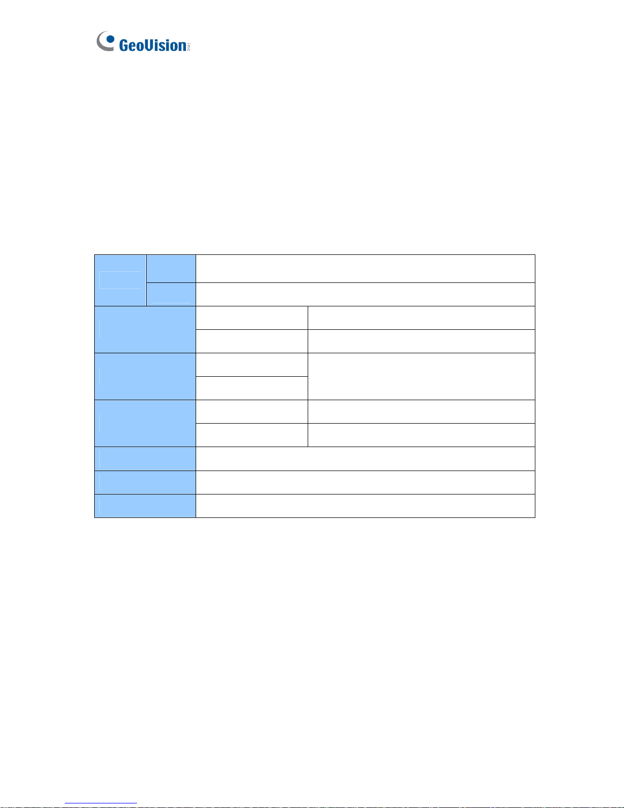
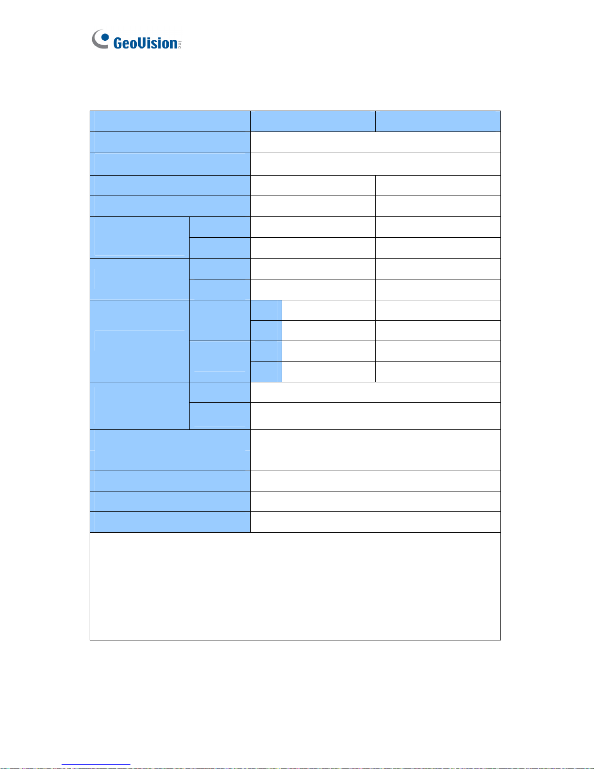
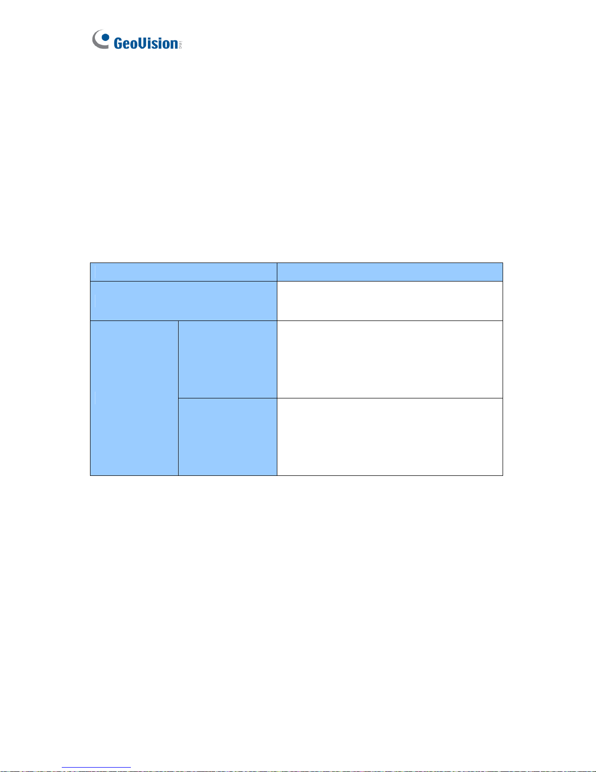
GPU Decoding Specifications
In V8.5.0.1, support for GPU (Graphics Processing Unit) decoding is added to lower the CPU
loading and to increase the total frame rate supported by a GV-System. GPU decoding only
supports the following software and hardware specifications:
Software Specifications
Supported Not Supported
Operating
System
Windows Vista (32-bit) / 7 (32 / 64-bit)
/ Server 2008 R2 (64-bit)
Windows 2000 / XP /
Server 2008 (32 / 64-bit)
Resolution
1 M / 2 M CIF / VGA / D1 / 3M / 4M / 5M
Codec
H.264 MPEG4 / MJEPG
Stream
Single Stream Dual Streams
Note: To apply GPU decoding, the recommended memory (RAM) requirements is 8 GB or
more for 64-bit OS and 3 GB for 32-bit OS.
Hardware Specifications
Motherboard
Sandy Bridge chipset with onboard VGA (external VGA cannot be
installed)
Ex: Intel® Q67, H67, H61, Q65, B65, Z68 Express Chipset.
Multi-Channel Playback Specifications
In V8.5.0.1, multi-channel playback in ViewLog has been enhanced to improve the
smoothness of the video by producing higher frame rate. However, playing back multiple
channels at high resolution can increase the CPU loading especially if the GV-System is
processing other tasks simultaneously. As a result of the high CPU loading, dropped frames
may sometimes occur in recorded video when playing back multiple megapixel channels.
To avoid the problem, it is recommended to play back megapixel video in single view.
Page 5

iii
Important Notice before Using GV-Video Capture Card
1. Exclusions:
• Currently GV-Video Capture Cards are not compatible with VIA-series, ATI-series
chipset motherboards.
• Currently GV-600A, GV-650A and GV-800A Cards are not compatible with VIA-series,
ATI-series and Intel Sandy Bridge series chipset motherboards.
• Currently GV-3008 Card is not compatible with VIA-series, ATI-series, Intel Sandy
Bridge series and NVIDIA-series chipset motherboards.
If your GV-Video Capture Card or GV-System works in conjunction with the following GV
accessories, note the limitation that these accessories do not support 64-bit Windows
versions currently: GV-Multi Quad Card, GV-Keyboard V1 / V2.
2. Hard Disk Requirements:
• It is strongly recommended to use two separate hard disks. One is for installing Windows
operating system and GV-System software, and the other is for storing recorded files.
• The total of recording frame rates that you can assign to a single hard disk is listed as
below:
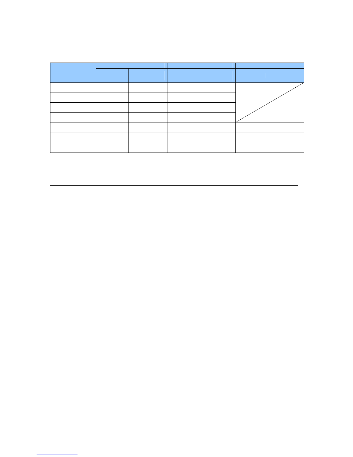
Frame rate limit in a single hard disk when connecting to analog cameras
Software Compression
MPEG4
Video resolution
NTSC PAL
CIF 480 fps 400 fps
VGA/D1 240 fps 200 fps
Turbo VGA 416 fps 400 fps
Turbo D1 352 fps 320 fps
Hardware Compression
H.264
Video resolution
NTSC PAL
D1 240 fps 200 fps
Page 6
iv
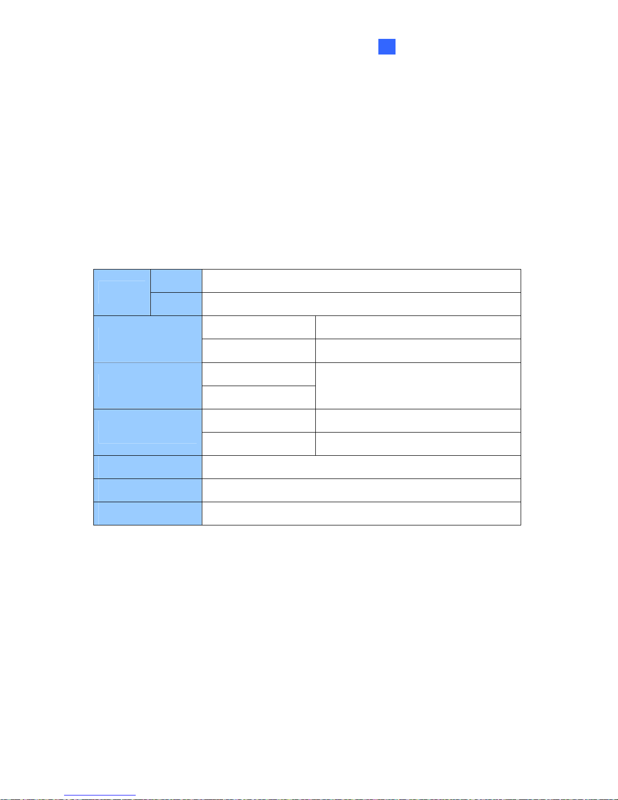
Frame rate limit in a single hard disk when connecting to IP cameras
MJPEG H.264 MPEG4
Video
Resolution
Frame Rate Bit Rate Frame Rate Bit Rate
Frame Rate Bit Rate
2560x1920 (5M) 30 fps 102.26 Mbit/s 240 fps
21.24 Mbit/s
2560x1600 (4M) 60 fps 73.49 Mbit/s 240 fps
15.28 Mbit/s
2048x1536 (3M) 60 fps 64.73 Mbit/s 480 fps
10.52 Mbit/s
1600x1200 (2M) 120 fps 41.16 Mbit/s 480 fps
9.16 Mbit/s
1280x960 (1.3M) 200 fps 30.04 Mbit/s 480 fps
5.77 Mbit/s 480 fps 6.30 Mbit/s
640x480 (VGA) 480 fps 11.42 Mbit/s 640 fps
2.54 Mbit/s 640 fps 3.27 Mbit/s
320x240 (CIF) 480 fps 5.16 Mbit/s 640 fps
0.75 Mbit/s 640 fps 1.03 Mbit/s
Note: The above data was determined using the bit rate listed above and hard disks with
average R/W speed above 80 MB/s.
The frame rate limit is based on the resolution of video sources. The higher video
resolutions the lower frame rates you can assign to a single hard disk. In other words, the
higher frame rates you wish to record the more hard disks you need to install. For the
information of recording frame rates, you may consult the user’s manual of the GV-
System or the IP camera that you wish to connect to.
• The hard disk space required to install GV-System must be at least 1 GB.
• To use Advance Video Analysis, at least 1 GB of memory is required.
• To use two or more of the following functions simultaneously, at least 2 GB of memory is
required: Advance Video Analysis, Video Analysis, IP Camera and Pre-Record by
Memory.
3. CPU Requirements:
• For recording resolution of 640 x 480 or above, Pentium 4 processor with Hyper
Threading is required.
4. Default Settings:
• For software recording rates, all GV Cards are set to CIF. For hardware recording rates,
GV-4008A / 4008 / 3008 Card is set to D1.
Page 7

v
5. The Card with PCI-E Interface:
• All GV-Video Capture Cards with PCI-E Interfaces have x1 interface which can be
inserted into the PCI Express x1, x4, x8 or x16 slot.
6. GV-600A, GV-650A and GV-800A:
• Starting from V8.3.2, GV-600 (V4), GV-650 (V4) and GV-800 (V4) are renamed to GV-
600A, GV-650A and GV-800A. These V4 Cards and A Cards are the same video capture
cards.
7. End of Support:
• Starting from V8.3, GV-System will not support GV-250 Card, GV-Hybrid DVR (MPEG2)
Card and GV-DSP Card.
• Starting from V8.3.2, GV-System will not support GV-2004 Card.
• Starting from V8.3.2, GV-System will not support MPEG2 codec.
• Starting form V8.3.3, GV-System will not support GV-2008 Card.
• Starting from V8.4, GV-System will not support Windows 2000.
Page 8

Page 9

Chapter 1 Video Capture Cards
This chapter includes the following information:
• Minimum system requirements
• Packing list
• Connection diagrams
• Specifications
• Driver installation
• Comparison chart
Page 10
2
1.1 GV-4008
The GV-4008 Card provides up to 8 video and 8 audio channels, recording up to 240 / 200
fps (NTSC / PAL) in total with H.264 hardware compression. The new technology of
resolution is employed to enhance the live image of D1 without DSP Overlay. Even in screen
divisions, the largest division can remain at the high-quality D1 resolution.
Minimum System Requirements
32-bit
Windows XP / Windows Vista / Windows 7 / Windows Server 2008
OS
64-bit
Windows 7 / Windows Server 2008
GV-4008 Core 2 Duo, 2.33 GHz
CPU
GV-4008 x 2 Core 2 Quad, 2.4 GHz
GV-4008
RAM
GV-4008 x 2
2 x 1 GB Dual Channels
GV-4008 250 GB
HDD
GV-4008 x 2 500 GB
VGA
ATI Radeon X1300 PCI-E / NVIDIA GeForce 7300 PCI-E
DirectX
9.0c
Power Supply
400 Watts
Packing List
1. GV-4008 Card x 1
2. 1-8 Cam Audio BNC Cable with BNC
Male to RCA Female Adaptors x 1
3. 1-8 Cam Video BNC Cable x 1
4. Hardware Watchdog Jumper Wire x1
5. SATA Power Converter Cable x 1
6. USB Dongle x 1
7. Software DVD x 1
8. Surveillance System Quick Start Guide x 1
Page 11

Video Capture Cards
3
1
Connecting One GV-4008 Card
• Connect the video and audio cables to the GV-4008 Card.
• Using the supplied SATA Power Converter Cable, connect the GV-4008 Card to power
supply. The Power LED in the top right corner should be lit in green and the 4 status
LEDs (D3, D9, D14, D18) in the left corner should be lit in green to indicate the normal
functionality.
Figure 1-1
Note:
1. The GV-4008 Card only works when the supplied USB Dongle is inserted to PC.
2. The GV-4008 Card cannot work with microphones which acquire power from the PC.
Use microphones which have external power supply.
Page 12
4
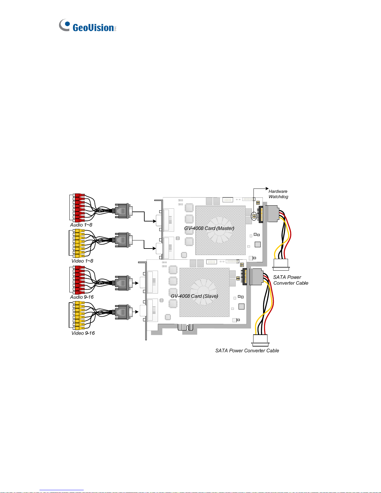
Connecting Two GV-4008 Cards
You can install two GV-4008 Cards for a total of 16 channels. Master Card is the card with 1-
8 channels and Slave Card is that with 9-16 channels. Normally, the card attached to the
lower PCI slot number will act as Master, and the card attached to the higher PCI slot
number will act as Slave.
• Hardware Watchdog Connection: Connect the supplied Hardware Watchdog Jump
Wire to the Master Card only (Figure 1-3).
• Accessory Card Connections: To work together with GV-4008 Cards, GV-NET/IO Card
V3.1 must be set in the I/O Box Mode and connected to the PC through USB.
Figure 1-2
Page 13
Video Capture Cards
5
1
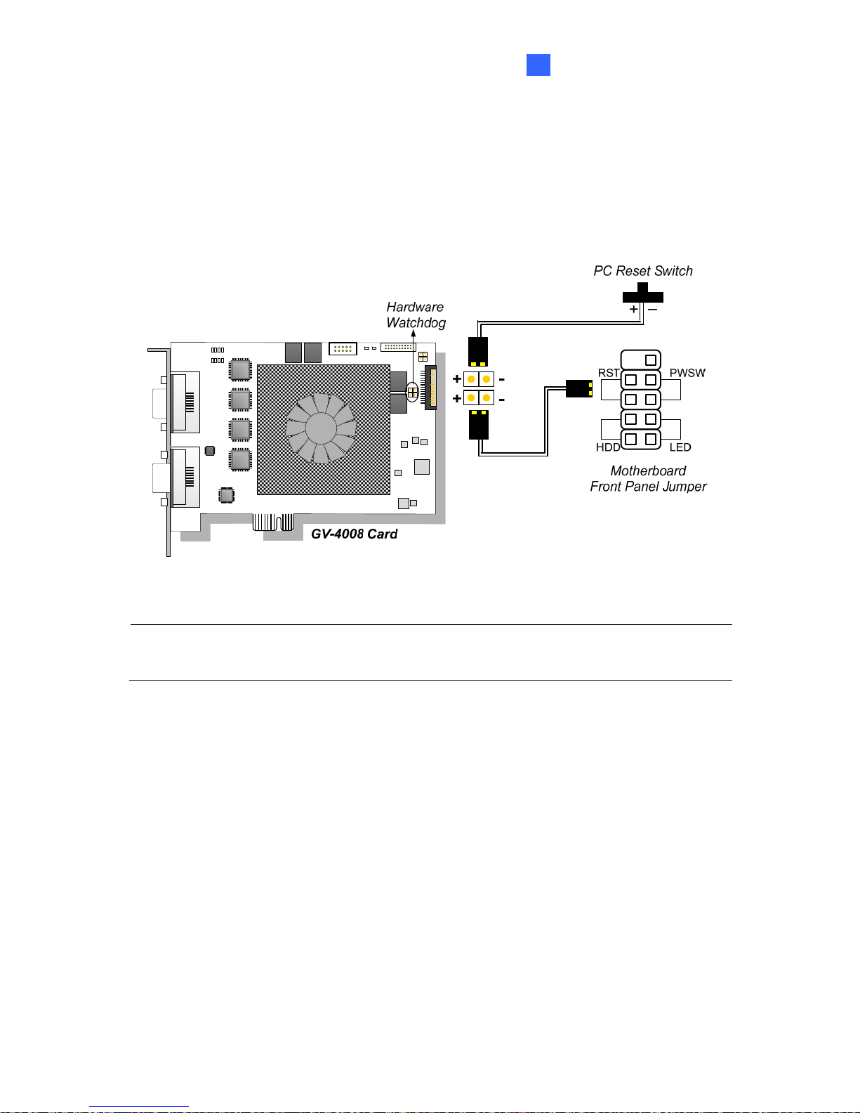
Connecting Hardware Watchdog
Insert the Hardware Watchdog Jumper Wire to the 2-pin connectors on the Card. The (+) pin
on the Card must connect to the Reset (+) pin on the motherboard, and the (-) pin on the
Card to the Ground (-) pin on the motherboard. Ensure the connection is correct; otherwise
the hardware watchdog will be damaged.
Figure 1-3
Note: To locate the motherboard’s Reset (+) pin and (-) pin, please refer to the
motherboard’s user manual.
Page 14
6
Installing Drivers
After installing the GV-4008 Card in the computer, insert the software DVD to install GV-
Series drivers. The DVD will run automatically and an installation window will pop up. Select
Install or Remove GeoVision GV-Series Driver, and select the following two options to
install card and USB dongle drivers.
• Install or Remove GeoVision GV-Series Card Drivers: installs card drivers.
• Install GeoVision USB Device Drivers: installs USB dongle drivers.
Note: For the installation of two GV-4008 cards, it is required to restart the computer after
the driver is installed.
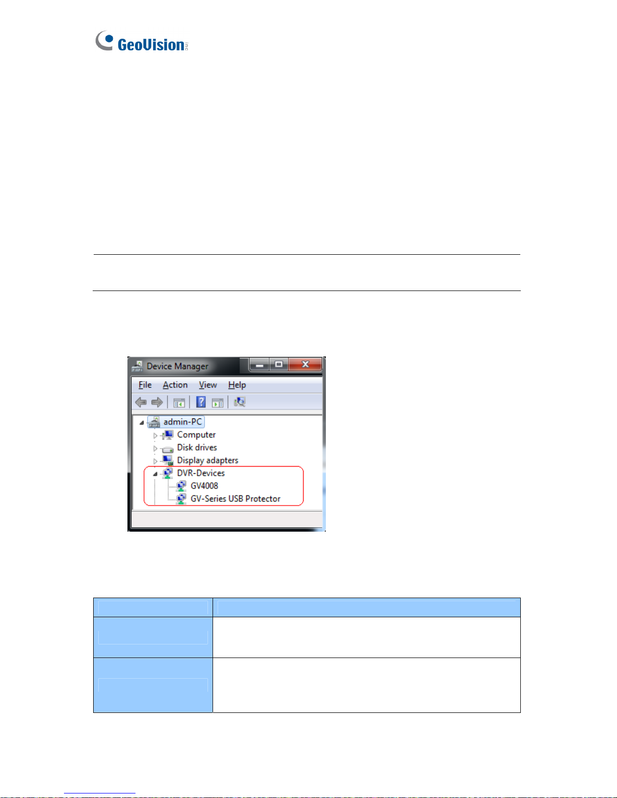
To verify the drivers are installed correctly, go to Windows Device Manager and see if their
entries are listed. The image below is an example of installing one GV-4008 card.
Figure 1-4
Expand the DVR-Devices field, you can see:
GV-4008 Card Entry
Single-card mode
GV4008
GV-Series USB Protector
Two-card mode
GV4008
GV4008
GV-Series USB Protector
Page 15

Video Capture Cards
7
1
Troubleshooting Power Supply Issues
When the Reset LED on the top of the Card is flashing red color or the four Status LEDs are
not all on, it indicates that the GV-4008 Card is short of power supply. Make sure your power
supply is of 400 watts at least. If not, replace it with the power supply of 400 or larger watts.
The power supply issues should be solved.
Adjusting the Video Settings in the Main System
One distinct feature of GV-4008 Cards is their ability of hardware compression, providing you
with higher system performance and DVD recording quality.
To take full advantage of GV-4008 Cards, you can adjust the video settings, including the
recording quality and frame rate, before running the GV-System.
Setting up the video settings of the recorded files:
Considering computer performance or recording quality, you may adjust the settings to meet
your needs.
1. On the Main System, click the Configure button, select System Configure, select
Camera Install, and click Hardware Compression Setup. This dialog box appears.
Figure 1-5
Page 16
8
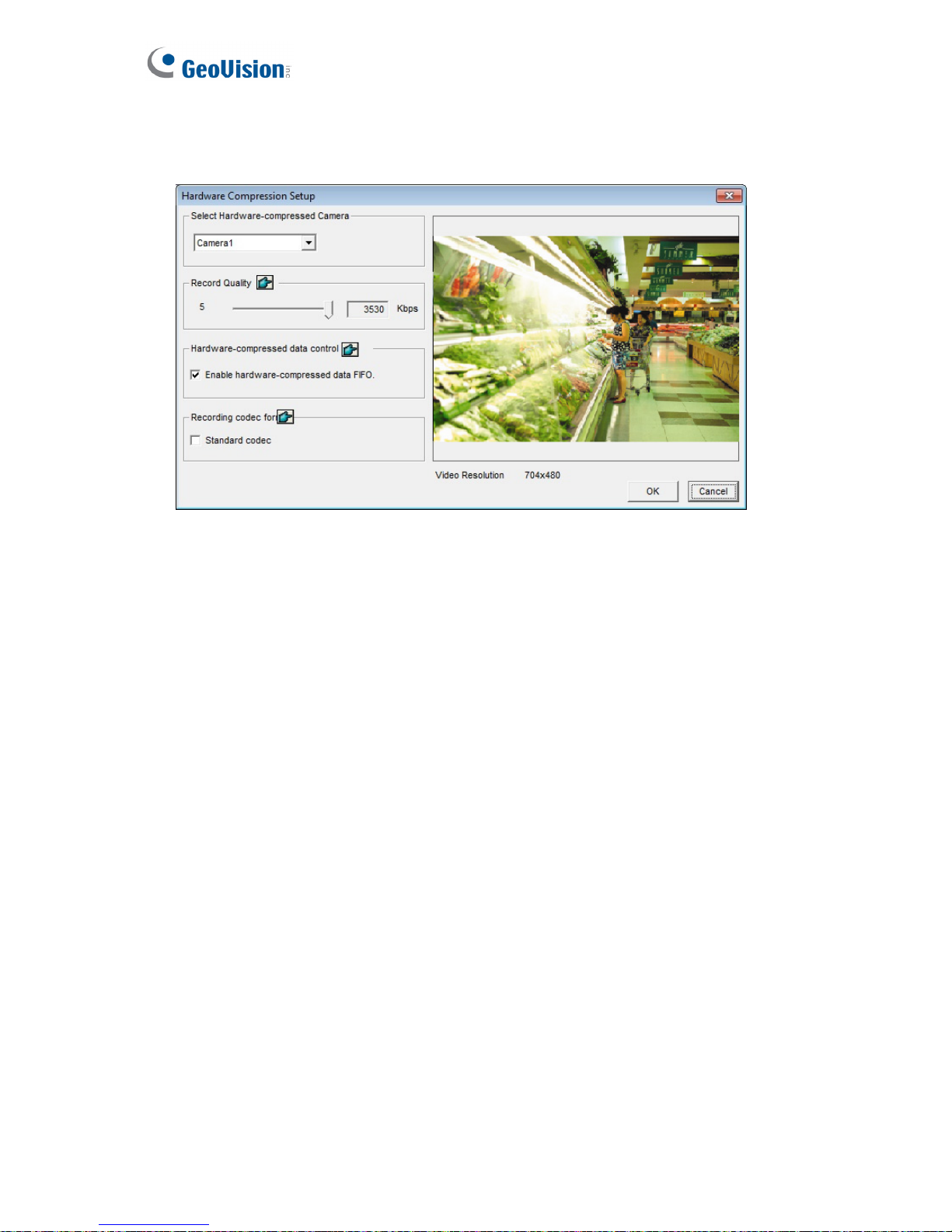
2. Select the cameras you want to set up, and click the Configure button. This dialog box
appears.
Figure 1-6
3. In the Select Hardware-compressed Camera section, select one camera to be configured.
4. Select the recording quality.
5. The Enable hardware-compressed data FIFO option is disabled by default. When the
option is enabled, the hardware-compressed data from the video IP device, such as IP
camera, video server and compact DVR, will be transmitted directly to remote servers
instead of being compressed again on the DVR. The remote servers include CMS-related
servers and WebCam Server. This feature can decrease the system load of DVR but
increase that of remote servers.
6. To use standard H.264 codec in recording, enable Standard codec in the Recording
codec for section.
7. If you want to apply the same setting to all cameras, click the Finger button in each
section.
Page 17
Video Capture Cards
9
1
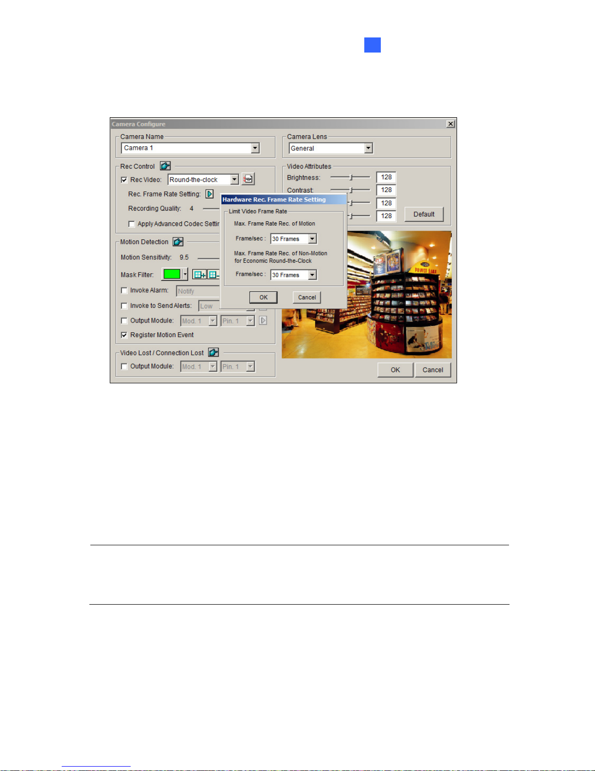
8. To access the frame rate settings, on the Main System, click the Configure button, select
System Configure, and select Camera Configure. This dialog box appears.
Figure 1-7
9. In the Rec Control section, click the Arrow button. The Hardware Rec. Frame Rate
Setting dialog box appears.
10. Set the maximum frame rate for motion and non-motion periods so as to save as much
disk space as possible.
11. To adjust image quality, in the Video Attributes section, move the sliders to the desired
values or click Default to apply default values.
Note: The default settings are as follows: Recording Quality is 3, Video Resolution is 704 x
480 (NTSC) or 704 x 576 (PAL), Codec is Geo H.264 and Frame Rate is 30 (NTSC) or 25
(PAL).
Page 18
10
Specifications
GV-4008 GV-4008 x 2
Interface PCI-E x1
Input Type DVI
Video Input 8 Cams 16 Cams
Audio Input 8 Channels 16 Channels
NTSC 240 fps 480 fps
Recording Rate
(D1)
PAL 200 fps 400 fps
NTSC 240 fps 480 fps
Display Rate
PAL 200 fps 400 fps
H/W 704 x 480 704 x 480
NTSC
S/W 352 x 240 352 x 240
H/W 704 x 576 704 x 576
Video Resolution
PAL
S/W 352 x 288 352 x 288
S/W Geo MPEG4, Geo H264
Video Compression
Format
H/W H.264
Audio Compression Format AAC (16 kHz / 16 bit)
Bit Rate Range 2.5M ~ 5M
GV-NET/IO Card Support Yes (Note2)
GV-Multi Quad Card Support No
Dimensions (W x H) 169 x 99 mm / 6.65 x 3.9 in
Note:
1. GV-4008 does not support the TV-Out function.
2. To work together with GV-4008, GV-NET/IO Card V3.1 must be set in the I/O Box
Mode and connected to the PC through USB.
3. In screen divisions, the largest division is set to D1 resolution and the other divisions
to CIF resolution.
Page 19
Video Capture Cards
11
1
1.2 GV-4008A
The GV-4008A Card provides up to 8 video and 8 audio channels, recording up to 240 / 200
fps (NTSC / PAL) in total with H.264 hardware compression. The new technology of
resolution is employed to enhance the live image without DSP Overlay. Even in multi views,
the image on the largest division view can remain at the high-quality resolution without DSP
Overlay.
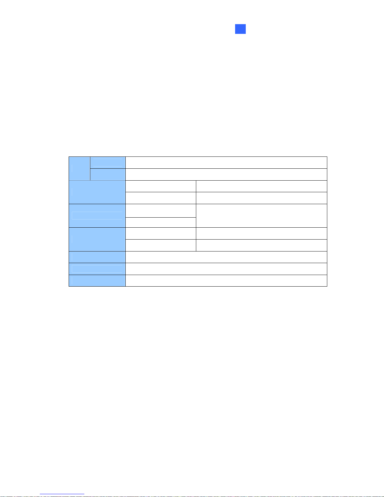
Minimum System Requirements
32-bit Windows XP / Windows Vista / Windows 7 / Windows Server 2008
OS
64-bit Windows 7 / Windows Server 2008
GV-4008A Core 2 Duo, 2.33 GHz
CPU
GV-4008A x 2 Core 2 Quad, 2.4 GHz
GV-4008A
RAM
GV-4008A x 2
2 x 1 GB Dual Channels
GV-4008A 250 GB
HDD
GV-4008A x 2 500 GB
VGA ATI Radeon X1300 PCI-E / NVIDIA GeForce 7300 PCI-E
DirectX 9.0c
Power Supply 400 Watts
Packing List
1. GV-4008A Card x 1
2. 1-8 DVI-Type Audio Cable x 1
3. 1-8 DVI-Type Video Cable x 1
4. Hardware Watchdog Jumper Wire x 1
5. Internal Power Y Cable x 1
6. USB Dongle x 1
7. Software DVD x 1
8. Surveillance System Quick Start Guide x 1
Page 20

12
Connecting One GV-4008A Card
• Connect the video and audio cables to the GV-4008A Card.
• Connect the supplied Hardware Watchdog Jump Wire (Figure 1-10).
• Connect the computer’s internal power supply to the GV-4008A Card. The LEDs (D17,
D19, D21, D23) should be lit in green to indicate the card is ready for use.
Figure 1-8
Note:
1. The GV-4008A Card only works when the supplied USB Dongle is inserted to PC.
2. The GV-4008A Card cannot work with microphones which acquire power from the
PC. Use microphones which have external power supply.
Page 21
Video Capture Cards
13
1
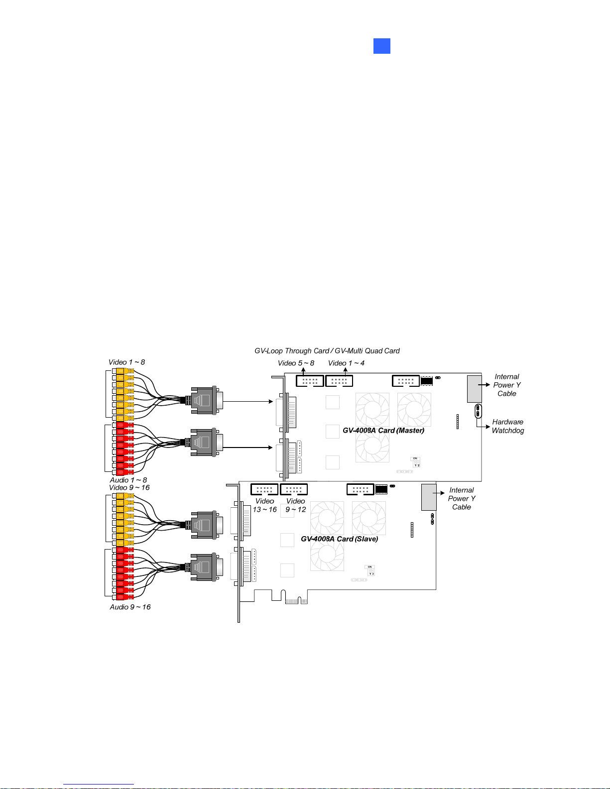
Connecting Two GV-4008A Cards
You can install two GV-4008A Cards for a total of 16 channels. Master Card is the card with
1-8 channels and Slave Card is that with 9-16 channels. Normally, the card attached to the
lower PCI-E slot number will act as Master, and the card attached to the higher PCI-E slot
number will act as Slave.
• Hardware Watchdog Connection: Connect the supplied Hardware Watchdog Jump
Wire to the Master Card only (Figure 1-10).
• Accessory Card Connections:
GV-Loop Through Card: Connect the card to two 10-pin connectors on each
Master and Slave Card by using a supplied cable with four 10-pin headers.
GV-Multi Quad Card: Connect the card to two 10-pin connectors on each Master
and Slave Card by using a supplied cable with four 10-pin headers.
Figure 1-9
Page 22
14
Connecting Hardware Watchdog
Insert the Hardware Watchdog Jumper Wire to the 2-pin connectors on the Card. The (+) pin
on the Card must connect to the Reset (+) pin on the motherboard, and the (-) pin on the
Card to the Ground (-) pin on the motherboard. Ensure the connection is correct; otherwise
the hardware watchdog will not work.
++
Figure 1-10
Note: To locate the motherboard’s Reset (+) pin and (-) pin, please refer to the
motherboard’s user manual.
Page 23
Video Capture Cards
15
1
Installing Drivers
After installing the GV-4008A Card in the computer, insert the software DVD to install GV-
Series drivers. The DVD will run automatically and an installation window will pop up. Select
Install or Remove GeoVision GV-Series Driver, and select the following two options to
install card and USB dongle drivers.
• Install or Remove GeoVision GV-Series Card Drivers: installs card drivers.
• Install GeoVision USB Device Drivers: installs USB dongle drivers.
To verify the drivers are installed correctly, go to Windows Device Manager and see if their
entries are listed.
Expand the DVR-Devices field, you can see:
GV-4008A Card Entry
Single-card mode
GV4008(A)
GV-Series USB Protector
Two-card mode
GV4008(A)
GV4008(A)
GV-Series USB Protector
Adjusting the Video Settings in the Main System
One distinct feature of GV-4008A Cards is their ability of hardware compression, providing
you with higher system performance and DVD recording quality.
To take full advantage of GV-4008A Cards, you can adjust the video settings, including the
recording quality and frame rate, before running the GV-System.
For details on adjusting the video settings, see Setting up the video settings of the recorded
files in 1.1 4008 Card.
Page 24
16
Specifications
GV-4008A GV-4008A x 2
Interface PCI-E x1
Input Type DVI
Video Input 8 Cams 16 Cams
Audio Input 8 Channels 16 Channels
NTSC 240 fps 480 fps
Recording Rate
(D1)
PAL 200 fps 400 fps
NTSC 240 fps 480 fps
Display Rate
PAL 200 fps 400 fps
H/W 704 x 480 704 x 480
NTSC
S/W 352 x 240 352 x 240
H/W 704 x 576 704 x 576
Video Resolution
PAL
S/W 352 x 288 352 x 288
S/W
Geo MPEG4, Geo H264
Video
Compression
Format
H/W H.264
Audio Compression Format AAC (16 kHz / 16 bit)
Bit Rate Range 2.5M ~ 5M
GV-NET/IO Card Support Yes (Note 2)
GV-Multi Quad Card Support Yes
GV-Loop Through Card Support Yes
Dimensions (W x H) 169 x 112 mm / 6.65 x 4.41 in
Note:
1. GV-4008A does not support the TV-Out function.
2. To work together with GV-4008A, GV-NET/IO Card V3.1 must be set in the I/O Box
Mode and connected to the PC through USB.
Page 25
Video Capture Cards
17
1
1.3 GV-3008
The GV-3008 Card provides up to 8 video and 8 audio channels, recording up to 240 / 200
fps (NTSC / PAL) in total with H.264 hardware compression. The GV-3008 Card provides the
high-resolution live image with DSP Overlay. Even in multi views, the image on the largest
division view can remain at the high-quality resolution.
Minimum System Requirements
32-bit
Windows XP / Windows Vista / Windows 7 / Windows Server 2008
OS
64-bit
Windows 7 / Windows Server 2008
GV-3008 Core 2 Duo, 2.33 GHz
CPU
GV-3008 x 2 Core 2 Quad, 2.4 GHz
GV-3008
RAM
GV-3008 x 2
2 x 1 GB Dual Channels
GV-3008 250 GB
HDD
GV-3008 x 2 500 GB
VGA
ATI Radeon X1300 PCI-E / NVIDIA GeForce 7300 PCI-E
DirectX
9.0c
Power Supply
400 Watts
Packing List
1. GV-3008 Card x 1
2. 1-4 D-Type Video and Audio Cable x 1
3. 5-8 D-Type Video and Audio Cable x 1
4. Hardware Watchdog Jumper Wire x1
5. Software DVD x 1
6. Surveillance System Quick Start Guide x 1
Page 26

18
Connecting One GV-3008 Card
• Connect the D-Type video and audio cables to the GV-3008 Card.
• Connect the supplied Hardware Watchdog Jump Wire (Figure 1-13).
• Connect the computer’s internal power supply to the GV-3008 Card. The Power LED
should be lit in green to indicate the card is ready for use.
Figure 1-11
Page 27

Video Capture Cards
19
1
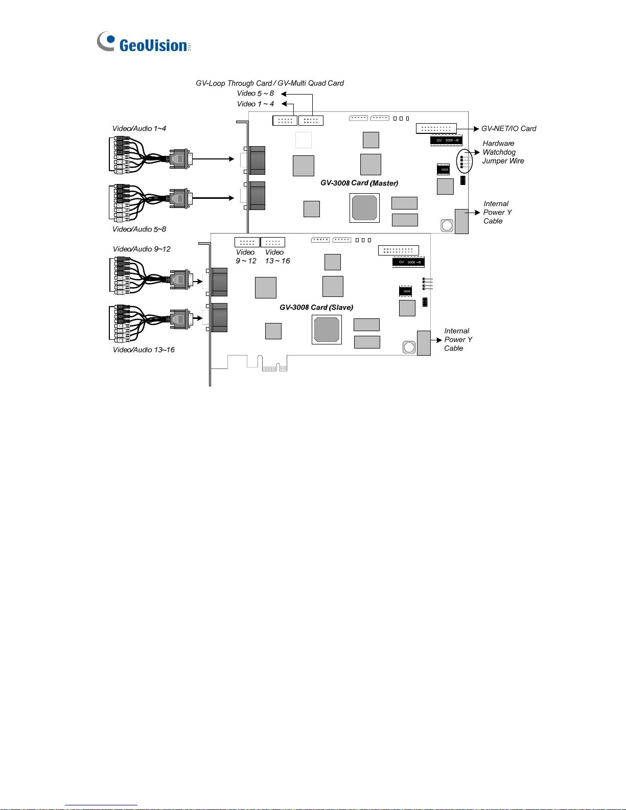
Connecting Two GV-3008 Cards
You can install two GV-3008 Cards for a total of 16 channels. Master Card is the card with 1-
8 channels and Slave Card is that with 9-16 channels. The Master and Slave cards can be
distinguished by the labels on cards, as shown below:
Master Card:
Slave Card:
IMPORTANT:
1. The Slave Cards cannot work alone. They need to work in conjunction with the Master
Cards.
2. If both GV-3008 Cards are Master Cards, it is required to identify which are Master
and Slave by the PCI-E slot number. Normally, the card attached to the lower PCI-E
slot number will act as Master, and the card attached to the higher PCI-E slot number
will act as Slave.
• Hardware Watchdog Connection: Connect the supplied Hardware Watchdog Jump
Wire to the Master Card only (Figure 1-13).
• Accessory Card Connections:
GV-NET/IO Card: Connect the card only to the Master Card.
GV-Loop Through Card: Connect the card to two 10-pin connectors on each
Master and Slave Card by using a supplied cable with four 10-pin headers.
GV-Multi Quad Card: Connect the card to two 10-pin connectors on each Master
and Slave Card by using a supplied cable with four 10-pin headers.
Page 28
20
Figure 1-12
Page 29
Video Capture Cards
21
1
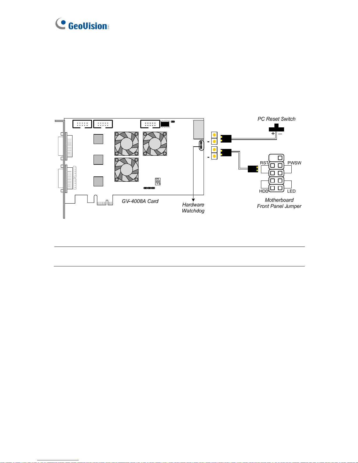
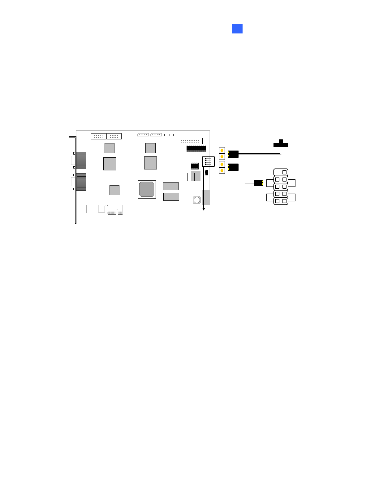
Connecting Hardware Watchdog
To restart the computer automatically by the hardware watchdog on the GV-Video Capture
Card, a connection needs to be made from the card to the motherboard.
1. Using the supplied jumper wire, connect the reset jumper pins on the card and on the
motherboard.
PWSW
LEDHDD
RST
Motherboard
Front Panel Jumper
PC Reset Switch
GV 3008 - 8
3008
GV-3008 Card
Hardware
Watchdog
Figure 1-13
2. If the computer has a reset switch, the switch’s jumper wire should already be connected
to the motherboard’s reset jumper pins. Remove the switch wire from the motherboard
and connect it to the reset jumper pins on the card.
Page 30
22
Installing Drivers
After installing the GV-3008 Card in the computer, insert the software DVD to install GV-
Series drivers. The DVD will run automatically and an installation window will pop up. Select
Install or Remove GeoVision GV-Series Driver, and select Install or Remove GeoVision
GV-Series Card Drivers to install card drivers.
To verify the drivers are installed correctly, go to Windows Device Manager and see if their
entries are listed.
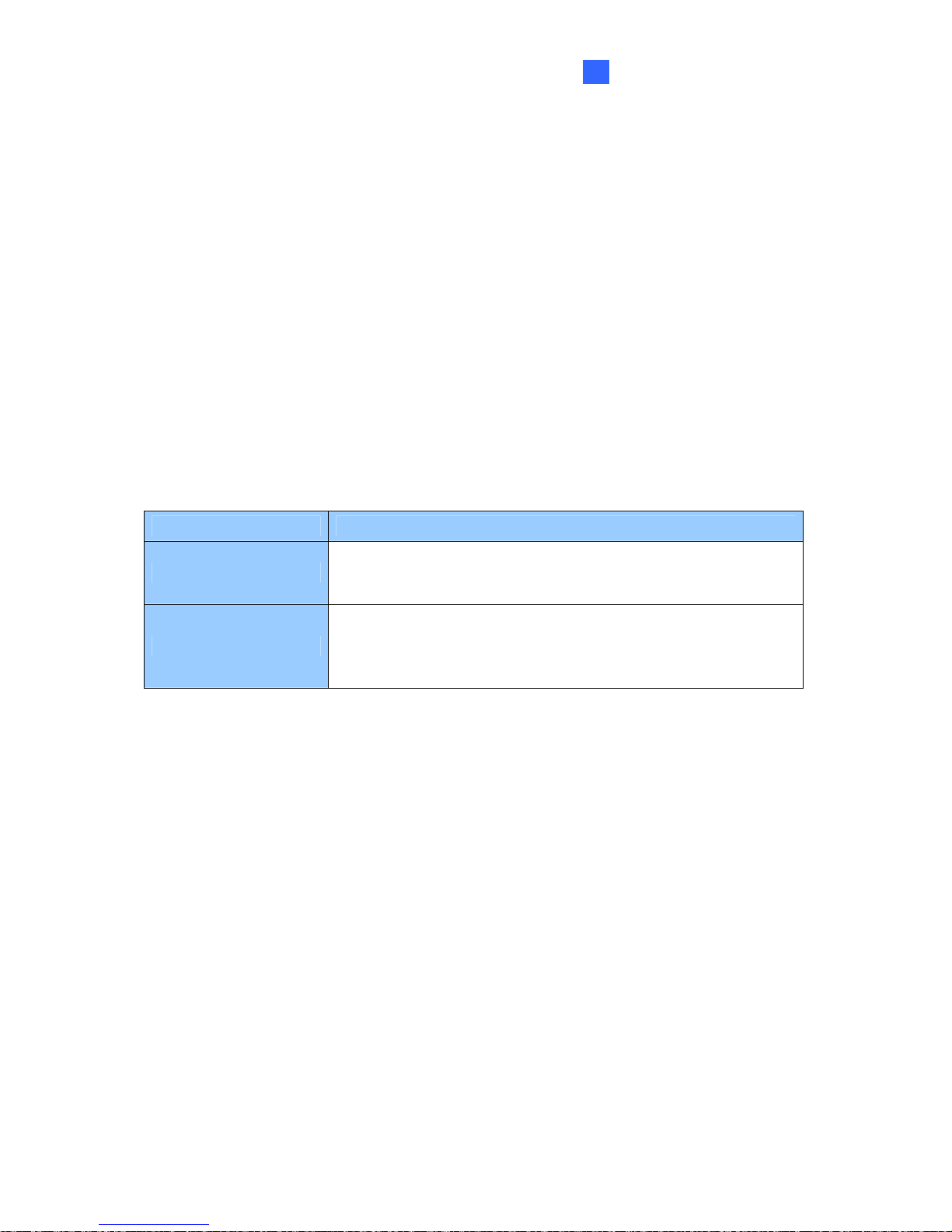
Expand the DVR-Devices field, you can see:
GV-3008 Card Entry
Single-card mode
GV3008 Capture
GV3008 Encode #1
GV3008 Encode #2
Two Master Cards
GV3008 Capture
GV3008 Capture
GV3008 Encode #1
GV3008 Encode #1
GV3008 Encode #2
GV3008 Encode #2
Two-card mode
One Master and
Slave Card
GV3008 Capture
GV3008 Capture
GV3008 Encode #1
GV3008 Encode #2
GV3008 Encode #3
GV3008 Encode #4
Adjusting the Video Settings in the Main System
One distinct feature of GV-3008 Cards is their ability of hardware compression, providing you
with higher system performance and DVD recording quality.
To take full advantage of GV-3008 Cards, you can adjust the video settings, including the
recording quality and frame rate, before running the GV-System.
For details on adjusting the video settings, see Setting up the video settings of the recorded
files in 1.1 4008 Card.
Page 31

Video Capture Cards
23
1
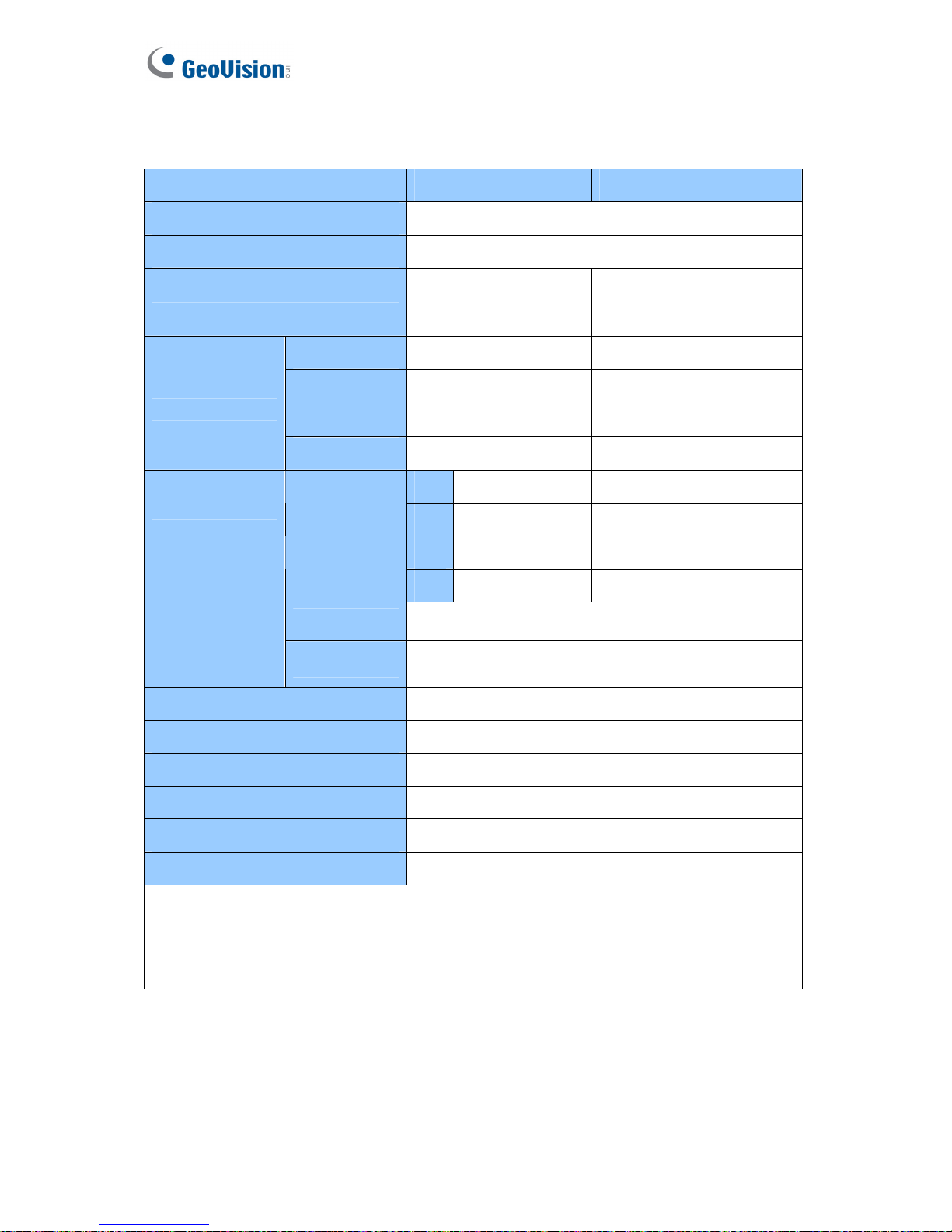
Specifications
GV-3008 GV-3008 x 2
Interface PCI-E x1
Input Type D-Type
Video Input 8 Cams 16 Cams
Audio Input 8 Channels 16 Channels
NTSC 240 fps 480 fps
Recording Rate (D1)
PAL 200 fps 400 fps
NTSC 240 fps 480 fps
Display Rate
PAL 200 fps 400 fps
H/W 704 x 480 704 x 480
NTSC
S/W 352 x 240 352 x 240
H/W 704 x 576 704 x 576
Video Resolution
PAL
S/W 352 x 288 352 x 288
S/W Geo MPEG4, Geo H264
Video Compression
Format
H/W H.264
Audio Compression Format AAC (16 kHz / 16 bit)
Bit Rate Range 2.5M ~ 10M
GV-NET/IO Card Support Yes
GV-Multi Quad Card Support Yes
GV-Loop Through Card Support Yes
Dimensions (W x H) 180 x 112 mm / 7.09 x 4.41 in
Note: GV-3008 does not support the TV-Out function.
Page 32

24
1.4 GV-1120A, 1240A, 1480A
GV-Combo A Card (GV-1120A, GV-1240A and GV-1480A) are the three-in-one combo cards,
providing one single card solution for 16 video / audio recording, real-time display and TV-out
display.
Minimum System Requirements
32-bit
Windows XP / Windows Vista / Windows 7 / Windows Server 2008
OS
64-bit
Windows 7 / Windows Server 2008
Pentium 4, 3.0 GHz with Hyper-Threading
GV-1120A
Turbo Mode: Pentium 4, 3.0 GHz, Dual Core
Pentium 4, 3.0 GHz, Dual Core
GV-1120A x 2
Turbo Mode: Core 2 Quad, 2.4 GHz
Pentium 4, 3.0 GHz, Dual Core
GV-1240A
Turbo Mode: Core 2 Duo, 3.0 GHz
Core 2 Duo, 2.53 GHz
GV-1240A x 2
Turbo Mode: Core 2 Quad, 2.8 GHz
Core 2 Duo, 3.0 GHz
GV-1480A
Turbo Mode: Core 2 Quad, 2.4 GHz
Core 2 Quad, 2.4 GHz
CPU
GV-1480A x 2
Turbo Mode: Core i7-920, 2.66 GHz
Windows XP 2 x 512 MB Dual Channels
GV-1120A / 1240A / 1480A
Windows Vista /
7 / Server 2008
2 x 1 GB Dual Channels
RAM
GV-1120A x 2 / 1240A x 2 /
1480A x 2
2 x 1 GB Dual Channels
GV-1120A 80 GB / Turbo Mode: 120 GB
GV-1120 A x 2 160 GB / Turbo Mode: 250 GB
GV-1240A 120 GB / Turbo Mode: 160 GB
GV-1240A x 2 250 GB / Turbo Mode: 320 GB
GV-1480A 250 GB / Turbo Mode: 320 GB
HDD
GV-1480A x 2 500 GB / Turbo Mode: 750 GB
VGA
ATI Radeon X1300 PCI-E / NVIDIA GeForce 7300 PCI-E
DirectX
9.0c
Page 33

Video Capture Cards
25
1
Packing List (D-Type)
1. GV-Combo A Card x 1
2. Audio Extension Card x 1
3. 1-8 D-Type Video Cable x 1
4. 9-16 D-Type Video Cable x 1
5. 1-8 D-Type Audio Cable x 1
6. 9-16 D-Type Audio Cable x 1
7. Internal Power Y Cable x 1
8. Hardware Watchdog Jumper Wire x 1
9. Software DVD x 1
10. Surveillance System Quick Start Guide x 1
Packing List (DVI-Type)
1. GV- Combo A Card x 1
2. 1-8 DVI-Type Video plus TV Out Cable x 1
3. 9-16 DVI-Type Video Cable x 1
4. 1-8 DVI-Type Audio Cable x 1
5. 9-16 DVI-Type Audio Cable x 1
6. Internal Power Y Cable x 1
7. Hardware Watchdog Jumper Wire x 1
8. Software DVD x 1
9. Surveillance System Quick Start Guide x 1
Page 34

26
Connecting One GV-Combo A Card (D-Type)
• Plug the Audio Extension Card in the assigned connectors on the GV-Combo A Card.
• Connect D-Type video and audio cables to the GV-Combo A Card and Audio
Extension Card respectively.
• Connect the supplied Hardware Watchdog Jump Wire (Figure 1-18).
• Connect the PC’s internal power supply to the GV-Combo A Card.
• Connect the TV monitor to the GV-Combo A Card if needed.
Figure 1-14
Note: The Card only works when it connects to PC’s power supply using the supplied
Internal Power Y Cable.
Page 35

Video Capture Cards
27
1
Connecting One GV-Combo A Card (DVI-Type)
• Connect the DVI video and audio cables to the GV-Combo A Card.
• Connect the supplied Hardware Watchdog Jump Wire (Figure 1-18).
• Connect the PC’s internal power supply to the GV-Combo A Card.
• Connect the DVI TV Out cable to the TV monitor if needed.
TV Monitor
GV-Combo A Card
1-16 DVI Video Cable
1-16 DVI Audio Cable
DVI TV Out
Cable
Internal
Power Y
Cable
Hardware
Watchdog
GV-Loop Through Card /
GV-Multi Quad Card
GV-NET/IO Card
Figure 1-15
Note: The Card only works when it connects to PC’s power supply using the supplied
Internal Power Y Cable.
Page 36

28
Connecting GV-NET/IO Card to GV-Combo A Card
Connect the GV-NET/IO Card to the 20-pin GV-NET/IO port on the GV-Combo A Card.
Some GV-Combo A Cards are built in two 20-pin ports. Ensure to connect the GV-NET/IO
Card to the correct port as illustrated below.
Figure 1-16
Note: If the GV-NET/IO Card is connected to the Debug port, it may lead to the GV-NET/IO
Card to be damaged, or the GV-Combo A Card to burn out, causing Video Lost or an error
message of “can’t find keypro” to pop up.
Page 37

Video Capture Cards
29
1
Connecting Two GV-Combo A Cards
You can install two GV-Combo A Cards of the same model for up to 32 channels. Master
Card is the card with 1-16 channels and Slave Card is that with 17-32 channels. Normally,
the card attached to the lower PCI-E slot number will act as Master, and the card attached to
the higher PCI-E slot number will act as Slave.
• TV Output Connection: The RCA connector in the Master Card is for displaying 1-16
channels, and the one in the Slave Card is for displaying 17-32 channels.
• Hardware Watchdog Connection: Connect the supplied Hardware Watchdog Jump Wire
to the Master Card only (Figure 1-18).
• Accessory Card Connections:
GV-NET/IO Card: Connect the card only to the Master Card.
GV-Loop Through Card: Connect the card for each video capture card.
GV-Multi Quad Card: Only connect one card to any of two video capture cards.
1
2
3
4
GV-Combo A Card
(Ma ster)
1
2
3
4
GV-C ombo A Card
(Sla ve )
1
2
3
4
Internal
Power Y
Cable
TV Monitor
Audio Extension Card
1-8 D-Type
Video Cable
9-16 D- Type
Video Cable
1-8 D-Type
Audio Cable
9-16 D- Type
Audio Cable
Internal
Power Y
Cabl e
17-24 D-Type
Video Cable
25-32 D-Type
Video Cable
TV Monitor
17-24 D-Type
Audio Cable
25-32 D-Type
Audio Cable
1
2
3
4
Audio Extension Card
Hardware
Watchdog
Jump Wire
Hardware
Watchdog
Jum p Wire
GV-NET/IO Card
GV-Loop Through Card /
GV-Multi Quad Card
Figure1-17
Page 38

30
Connecting Hardware Watchdog
Insert the Hardware Watchdog Jumper Wire to the 2-pin connectors on the Card and on the
motherboard as illustrated below. Ensure the connection is correct; otherwise the hardware
watchdog will not work.
Figure 1-18
Page 39

Video Capture Cards
31
1
Installing Drivers
After installing the GV-Combo A Card in the computer, insert the software DVD. The DVD
will run automatically and an installation window will pop up. Select Install or Remove
GeoVision GV-Series Driver, and select Install or Remove GeoVision GV-Series Card
Drivers to install card drivers.
To verify the drivers are installed correctly, go to Windows Device Manager and see if their
entries are listed.
Expand the DVR-Devices field, you can see:
Card Model Entry
Single-card mode
GV1480A/GV1240A/GV1248A/GV1120A/GV1008
GV-1120A
Two-card mode
GV1480A/GV1240A/GV1248A/GV1120A/GV1008
GV1480A/GV1240A/GV1248A/GV1120A/GV1008
Single-card mode GV1480A/GV1240A/GV1248A/GV1120A/GV1008
GV-1240A
Two-card mode
GV1480A/GV1240A/GV1248A/GV1120A/GV1008
GV1480A/GV1240A/GV1248A/GV1120A/GV1008
Single-card mode GV1480A/GV1240A/GV1248A/GV1120A/GV1008
GV-1480A
Two-card mode
GV1480A/GV1240A/GV1248A/GV1120A/GV1008
GV1480A/GV1240A/GV1248A/GV1120A/GV1008
Page 40

32
Specifications
GV-1120A GV-1240A GV-1480A
Interface Type
PCI-E x1
Input Type
D-Type, DVI
Video Input
8, 12, 16 Cams 8, 16 Cams 16 Cams
Audio Input
8, 12, 16 Channels 8, 16 Channels 16 Channels
TV Output
D-Type: RCA Connector
DVI: BNC Connector
NTSC
120 fps 240 fps 480 fps
CIF
PAL
100 fps 200 fps 400 fps
NTSC
80 fps 120 fps 240 fps
D1
PAL
72 fps 100 fps 200 fps
NTSC
120 fps 240 fps 416 fps
Turbo
VGA
PAL
100 fps 200 fps 400 fps
NTSC
120 fps 240 fps 352 fps
Recording
Rate
Turbo
D1
PAL
100 fps 200 fps 320 fps
NTSC
480 fps
CIF
PAL
400 fps
NTSC
480 fps
Display
Rate
D1
PAL
400 fps
NTSC
704 x 480, 704 x 480 De-interlace, 640 x 480,
640 x 480 De-interlace, 352 x 240, 320 x 240
Video Resolution
PAL
704 x 576, 704 x 576 De-interlace, 640 x 480,
640 x 480 De-interlace, 352 x 288, 320 x 240
Video Compression Format
Geo MPEG4, Geo H264
Audio Compression Format
AAC (16 kHz / 16 bit)
GV-Multi Quad Card Support
Yes
GV-Loop Through Card Support
Yes
GV-NET/IO Card Support
Yes
D-Type
Dimensions
DVI-Type
179 x 112 mm / 7.04 x 4.41 in
Note: Turbo Mode is only applied in VGA and D1 resolutions. To activate Turbo Mode, see
Activating Turbo Mode, Chapter 1, DVR User’s Manual on the Software DVD.
Page 41

Video Capture Cards
33
1
GV-1120A x 2 GV-1240A x 2 GV-1480A x 2
Interface Type
PCI-E x1
Input Type
D-Type, DVI
Video Input
16, 20, 24, 28, 32
Cams
16, 24, 32 Cams 32 Cams
Audio Input
16, 20, 24, 28, 32
Channels
16, 24, 32
Channels
32 Channels
TV Output
D-Type: RCA Connector
DVI: BNC Connector
NTSC
240 fps 480 fps 960 fps
CIF
PAL
200 fps 400 fps 800 fps
NTSC
160 fps 240 fps 480 fps
D1
PAL
144 fps 200 fps 400 fps
NTSC
240 fps 480 fps 832 fps
Turbo
VGA
PAL
200 fps 400 fps 800 fps
NTSC
240 fps 480 fps 704 fps
Recording
Rate
Turbo
D1
PAL
200 fps 400 fps 640 fps
NTSC
960 fps 960 fps 960 fps
CIF
PAL
800 fps 800 fps 800 fps
NTSC
960 fps 960 fps 960 fps
Display
Rate
D1
PAL
800 fps 800 fps 800 fps
NTSC
704 x 480, 704 x 480 De-interlace, 640 x 480,
640 x 480 De-interlace, 352 x 240, 320 x 240
Video Resolution
PAL
704 x 576, 704 x 576 De-interlace, 640 x 480,
640 x 480 De-interlace, 352 x 288, 320 x 240
Video Compression Format
Geo MPEG4, Geo H264
Audio Compression Format
AAC (16 kHz / 16 bit)
GV-Multi Quad Card Support
Yes
GV-Loop Through Card Support
Yes
GV-NET/IO Card Support
Yes
D-Type
Dimensions
DVI-Type
179 x 112 mm / 7.04 x 4.41 in
Note: Turbo Mode is only applied in VGA and D1 resolutions. To activate Turbo Mode, see
Activating Turbo Mode, Chapter 1, DVR User’s Manual on the Software DVD.
Page 42

34
1.5 GV-1008
The GV-1008, as a three-in-one combo card, provides one single card solution for 8 video /
audio recording, real-time display and TV-out display. The Card can record each channel at
D1 in real time or 30 fps. When the two Cards are installed in the system, it can be utilized to
provide a single TV-out display of 16 cameras and maintain a high recording rate of 480 fps
at D1 resolution.
Minimum System Requirements
32-bit Windows XP / Windows Vista / Windows 7 / Windows Server 2008
OS
64-bit Windows 7 / Windows Server 2008
GV-1008 Core 2 Duo, 3.0 GHz
CPU
GV-1008 x 2 Core i5-750, 2.66 GHz
GV-1008 2 x 512 MB Dual Channels
Windows XP
GV-1008 x 2 2 x 1 GB Dual Channels
GV-1008
RAM
Windows Vista / 7
/ Server 2008
GV-1008 x 2
2 x 1 GB Dual Channels
GV-1008 250 GB
HDD
GV-1008 x 2 500 GB
VGA ATI Radeon X1300 PCI-E / NVIDIA GeForce 7300 PCI-E
DirectX 9.0c
Packing List
1. GV-1008 Card x 1
2. Audio Extension Card x 1
3. 1-8 D-Type Video Cable x 1
4. 1-8 D-Type Audio Cable x 1
5. 40-Pin Ribbon Cable with 3 Headers x 1
6. Internal Power Y Cable x 1
7. Hardware Watchdog Jumper Wire x1
8. Software DVD x 1
9. Surveillance System Quick Start Guide x 1
Page 43

Video Capture Cards
35
1
Connecting One GV-1008 Card
• Plug the Audio Extension Card in the assigned connectors on the GV-1008 Card.
• Connect D-Type video cable and audio cable to the GV-1008 Card and Audio
Extension Card respectively.
• Connect the supplied Hardware Watchdog Jump Wire (Figure 1-21).
• Connect the PC’s internal power supply to the GV-1008 Card.
• Connect the TV monitor to the GV-1008 Card if needed.
Audio 1~8
1-8 D-Type
Audio Cable
Figure 1-19
Note: The Card only works when it connects to PC’s power supply using the supplied
Internal Power Y Cable.
Page 44

36
Connecting Two GV-1008 Cards
You can install the Master and Slave of GV-1008 Cards for a total of 16 channels. The
Master and Slave are distinguished by the labels on cards, as shown below:
Master Card:
Slave Card:
Use the supplied 40-pin cable to connect the Master and Slave Cards together.
IMPORTANT:
1. The Slave Cards cannot work alone. They need to work in conjunction with the Master
Cards.
2. If both GV-1008 Cards are Master Cards, it is required to identify which are Master and
Slave by the PCI-E slot number. Normally, the card attached to the lower PCI-E slot
number will act as Master, and the card attached to the higher PCI-E slot number will
act as Slave.
• Video Channels: Connect only Video Channels 1~8 of the Master Card and Video
Channels 9~16 of the Slave Card with the supplied D-Type Video Cables.
• Audio channels: Connect only Audio Channels 1~8 of the Master Card and Audio
Channels 9~16 of the Slave Card to Audio Extension Card.
• TV Output Connection: Connect a TV Monitor to any of the RCA connectors on the
Master and Slave Cards for displaying 1-16 channels.
• Hardware Watchdog Connection: Connect the supplied Hardware Watchdog Jump Wire
to the Master Card only (Figure 1-21).
• Accessory Card Connections:
GV-NET/IO Card: Connect the card only to the Master Card.
GV-Loop Through Card: Connect one card to the 40-pin cable which connects both
Master and Slave Cards.
GV-Multi Quad Card: Connect one card to the 40-pin cable which connects both
Master and Slave Cards.
Page 45

Video Capture Cards
37
1
Audio 1~8
Audio 9~16
Figure 1-20
Page 46

38
Connecting Hardware Watchdog
Insert the Hardware Watchdog Jumper Wire to the 2-pin connectors on the Card. The (+) pin
on the Card must connect to the Reset (+) pin on the motherboard, and the (-) pin on the
Card to the Ground (-) pin on the motherboard. Ensure the connection is correct; otherwise
the hardware watchdog will not work.
++
Figure 1-21
Note: To locate the motherboard’s Reset (+) pin and (-) pin, please refer to the
motherboard’s user manual.
Page 47

Video Capture Cards
39
1
Installing Drivers
After installing the GV-1008 Card in the computer, insert the software DVD. The DVD will run
automatically and an installation window will pop up. Select Install or Remove GeoVision
GV-Series Driver, and select Install or Remove GeoVision GV-Series Card Drivers to
install card drivers.
To verify the drivers are installed correctly, go to Windows Device Manager and see if their
entries are listed.
Expand the DVR-Devices field, you can see:
GV-1008 Card Entry
Single-card mode
GV1480A/GV1240A/GV1248A/GV1120A/GV1008
Two-card mode
GV1480A/GV1240A/GV1248A/GV1120A/GV1008
GV1480A/GV1240A/GV1248A/GV1120A/GV1008
Page 48

40
Specifications
GV-1008 GV-1008 x 2
Interface PCI-E x1
Input Type D-Type, DVI
Video Input 8 Cams 16 Cams
TV Output
D-Type: RCA Connector
DVI: BNC Connector
Audio Input 8 Channels 16 Channels
NTSC 240 fps 480 fps
CIF
PAL 200 fps 400 fps
NTSC 240 fps 480 fps
Recording Rate
D1
PAL 200 fps 400 fps
NTSC 240 fps 480 fps
CIF
PAL 200 fps 400 fps
NTSC 240 fps 480 fps
Display Rate
D1
PAL 200 fps 400 fps
NTSC
704 x 480, 704 x 480 (De-interlace), 640 x 480,
640 X 480 (De-interlace), 352 x 240, 320 x 240
Video Resolution
PAL
704 x 576, 704 x 576 (De-interlace), 640 x 480,
640 X 480 (De-interlace), 352 x 288, 320 x 240
Video Compression Format Geo MPEG4, Geo H264
Audio Compression Format AAC (16 kHz / 16 bit)
GV-Multi Quad Card Support Yes
GV-Loop Through Card Support Yes
GV-NET/IO Card Support Yes
Dimensions (W x H) 179 x 99 mm / 7.04 x 3.89 in
Page 49

Video Capture Cards
41
1
1.6 GV-900A
One GV-900A Card provides up to 32 video channels and 8 audio channels, recording up to
240 / 200 fps (NTSC / PAL) in total with H.264 software compression.
Minimum System Requirements
32-bit Windows XP / Windows Vista / Windows 7 / Windows Server 2008
OS
64-bit Windows 7 / Windows Server 2008
GV-900A Pentium 4, 3.0 GHz with Dual Core
CPU
GV-900A x 2 Core i5-750, 2.66 GHz
RAM 2 x 1 GB Dual Channels
GV-900A 160 GB
HDD
GV-900A x 2 500 GB
VGA ATI Radeon X1300 PCI-E / NVIDIA GeForce 7300 PCI-E
DirectX 9.0c
Packing List
1. GV-900A Card x 1
2. 1-16 Cams with 4-Port Audio DVI-Type
Cable x 2 / 1-8 Cams with 4-Port Audio
DVI-Type Cable x 2 / 1-4 Cams with
4-Port Audio DVI-Type Cable x 2
3. Hardware Watchdog Jumper Wire x 1
4. Software DVD x 1
5. Surveillance System Quick Start Guide x 1
Note: The two 1-16 Cams with 4-Port Audio DVI-Type cables are supplied with the
GV-900A card with 32 video inputs, the two 1-8 Cams with 4-Port Audio DVI-Type
cables are supplied with the GV-900A card with 16 video inputs and the two 1-4 Cams
with 4-Port Audio DVI-Type cables are supplied with the GV-900A card with 8 video
inputs.
Page 50

42
Connecting One GV-900A Card
Here we use the GV-900A Card of 8 channels to illustrate the connection.
• Connect the video / audio cables into the DVI ports of the GV-900A Card.
• Connect the supplied Hardware Watchdog Jump Wire (Figure 1-24).
Video 5 ~ 8 (Black)
Audio 5 ~ 8 (Red)
Video 1 ~ 4 (Black)
Audio 1 ~ 4 (Red)
GV-900A Card
Hardware
Watchdog
GV-NET I/O Card
Figure 1-22
Page 51

Video Capture Cards
43
1
Connecting Two GV-900A Cards
You can install two GV-900A Cards for up to 32 channels. Normally, the card attached to the
lower PCI-E slot number will act as Master, and the card attached to the higher PCI-E slot
number will act as Slave.
• Hardware Watchdog Connection: Connect the supplied Hardware Watchdog Jump
Wire to the Master Card only (Figure 1-24).
• Accessory Card Connections:
GV-NET/IO Card: Connect the card to the Master Card only.
Figure 1-23
Page 52

44
Connecting Hardware Watchdog
Insert the Hardware Watchdog Jumper Wire to the 2-pin connectors on the Card. The (+) pin
on the Card must connect to the Reset (+) pin on the motherboard, and the (-) pin on the
Card to the Ground (-) pin on the motherboard. Ensure the connection is correct; otherwise
the hardware watchdog will not work.
++-
PWSW
LEDHDD
RST
+
_
Motherboard Front
Panel Jumper
PC Reset Switch
Hardware
Watchdog
GV-900A Card
Figure 1-24
Note: To locate the motherboard’s Reset (+) pin and (-) pin, please refer to the
motherboard’s user manual.
Page 53

Video Capture Cards
45
1
Installing Drivers
After installing the GV-900A Card in the computer, insert the software DVD. The DVD will run
automatically and an installation window will pop up. Select Install or Remove GeoVision
GV-Series Driver, and select Install or Remove GeoVision GV-Series Card Drivers to
install card drivers.
To verify the drivers are installed correctly, go to Windows Device Manager and see if their
entries are listed.
Expand the DVR-Devices field, you can see:
GV-900A Card Entry
Single-card mode
GV900(A) Audio #1 ~ 8
GV900(A) Video #1 ~ 8
Two-card mode
GV900(A) Audio #1
GV900(A) Audio #1
GV900(A) Audio #2
GV900(A) Audio #2
GV900(A) Audio #3
GV900(A) Audio #3
GV900(A) Audio #4
GV900(A) Audio #4
GV900(A) Audio #5
GV900(A) Audio #5
GV900(A) Audio #6
GV900(A) Audio #6
GV900(A) Audio #7
GV900(A) Audio #7
GV900(A) Audio #8
GV900(A) Audio #8
GV900(A) Video #1
GV900(A) Video #1
GV900(A) Video #2
GV900(A) Video #2
GV900(A) Video #3
GV900(A) Video #3
GV900(A) Video #4
GV900(A) Video #4
GV900(A) Video #5
GV900(A) Video #5
GV900(A) Video #6
GV900(A) Video #6
GV900(A) Video #7
GV900(A) Video #7
GV900(A) Video #8
GV900(A) Video #8
Page 54

46
Specifications
GV-900A GV-900A x 2
Interface PCI-E x1
Input Type DVI
Video Input 8, 16, 32 Cams 16, 24, 32 Cams
Audio Input 8 Channels 16 Channels
NTSC
8-port: 240 fps
32-port: 240 fps
8+8 port: 480 fps
16+16 port: 480 fps
CIF
PAL
8-port: 200 fps
32-port: 200 fps
8+8 port: 400 fps
16+16 port: 400 fps
NTSC
8-port: 240 fps
32-port: 120 fps
8+8 port: 480 fps
16+16 port: 240 fps
Recording Rate
D1
PAL
8-port: 200 fps
32-port: 100 fps
8+8 port: 400 fps
16+16 port: 200 fps
NTSC
8-port: 240 fps
32-port: 240 fps
8+8 port: 480 fps
16+16 port: 480 fps
CIF
PAL
8-port: 200 fps
32-port: 200 fps
8+8 port: 400 fps
16+16 port: 400 fps
NTSC
8-port: 240 fps
32-port: 120 fps
8+8 port: 480 fps
16+16 port: 240 fps
Display Rate
D1
PAL
8-port: 200 fps
32-port: 100 fps
8+8 port: 400 fps
16+16 port: 200 fps
NTSC
704 x 480, 704 x 480 De-interlace,
640 x 480, 640 x 480 De-interlace, 352 x 240, 320 x 240
Video Resolution
PAL
704x 576, 704 x 576 De-interlace,
640 x 480, 640 x 480 De-interlace, 352 x 288, 320 x 240
Video Compression Format Geo MPEG4, Geo H264
Audio Compression Format AAC (16 kHz / 16 bit)
GV-NET/IO Card Support Yes
Dimensions (W x H) 120 x 112 mm / 4.7 x 4.4 in
Page 55

Video Capture Cards
47
1
1.7 GV-650A, GV-800A
The GV-650A and GV-800A Cards have similar appearances, system requirements and
packing list so that we introduce both together in this section. However, you may choose
between the two according to your need for recording rate and audio channels.
Minimum System Requirements
32-bit Windows XP / Windows Vista / Windows 7 / Windows Server 2008
OS
64-bit Windows 7 / Windows Server 2008
GV-650A Pentium 4, 2.4 GHz
GV-650A x 2 Pentium 4, 2.8 GHz with Hyper-Threading
GV-800A Pentium 4, 3.0 GHz with Hyper-Threading
CPU
GV-800A x 2 Pentium 4, 3.0 GHz Dual Core
Windows XP 2 x 512 MB Dual Channels
GV-650A / GV-800A
Windows Vista /
7 / Server 2008
2 x 1 GB Dual Channels
RAM
GV-650A x 2 / GV-800A x 2 2 x 1 GB Dual Channels
GV-650A / GV-800A 80 GB
HDD
GV-650A x 2 / GV-800A x 2 160 GB
GV-650A / GV-800A
GV-650A x 2
ATI Radeon X600 / NVIDIA 6200
VGA
GV-800A x 2
ATI Radeon X1300 PCI-E / NVIDIA GeForce
7300 PCI-E
DirectX 9.0c
Packing List
1. GV-800A or GV-650A Card x 1
2. Audio Extension Card x 1 **
3. 1-8 Cams with 4-Port Audio D-Type Cable x 1
4. 9-16 Cams D-Type Cable x 1 *
5. Hardware Watchdog Jumper Wire x 1
6. Software DVD x 1
7. Surveillance System Quick Start
Guide x 1
* Supplied with 12-16 Cams D-Type Video Capture Card
** Supplied with GV-800A Card only
Page 56

48
Connecting One GV-650A / GV-800A Card
The GV-650A Card is designed with a D-Type connector while the GV-800A Card is
designed with two types of connectors: BNC and D-Type. BNC type only provides four video
channels; audio extension card is required for extension. D-Type can provide up to 16 video
channels and four audio channels together.
For the D-Type video capture card, plug the black video/audio cable into the black connector
on the GV-650A / 800A Card; the blue video cable into the blue connector, as illustrated
below.
Figure 1-25 D-Type GV-650A / GV-800A Card with PCI interface
Note: The GV-650A Card only supports two audio channels so that only two audio ports
can work in the supplied 1-8 Cams with 4-Port Audio D-Type cable.
Page 57

Video Capture Cards
49
1
For the BNC-type video capture card, plug the Audio Extension Card into the connector on
the GV-804A Card, as illustrated below.
Audio Extension Card
GV-804A Card
GV-NET/IO Card
Figure 1-26 BNC-type GV-804A Card
Page 58

50
Connecting Two GV-650A / GV-800A Cards
You can install two GV-650A / GV-800A of the same model for up to 32 channels. Master
Card is the card with 1-16 channels and Slave Card is that with 17-32 channels. Normally,
the card attached to the lower PCI slot number will act as Master, and the card attached to
the higher PCI slot number will act as Slave.
Note: To install two GV-800A Cards, ensure one of both has PCI-E interface. For the
detailed rules for two-card mode, see 1.10 Installing Two Cards.
• Two GV-650A Cards only support four audio channels: Connect microphones to Audio
1 and Audio 2 connectors of the Master Card, and Audio 5 and Audio 6 connectors of the
Slave Card.
• Hardware Watchdog Connection: Connect the supplied Hardware Watchdog Jump Wire
to the Master Card only (Figure 1-28).
• Accessory Card Connections:
GV-NET/IO Card: Connect the card to the Master Card only.
GV-Loop Through Card: Connect the card for each video capture card.
GV-Multi Quad Card: Only connect one card to any of two video capture cards.
Video 1~8
(Black)
Audio 1~4
(White)
Video 9~16
(Blue)
Video 17~24
(Black)
Audio 5~8
(White)
Video 25~32
(Blue)
Figure 1-27 D-Type GV-650A / 800A Cards with PCI-E interface
Page 59

Video Capture Cards
51
1
Connecting Hardware Watchdog
Insert the Hardware Watchdog Jumper Wire to the 2-pin connectors on the Card. The (+) pin
on the Card must connect to the Reset (+) pin on the motherboard, and the (-) pin on the
Card to the Ground (-) pin on the motherboard. Ensure the connection is correct; otherwise
the hardware watchdog will not work.
Figure 1-28
Note: To locate the motherboard’s Reset (+) pin and (-) pin, please refer to the
motherboard’s user manual.
Page 60

52
Installing Drivers
After installing the GV-650A / GV-800A Card in the computer, insert the software DVD. The
DVD will run automatically and an installation window will pop up. Select Install or Remove
GeoVision GV-Series Driver, and select Install or Remove GeoVision GV-Series Card
Drivers to install card drivers.
To verify the drivers are installed correctly, go to Windows Device Manager and see if their
entries are listed.
Expand the DVR-Devices field, you can see:
Card Model Entry
Single-card mode
GV650(V4) Audio #1 ~ 2
GV650(V4) Video Capture #1 ~ 2
GV-650A Card
Two-card mode
GV650(V4) Audio #1
GV650(V4) Audio #1
GV650(V4) Audio #2
GV650(V4) Audio #2
GV650(V4) Video Capture #1
GV650(V4) Video Capture #1
GV650(V4) Video Capture #2
GV650(V4) Video Capture #2
Single-card mode
GV800(V4) Audio #1 ~ 4
GV800(V4) Video Capture #1 ~ 4
GV-800A Card
Two-card mode
GV800(V4) Audio #1
GV800(V4) Audio #1
GV800(V4) Audio #2
GV800(V4) Audio #2
GV800(V4) Audio #3
GV800(V4) Audio #3
GV800(V4) Audio #4
GV800(V4) Audio #4
GV800(V4) Video Capture #1
GV800(V4) Video Capture #1
GV800(V4) Video Capture #2
GV800(V4) Video Capture #2
GV800(V4) Video Capture #3
GV800(V4) Video Capture #3
GV800(V4) Video Capture #4
GV800(V4) Video Capture #4
Page 61

Video Capture Cards
53
1
Specifications
GV-650A GV-800A
Interface PCI, PCI-E x1
BNC None BNC
Input Type
D-Type D-Type
Video Input 4, 8, 12, 16 Cams
Audio Input 2 Channels 4 Channels
NTSC 60 fps 120 fps
CIF
PAL 50 fps 100 fps
NTSC 30 fps 60 fps
Recording
Rate
D1
PAL 25 fps 50 fps
NTSC 60 fps 120 fps
CIF
PAL 50 fps 100 fps
NTSC 30 fps 60 fps
Display
Rate
D1
PAL 25 fps 50 fps
NTSC
704 x 480, 704 x 480 De-interlace,
640 x 480, 640 x 480 De-interlace, 352 x 240, 320 x 240
Video Resolution
PAL
704x 576, 704 x 576 De-interlace,
640 x 480, 640 x 480 De-interlace, 352 x 288, 320 x 240
Video Compression Format Geo MPEG4, Geo H264
Audio Compression Format AAC (16 kHz / 16 bit)
GV-NET/IO Card Support Yes
GV-Multi Quad Card Support Yes
GV-Loop Through Card
Support
Yes
BNC GV-804A 152 x 94 mm / 5.98 x 3.7 in
GV-650A 174 x 98 mm / 6.85 x 3.86 in
Dimensions
(W x H)
D-Type
GV-800A 174 x 98 mm / 6.85 x 3.86 in
Page 62

54
GV-650A x 2 GV-800A x 2
Interface PCI, PCI-E x1
BNC None BNC
Input Type
D-Type D-Type
Video Input 32 Cams (Max.)
Audio Input 4 Channels 8 Channels
NTSC 120 fps 240 fps
CIF
PAL 100 fps 200 fps
NTSC 60 fps 120 fps
Recording
Rate
D1
PAL 50 fps 100 fps
NTSC 120 fps 240 fps
CIF
PAL 100 fps 200 fps
NTSC 60 fps 120 fps
Display
Rate
D1
PAL 50 fps 100 fps
NTSC
704 x 480, 704 x 480 De-interlace,
640 x 480, 640 x 480 De-interlace, 352 x 240, 320 x 240
Video Resolution
PAL
704x 576, 704 x 576 De-interlace,
640 x 480, 640 x 480 De-interlace, 352 x 288, 320 x 240
Video Compression Format Geo MPEG4, Geo H264
Audio Compression Format AAC (16 kHz / 16 bit)
GV-NET/IO Card Support Yes
GV-Multi Quad Card Support Yes
GV-Loop Through Card
Support
Yes
BNC GV-804A 152 x 94 mm / 5.98 x 3.7 in
GV-650A 174 x 98 mm / 6.85 x 3.86 in
Dimensions
(W x H)
D-Type
GV-800A 174 x 98 mm / 6.85 x 3.86 in
Page 63

Video Capture Cards
55
1
1.8 GV-600A
There are two types of GV-600A Cards: BNC and D-Type. BNC-Type only provides four
video channels; video and audio extension cards are required for extension. D-Type can
provide up to 16 video channels and one audio channel together.
Minimum System Requirements
32-bit
Windows XP / Windows Vista / Windows 7 / Windows Server 2008
OS
64-bit
Windows 7 / Windows Server 2008
GV-600A Pentium 4, 2.0 GHz
CPU
GV-600A x 2 Pentium 4, 2.6 GHz with Hyper-Threading
Windows XP 2 x 512 MB Dual Channels
GV-600A
Windows Vista / 7 /
Server 2008
2 x 1 GB Dual Channels
RAM
GV-600A x 2 2 x 1 GB Dual Channels
GV-600A 80 GB
HDD
GV-600A x 2 160 GB
VGA
ATI Radeon X600 / NVIDIA 6200
DirectX
9.0c
Packing List
1. GV-600A Card x 1
2. Audio Extension Card x 1 **
3. 1-8 Cams with 4-Port Audio D-Type
4. 9-16 Cams D-Type Cable x 1 *
5. Hardware Watchdog Jumper
6. Software DVD x 1
7. Surveillance System Quick Start
Guide x 1
* Supplied with 10-16 Cams D-Type Video Capture Card
** Supplied with BNC Video Capture Card
Page 64

56
Connecting One GV-600A Card
For the D-Type video capture card, plug the black video / audio cable into the black
connector on the GV-600A Card; the blue video cable into the blue connector, as illustrated
below.
Note: The GV-600A Card only supports one audio channel so that only one audio port can
work in the supplied 1-8 Cams with 4-Port Audio D-Type cable.
Figure 1-29
Page 65

Video Capture Cards
57
1
For the BNC-Type video capture card, plug the Audio Extension Card into the connector on
the GV-600A Card, as illustrated below.
Figure 1-30
Page 66

58
Connecting Two GV-600A Cards
You can install two GV-600A Cards for up to 32 channels. Master Card is the card with 1-16
channels and Slave Card is that with 17-32 channels. Normally, the card attached to the
lower PCI slot number will act as Master, and the card attached to the higher PCI slot
number will act as Slave.
• Two GV-600A Cards only support two audio channels: Connect microphones to Audio
1 connector of the Master Card, and Audio 5 connector of the Slave Card.
• Hardware Watchdog Connection: Connect the supplied Hardware Watchdog Jump Wire
to the Master Card only (Figure 1-32).
• Accessory Card Connections:
GV-NET/IO Card: Connect the card to the Master Card only.
GV-Loop Through Card: Connect the card for each video capture card.
GV-Multi Quad Card: Only connect one card to any of two video capture cards.
Video 1~8
(Black)
Audio 1~4
(White)
Video 9~16
(Blue)
Video 17~24
(Black)
Audio 5~8
(White)
Video 25~32
(Blue)
Figure 1-31
Page 67

Video Capture Cards
59
1
Connecting Hardware Watchdog
To reboot the computer by the hardware watchdog on the GV-Video Capture Card, a
connection needs to be made from the card to the motherboard.
1. Using the supplied jumper wire, connect the reset jumper pins on the card and on the
motherboard.
Figure 1-32
2. If the computer has a reset switch, the switch’s jumper wire should already be connected
to the motherboard’s reset jumper pins. Remove the switch wire from the motherboard and
connect it to the reset jumper pins on the card.
Page 68

60
Installing Drivers
After installing the GV-600A Card in the computer, insert the software DVD. The DVD will run
automatically and an installation window will pop up. Select Install or Remove GeoVision
GV-Series Driver, and select Install or Remove GeoVision GV-Series Card Drivers to
install card drivers.
To verify the drivers are installed correctly, go to Windows Device Manager and see if their
entries are listed.
Expand the DVR-Devices field, you can see:
GV-600A Card Entry
Single-card mode
GV600(V4) Audio
GV600(V4) Video Capture
Two-card mode
GV600(V4) Audio
GV600(V4) Audio
GV600(V4) Video Capture
GV600(V4) Video Capture
Page 69

Video Capture Cards
61
1
Specifications
GV-600A GV-600A x 2
Interface PCI
Input Type BNC, D-Type
Video Input
1, 2, 4, 6, 8, 10, 12, 14, 16
Cams
32 Cams (Max.)
Audio Input 1 Channel 2 Channels
NTSC 30 fps 60 fps
CIF
PAL 25 fps 50 fps
NTSC 15 fps 30 fps
Recording
Rate
D1
PAL 12.5 fps 25 fps
NTSC 30 fps 60 fps
CIF
PAL 25 fps 50 fps
NTSC 15 fps 30 fps
Display
Rate
D1
PAL 12.5 fps 25 fps
NTSC
704 x 480, 704 x 480 De-interlace, 640 x 480,
640 x 480 De-interlace, 352 x 240, 320 x 240
Video Resolution
PAL
704 x 576, 704 x 576 De-interlace, 640 x 480,
640 x 480 De-interlace, 352 x 288, 320 x 240
Video Compression Format Geo MPEG4, Geo H264
Audio Compression Format AAC (16 kHz / 16 bit)
GV-NET/IO Card Support Yes
GV-Multi Quad Card Support Yes
GV-Loop Through Card
Support
Yes
Dimensions (W x H) 144 x 89 mm / 5.67 x 3.50 in
Page 70

62
1.9 GV-600B, GV-650B, GV-800B
There are two types of GV-600B / GV-650B / GV-800B Card: PCI and PCI-E. Both types of
the GV-600B / GV-650B / GV-800B Card provide up to 16 video channels and 4 audio
channels. The GV-600B, GV-650B and GV-800B Cards have the same appearances and
similar system requirements so that we introduce the three cards together in this section.
However, you may choose among the three according to your need for recording rate.
Minimum System Requirements
32-bit Windows XP / Windows Vista / Windows 7 / Windows Server 2008
OS
64-bit Windows 7 / Windows Server 2008
GV-600B Pentium 4, 2.0 GHz
GV-600B x 2 Pentium 4, 2.6 GHz with Hyper Threading
GV-650B Pentium 4, 2.4 GHz
GV-650B x 2 Pentium 4, 2.8 GHz with Hyper Threading
GV-800B Pentium 4, 3.0 GHz with Hyper-Threading
CPU
GV-800B x 2 Pentium 4, 3.0 GHz Dual Core
Windows XP 2 x 512 MB Dual Channels
GV-600B / 650B / 800B
Windows Vista / 7
/ Server 2008
2 x 1 GB Dual Channels
RAM
GV-600B x 2 / 650B x 2
/ 800B x 2
2 x 1 GB Dual Channels
GV-600B / 650B / 800B 80 GB
HDD
GV-600B x 2 / 650B x 2 /
800B x 2
160 GB
GV-600B / 650B / 800B
GV-600B x 2 / 650B x 2
ATI Radeon X600 / NVIDIA 6200
VGA
GV-800B x 2
ATI Radeon X1300 PCI-E / NVIDIA GeForce
7300 PCI-E
DirectX 9.0c
Page 71

Video Capture Cards
63
1
Packing List
1. GV-600B, GV-650B or GV-800B Card x 1
2. 1-16 Cams with 4-Port Audio DVI-Type Cable
x 1 / 1-8 Cams with 4-Port Audio DVI-Type
Cable x 1 / 1-4 Cams with 4-Port Audio DVI-
Type Cable x 1
3. Hardware Watchdog Jumper Wire x 1
4. Software DVD x 1
5. Surveillance System Quick Start
Guide x 1
Note: The 1-16 Cams with 4-Port Audio DVI-Type cable is supplied with GV-600B /
GV-650B / GV-800B card with 16 video inputs, the 1-8 Cams with 4-Port Audio DVI-Type
cable is supplied with GV-600B / GV-650B / GV-800B card with 8 video inputs, while the
1-4 Cams with 4-Port Audio DVI-Type cable is supplied with GV-600B / GV-650B /
GV-800B card with 4 video inputs.
Connecting One GV-600B / GV-650B / GV-800B Card
There are two types of GV-600B / GV-650B / GV-800B Card: PCI and PCI-E. Here we take
the GV-600B / GV-650B / GV-800B Card with PCI interface for example to illustrate the
connection.
• Connect the video / audio cables into the DVI ports of the GV-600B / GV-650B /
GV-800B Card.
• Connect the supplied Hardware Watchdog Jump Wire (Figure 1-35).
Figure 1-33
Page 72

64
Connecting Two GV-600B / GV-650B / GV-800B Cards
You can install two GV-600B / GV-650B / GV-800B Cards of the same model for up to 32
channels. Master Card is the card with 1-16 channels and Slave Card is that with 17-32
channels. Normally, the card attached to the lower PCI-E slot number will act as Master, and
the card attached to the higher PCI-E slot number will act as Slave.
Note:
1. You can only install two cards of the same model for a total of 32 channels.
2. For two-card mode, it is required to use two PCI-E cards.
• Hardware Watchdog Connection: Connect the supplied Hardware Watchdog Jump Wire
to the Master Card only (Figure 1-35).
• Accessory Card Connection: Connect the GV-NET/IO Card to the Master Card only.
GV-600B / 650B / 800B Card
(Master)
Hardware
Watchdog
GV-NET/IO Card
Video 1 ~ 16 (Black)
Audio 1 ~ 4 (Red)
Audio 17 ~ 20 (Red)
Video 17 ~ 32 (Black)
GV-600B / 650B / 800B Card
(Slave)
Figure 1-34
Page 73

Video Capture Cards
65
1
Connecting Hardware Watchdog
Insert the Hardware Watchdog Jumper Wire to the 2-pin connectors on the Card. The (+) pin
on the Card must connect to the Reset (+) pin on the motherboard, and the (-) pin on the
Card to the Ground (-) pin on the motherboard. Ensure the connection is correct; otherwise
the hardware watchdog will not work.
Hardware
Watchdog
GV-600B / 650B / 800B Card (PCI-Type)
++-
PWSW
LEDHDD
RST
+
_
Motherboard Front
Panel Jumper
PC Reset Switch
Figure 1-35
Note: To locate the motherboard’s Reset (+) pin and (-) pin, please refer to the
motherboard’s user manual.
Page 74

66
Installing Drivers
After installing the GV-600B / GV-650B / GV-800B Card in the computer, insert the software
DVD. The DVD will run automatically and an installation window will pop up. Select Install or
Remove GeoVision GV-Series Driver, and select Install or Remove GeoVision GV-
Series Card Drivers to install card drivers.
To verify the drivers are installed correctly, go to Windows Device Manager and see if their
entries are listed.
Expand the DVR-Devices field, you can see:
Card Models Entry
GV-600B
GV600(B) Audio #1 ~ 4
GV600(B) Video #1 ~ 4
GV-600B x 2
GV600(B) Audio #1
GV600(B) Audio #1
GV600(B) Audio #2
GV600(B) Audio #2
GV600(B) Audio #3
GV600(B) Audio #3
GV600(B) Audio #4
GV600(B) Audio #4
GV600(B) Video #1
GV600(B) Video #1
GV600(B) Video #2
GV600(B) Video #2
GV600(B) Video #3
GV600(B) Video #3
GV600(B) Video #4
GV600(B) Video #4
GV-650B
GV650(B) Audio #1 ~ 4
GV650(B) Video #1 ~ 4
GV-650B x 2
GV650(B) Audio #1
GV650(B) Audio #1
GV650(B) Audio #2
GV650(B) Audio #2
GV650(B) Audio #3
GV650(B) Audio #3
GV650(B) Audio #4
GV650(B) Audio #4
GV650(B) Video #1
GV650(B) Video #1
GV650(B) Video #2
GV650(B) Video #2
GV650(B) Video #3
GV650(B) Video #3
GV650(B) Video #4
GV650(B) Video #4
GV-800B
GV800(B) Audio #1 ~ 4
GV800(B) Video #1 ~ 4
GV-800B x 2
GV800(B) Audio #1
GV800(B) Audio #1
GV800(B) Audio #2
GV800(B) Audio #2
GV800(B) Audio #3
GV800(B) Audio #3
GV800(B) Audio #4
GV800(B) Audio #4
GV800(B) Video #1
GV800(B) Video #1
GV800(B) Video #2
GV800(B) Video #2
GV800(B) Video #3
GV800(B) Video #3
GV800(B) Video #4
GV800(B) Video #4
Page 75

Video Capture Cards
67
1
Specifications
GV-600B GV-650B GV-800B
Interface PCI, PCI-E x1
Input Type DVI
Video Input 4, 8, 16 Cams
Audio Input 4 Channels
NTSC
4-port: 30 fps
16-port: 30 fps
4-port: 60 fps
16-port: 60 fps
4-port: 120 fps
16-port: 120 fps
CIF
PAL
4-port: 25 fps
16-port: 25 fps
4-port: 50 fps
16-port: 50 fps
4-port: 100 fps
16-port: 100 fps
NTSC
4-port: 30 fps
16-port: 15 fps
4-port: 60 fps
16-port: 30 fps
4-port: 120 fps
16-port: 60 fps
Recording
Rate
D1
PAL
4-port: 25 fps
16-port: 12.5 fps
4-port: 50 fps
16-port: 25 fps
4-port: 100 fps
16-port: 50 fps
NTSC
4-port: 30 fps
16-port: 30 fps
4-port: 60 fps
16-port: 60 fps
4-port: 120 fps
16-port: 120 fps
CIF
PAL
4-port: 25 fps
16-port: 25 fps
4-port: 50 fps
16-port: 50 fps
4-port: 100 fps
16-port: 100 fps
NTSC
4-port: 30 fps
16-port: 15 fps
4-port: 60 fps
16-port: 30 fps
4-port: 120 fps
16-port: 60 fps
Display
Rate
D1
PAL
4-port: 25 fps
16-port: 12.5 fps
4-port: 50 fps
16-port: 25 fps
4-port: 100 fps
16-port: 50 fps
NTSC
704 x 480, 704 x 480 De-interlace, 640 x 480,
640 x 480 De-interlace, 352 x 240, 320 x 240
Video Resolution
PAL
704 x 576, 704 x 576 De-interlace, 640 x 480,
640 x 480 De-interlace, 352 x 288, 320 x 240
Video Compression Format Geo MPEG4, Geo H264
Audio Compression Format AAC (16 kHz / 16 bit)
GV-NET/IO Card Support Yes
Dimensions (W x H)
PCI-Type: 120 x 65 mm / 4.7 x 2.5 in
PCI-E Type: 120 x 82 mm / 4.7 x 3.2 in
Page 76

68
GV-600B x 2 GV-650B x 2 GV-800B x 2
Interface PCI-E x1
Input Type DVI
Video Input 8, 12, 16, 20, 24, 32 Cams
Audio Input 8 Channels
NTSC
4+4 port: 60 fps
16+16 port: 60 fps
4+4 port: 120 fps
16+16 port: 120 fps
4+4 port: 240 fps
16+16 port: 240 fps
CIF
PAL
4+4 port: 50 fps
16+16 port: 50 fps
4+4 port: 100 fps
16+16 port: 100 fps
4+4 port: 200 fps
16+16 port: 200 fps
NTSC
4+4 port: 60 fps
16+16 port: 30 fps
4+4 port: 120 fps
16+16 port: 60 fps
4+4 port: 240 fps
16+16 port: 120 fps
Recording
Rate
D1
PAL
4+4 port: 50 fps
16+16 port: 25 fps
4+4 port: 100 fps
16+16 port: 50 fps
4+4 port: 200 fps
16+16 port: 100 fps
NTSC
4+4 port: 60 fps
16+16 port: 60 fps
4+4 port: 120 fps
16+16 port: 120 fps
4+4 port: 240 fps
16+16 port: 240 fps
CIF
PAL
4+4 port: 50 fps
16+16 port: 50 fps
4+4 port: 100 fps
16+16 port: 100 fps
4+4 port: 200 fps
16+16 port: 200 fps
NTSC
4+4 port: 60 fps
16+16 port: 30 fps
4+4 port: 120 fps
16+16 port: 60 fps
4+4 port: 240 fps
16+16 port: 120 fps
Display
Rate
D1
PAL
4+4 port: 50 fps
16+16 port: 25 fps
4+4 port: 100 fps
16+16 port: 50 fps
4+4 port: 200 fps
16+16 port: 100 fps
NTSC
704 x 480, 704 x 480 De-interlace, 640 x 480,
640 x 480 De-interlace, 352 x 240, 320 x 240
Video Resolution
PAL
704 x 576, 704 x 576 De-interlace, 640 x 480,
640 x 480 De-interlace, 352 x 288, 320 x 240
Video Compression
Format
Geo MPEG4, Geo H264
Audio Compression
Format
AAC (16 kHz / 16 bit)
GV-NET/IO Card Support Yes
Dimensions (W x H) PCI-E Type: 120 x 82 mm / 4.7 x 3.2 in
Page 77

Video Capture Card
69
1
1.10 Installing Two Cards
You can install two video capture cards of the same model for a total of 32 channels. For
example, 2 x GV-650A Cards (16 channels) = 32 channels.
It is also possible to implement two video capture cards of different channels. For example,
GV-650A Card (12 channels) + GV-650A Card (16 channels) = 28 channels.
Note: Besides GV-804A Card and GV-600B / 650B / 800B Card with PCI interface, all GV
video capture cards support two-card mode.
Rules to Use Two Cards
GV video capture cards have two interface types: PCI and PCI Express (PCI-E). When you
install two video capture cards, ensure they are installed in the right slots as instructed in the
following tables.
•
GV-600A, GV-650A, GV-800A
Card Combination V3.20 and later V4.20 and later
V3.20 and later
X X
GV-600A PCI x 2
PCI x 2
PCI-E x 2
GV-650A
PCI x 1+ PCI-E x 1
PCI-E x 2
V4.20 and later
X
GV-800A
PCI x 1+ PCI-E x 1
1. The V3.20 (and later) Cards or the combination of V3.20 and V4.20 (and later) Cards do
not support two-card mode.
2. For GV-600A cards, it is required to use two PCI slots.
3. For GV-650A cards, you can use two PCI slots, two PCI Express slots, or the
combination of PCI and PCI Express slots.
4. For GV-800A cards, it is required to use two PCI Express slots, or the combination of PCI
and PCI Express slots.
Page 78

70
•
GV-600B, GV-650B, GV-800B, GV-900A
Card Combination GV-600B / 650B / 800B / 900A
GV-600B / 650B / 800B /
900A
PCI-E x 2
1. For GV-600B / 650B / 800B card, it is required to use two PCI Express slots.
•
GV-1120A, GV-1240A, GV-1480A
Card Combination V1.02 / V2.00 and later
Combo A Cards
(GV-1120A / 1240A /
1480A)
PCI-E x 2
V1.02 / V2.00 and later
PCI x 1+ PCI-E x 1
X
Combo A Cards
(GV-1120A / 1240A /
1480A)
X
PCI-E x 2
1. V1.02 / V2.00 (and later) and Combo A Cards all support two-card mode, but the
combination of V1.02 / V2.00 (and later) and Combo A Cards does not support two-card
mode.
2. When you install two V1.02 / V2.00 (and later) Cards, it is required to use two PCI
Express slots or the combination of PCI and PCI Express slots.
3. When you install two Combo A Cards, it is required to use only two PCI Express slots.
•
GV-3008, GV-4008, GV-4008A
Card Combination GV-3008 / 4008 / 4008A
GV-3008 / 4008 / 4008A
PCI-E x 2
Page 79

Video Capture Card
71
1
1.11 Installing Drivers
After you install the GV-Video Capture Card on the computer, the Found New Hardware
Wizard will automatically detect the device. Ignore the wizard and follow these steps to install
drivers:
1. Insert the software DVD. It will run automatically and pop up a window.
2. Select Install or Remove GeoVision GV-Series Cards Driver and select Install or
Remove GeoVision GV-Series Card Drivers. This dialog box appears.
Figure 1-36
3. Click Install to install the drivers. When the installation is complete, this message will
appear: Install Successfully.
4. Click Exit to close the dialog box.
Note: In Windows XP, the wizard will disappear after installation. In Windows 2000, close
the wizard manually.
Page 80

72
1.12 Comparison Chart (H/W Compression)
GV-4008A GV-4008A x 2
Interface
PCI-E x1
Input Type
DVI
Video Input 8 16
NTSC 240 fps 480 fps
Total Recording Rate
(D1)
PAL 200 fps 400 fps
NTSC 240 fps 480 fps
Display Rate
PAL 200 fps 400 fps
H/W
H.264
Video Codec
S/W
Geo MPEG4, Geo H264
H/W 704 x 480
NTSC
S/W 352 x 240
H/W
704 x 576
Video Resolution
PAL
S/W 352 x 288
Audio Input 8 16
Audio Codec
AAC (16 kHz / 16 bit)
GV-Multi Quad Card Support O O
GV-Loop Through Card Support O O
GV-NET/IO Card Support O1 O
1
GV-I/O 12-In Card Support O1 O
1
GV-I/O 12-Out Card Support O1 O
1
Hardware Watchdog O O
Minimum System Requirements
OS
Windows XP (32-bit) / Vista (32-bit) / 7 (32-bit and 64-bit) /
Server 2008 (32-bit and 64-bit)
DirectX
9.0c
CPU Core 2 Duo, 2.33G Core 2 Quad, 2.4G
RAM 2 x 1 GB Dual Channels
HDD
250 GB 500 GB
VGA ATI Radeon X1300 PCI-E / NVIDIA GeForce 7300 PCI-E
Note:
1. GV-Net/IO Card V3.1 must be set in the I/O Box Mode and connected to the PC through USB.
2. All Specifications are subject to change without notice.
Page 81

Video Capture Card
73
1
GV-4008 GV-4008 x 2
Interface
PCI-E x1
Input Type
DVI
Video Input 8 16
NTSC 240 fps 480 fps
Total Recording Rate
(D1)
PAL 200 fps 400 fps
NTSC 240 fps 480 fps
Display Rate
PAL 200 fps 400 fps
H/W
H.264
Video Codec
S/W
Geo MPEG4, Geo H264
H/W 704 x 480
NTSC
S/W 352 x 240
H/W
704 x 576
Video Resolution
PAL
S/W 352 x 288
Audio Input 8 16
Audio Codec
AAC (16 kHz / 16 bit)
GV-Multi Quad Card Support X X
GV-Loop Through Card Support X X
GV-NET/IO Card Support O1 O
1
GV-I/O 12-In Card Support O1 O
1
GV-I/O 12-Out Card Support O1 O
1
Hardware Watchdog O O
Minimum System Requirements
OS
Windows XP (32-bit) / Vista (32-bit) / 7 (32-bit and 64-bit) /
Server 2008 (32-bit and 64-bit)
DirectX
9.0c
CPU Core 2 Duo, 2.33G Core 2 Quad, 2.4G
RAM 2 x 1 GB Dual Channels
HDD
250 GB 500 GB
VGA ATI Radeon X1300 PCI-E / NVIDIA GeForce 7300 PCI-E
Note:
1. GV-Net/IO Card V3.1 must be set in the I/O Box Mode and connected to the PC through USB.
2. All Specifications are subject to change without notice.
Page 82

74
GV-3008 GV-3008 x 2
Interface
PCI-E x1
Input Type
D-Type
Video Input 8 16
NTSC 240 fps 480 fps
Total Recording Rate
(D1)
PAL 200 fps 400 fps
NTSC 240 fps 480 fps
Display Rate
PAL 200 fps 400 fps
H/W
H.264
Video Codec
S/W
Geo MPEG4, Geo H264
H/W 704 x 480
NTSC
S/W 352 x 240
H/W 704 x 576
Video Resolution
PAL
S/W 352 x 288
Audio Input 8 16
Audio Codec AAC (16 kHz / 16 bit)
GV-Multi Quad Card Support O O
GV-Loop Through Card Support O O
GV-NET/IO Card Support O O
GV-I/O 12-In Card Support O O
GV-I/O 12-Out Card Support O O
Hardware Watchdog O O
Minimum System Requirements
OS
Windows XP (32-bit) / Vista (32-bit) / 7 (32-bit and 64-bit) /
Server 2008 (32-bit and 64-bit)
DirectX
9.0c
CPU Core 2 Duo, 2.33G Core 2 Quad, 2.4G
RAM
2 x 1 GB Dual Channels
HDD
250 GB 500 GB
VGA ATI Radeon X1300 PCI-E / NVIDIA GeForce 7300 PCI-E
Note: All Specifications are subject to change without notice.
Page 83

Video Capture Card
75
1
1.13 Comparison Chart (S/W Compression: Single Card)
GV-600A GV-650A GV-800A
Interface PCI PCI, PCI-E x1
Input Type BNC, D-Type D-Type BNC, D-Type
Video Input
1, 2, 4, 6, 8,
10
,
12, 14, 16
4, 8, 12, 16 4, 8, 12, 16
NTSC 30 fps 60 fps 120 fps
CIF
PAL 25 fps 50 fps 100 fps
NTSC 15 fps 30 fps 60 fps
Total Recording
Rate
D1
PAL 12.5 fps 25 fps 50 fps
NTSC 30 fps 60 fps 120 fps
CIF
PAL 25 fps 50 fps 100 fps
NTSC 15fps 30 fps 60 fps
Display Rate
D1
PAL 12.5 fps 25 fps 50 fps
Video Codec Geo MPEG4, Geo H264
NTSC
704 x 480, 704 x 480 De-interlace, 640 x 480,
640 x 480 De-interlace, 352 x 240, 320 x 240
Video Resolution
PAL
704 x 576, 704 x 576 De-interlace, 640 x 480,
640 x 480 De-interlace, 352 x 288, 320 x 240
Audio Input 1 2 4
Audio Codec AAC (16 kHz / 16 bit)
GV-Multi Quad Card Support
O O O
GV-Loop Through Card
O O O
GV-NET/IO Card Support
O O O
GV-I/O 12-In Card Support
O O O
GV-I/O 12-Out Card Support
O O O
Hardware Watchdog O O O
Minimum System Requirements
OS
Windows XP (32-bit) / Vista (32-bit) / 7 ( 32-bit and 64-bit) /
Server 2008 (32-bit and 64-bit)
DirectX 9.0c
CPU Pentium 4, 2.0 GHz Pentium 4, 2.4 GHz
Pentium 4, 3.0 GHz
with HT
2 x 512 MB Dual Channels (Windows XP)
RAM
2 x 1 GB Dual Channels (Windows Vista / 7 / Server 2008)
HDD 80 GB
VGA ATI Radeon X600A / NVIDIA 6200
Note: All specifications are subject to change without notice.
Page 84

76
GV-600B GV-650B GV-800B GV-900A
Interface PCI, PCI-E x1 PCI-E x1
Input Type DVI
Video Input 4, 8, 16 8, 16, 32
NTSC 30 fps 60 fps 120 fps 240 fps
CIF
PAL 25 fps 50 fps 100 fps 200 fps
NTSC 15 fps 30 fps 60 fps 120 fps
Total Recording
Rate
D1
PAL 12.5 fps 25 fps 50 fps 100 fps
NTSC 30 fps 60 fps 120 fps 240 fps
CIF
PAL 25 fps 50 fps 100 fps 200 fps
NTSC 15fps 30 fps 60 fps 120 fps
Display Rate
D1
PAL 12.5 fps 25 fps 50 fps 100 fps
Video Codec Geo MPEG4, Geo H264
NTSC
704 x 480, 704 x 480 De-interlace, 640 x 480,
640 x 480 De-interlace, 352 x 240, 320 x 240
Video Resolution
PAL
704 x 576, 704 x 576 De-interlace, 640 x 480,
640 x 480 De-interlace, 352 x 288, 320 x 240
Audio Input 4 8
Audio Codec AAC (16 kHz / 16 bit)
GV-Multi Quad Card Support
X X X X
GV-Loop Through Card
X X X X
GV-NET/IO Card Support
O O O O
GV-I/O 12-In Card Support
O O O O
GV-I/O 12-Out Card Support
O O O O
Hardware Watchdog
O O O O
Minimum System Requirements
OS
Windows XP (32-bit) / Vista (32-bit) / 7 ( 32-bit and 64-bit) /
Server 2008 (32-bit and 64-bit)
DirectX 9.0c
CPU
Pentium 4,
2.0 GHz
Pentium 4,
2.4 GHz
Pentium 4,
3.0 GHz
with HT
Pentium 4,
3.0 GHz
Dual Core
2 x 512 MB Dual Channels (Windows XP)
RAM
2 x 1 GB Dual Channels
(Windows Vista / 7 / Server 2008)
2 x 1 GB Dual
Channels
HDD 80 GB 160 GB
VGA ATI Radeon X600A / NVIDIA 6200
ATI Radeon
X1300 PCI-E /
NVIDIA GeForce
7300 PCI-E
Note: All specifications are subject to change without notice.
Page 85

Video Capture Card
77
1
GV-1008 GV-1120A GV-1240A GV-1480A
Interface PCI-E x1
Input Type D-Type, DVI
Video Input 8 8, 12, 16 8, 16 16
NTSC 240 fps 120 fps 240 fps 480 fps
CIF
PAL 200 fps 100 fps 200 fps 400 fps
NTSC 240 fps 80 fps 120 fps 240 fps
Total Recording
Rate
D1
PAL 200 fps 72 fps 100 fps 200 fps
NTSC 240 fps 480 fps 480 fps 480 fps
CIF
PAL 200 fps 400 fps 400 fps 400 fps
NTSC 240 fps 480 fps 480 fps 480 fps
Display Rate
D1
PAL 200 fps 400 fps 400 fps 400 fps
Video Codec Geo MPEG4, Geo H264
NTSC
704 x 480, 704 x 480 De-interlace, 640 x 480,
640 x 480 De-interlace, 352 x 240, 320 x 240
Video Resolution
PAL
704 x 576, 704 x 576 De-interlace, 640 x 480,
640 x 480 De-interlace, 352 x 288, 320 x 240
Audio Input 8 8, 12, 16 8, 16 16
Audio Codec AAC (16 kHz / 16 bit)
GV-Multi Quad Card Support
O O O O
GV-Loop Through Card
O O O O
GV-NET/IO Card Support
O O O O
GV-I/O 12-In Card Support
O O O O
GV-I/O 12-Out Card Support
O O O O
Hardware Watchdog
O O O O
Minimum System Requirements
OS
Windows XP (32-bit) / Vista (32-bit) / 7 (32-bit and 64-bit) / Server
2008 (32-bit and 64-bit)
DirectX 9.0c
CPU
Core 2 Duo, 3.0
GHz
Pentium 4, 3.0
GHz With HT
Pentium 4, 3.0
GHz Dual Core
Core 2 Duo, 3.0
GHz
2 x 512 MB Dual Channels (Windows XP)
RAM
2 x 1 GB Dual Channels (Windows Vista / 7 / Server 2008)
HDD 250GB 80 GB 120 GB 250 GB
VGA ATI Radeon X1300 PCI-E / NVIDIA GeForce 7300 PCI-E
Note: All specifications are subject to change without notice.
Page 86

78
1.14 Comparison Chart (S/W Compression: Two Cards)
GV-600A x 2 GV-650A x 2 GV-800A x 2
Interface
PCI PCI, PCI-E x1
Input Type
BNC, D-Type D-Type BNC, D-Type
Video Input 32 (Max.)
NTSC 60 fps 120 fps 240 fps
CIF
PAL 50 fps 100 fps 200 fps
NTSC 30 fps 60 fps 120 fps
Total Recording Rate
D1
PAL 25 fps 50 fps 100 fps
NTSC 60 fps 120 fps 240 fps
CIF
PAL 50 fps 100 fps 200 fps
NTSC 30 fps 60 fps 120 fps
Display Rate
D1
PAL 25 fps 50 fps 100 fps
Video Codec Geo MPEG4, Geo H264
NTSC
704 x 480, 704 x 480 De-interlace, 640 x 480,
640 x 480 De-interlace, 352 x 240, 320 x 240
Video Resolution
PAL
704 x 576, 704 x 576 De-interlace, 640 x 480,
640 x 480 De-interlace, 352 x 288, 320 x 240
Audio Input 2 4 8
Audio Codec AAC (16 kHz / 16 bit)
GV-Multi Quad Card Support O O O
GV-Loop Through Card Support O O O
GV-NET/IO Card Support O O O
GV-I/O 12-In Card Support O O O
GV-I/O 12-Out Card Support O O O
Hardware Watchdog O O O
Minimum System Requirements
OS
Windows XP (32-bit) / Vista (32-bit) / 7 (32-bit and 64-bit) /
Server 2008 (32-bit and 64-bit )
DirectX 9.0c
CPU
Pentium 4, 2.6 GHz
with HT
Pentium 4, 2.8 GHz
with HT
Pentium 4, 3.0 GHz
Dual Core
RAM 2 x 1 GB Dual Channels
HDD
160 GB
VGA
ATI Radeon X600
NVIDIA 6200
ATI Radeon X1300
PCI-E / NVIDIA
GeForce 7300 PCI-E
Note: All specifications are subject to change without notice.
Page 87

Video Capture Card
79
1
GV-600B x 2 GV-650B x 2 GV-800B x 2 GV-900A x 2
Interface
PCI-E x1
Input Type
DVI
Video Input 8, 12, 16, 20, 24, 32 16, 24, 32
NTSC 60 fps 120 fps 240 fps 480 fps
CIF
PAL 50 fps 100 fps 200 fps 400 fps
NTSC 30 fps 60 fps 120 fps 240 fps
Total Recording Rate
D1
PAL 25 fps 50 fps 100 fps 200 fps
NTSC 60 fps 120 fps 240 fps 480 fps
CIF
PAL 50 fps 100 fps 200 fps 400 fps
NTSC 30 fps 60 fps 120 fps 240 fps
Display Rate
D1
PAL 25 fps 50 fps 100 fps 200 fps
Video Codec Geo MPEG4, Geo H264
NTSC
704 x 480, 704 x 480 De-interlace, 640 x 480,
640 x 480 De-interlace, 352 x 240, 320 x 240
Video Resolution
PAL
704 x 576, 704 x 576 De-interlace, 640 x 480,
640 x 480 De-interlace, 352 x 288, 320 x 240
Audio Input 8 8 8 16
Audio Codec AAC (16 kHz / 16 bit)
GV-Multi Quad Card Support X X X X
GV-Loop Through Card Support X X X X
GV-NET/IO Card Support O O O O
GV-I/O 12-In Card Support O O O O
GV-I/O 12-Out Card Support O O O O
Hardware Watchdog O O O O
Minimum System Requirements
OS
Windows XP (32-bit) / Vista (32-bit) / 7 (32-bit and 64-bit) /
Server 2008 (32-bit and 64-bit )
DirectX 9.0c
CPU
Pentium 4, 2.6
GHz with HT
Pentium 4, 2.8
GHz with HT
Pentium 4, 3.0
GHz Dual Core
Core i5-750,
2.66 GHz
RAM 2 x 1 GB Dual Channels
HDD
160 GB 500 GB
VGA
ATI Radeon X600 / NVIDIA
6200
ATI Radeon X1300 PCI-E /
NVIDIA GeForce 7300 PCI-E
Note: All specifications are subject to change without notice.
Page 88

80
GV-1008 x 2 GV-1120A x 2 GV-1240A x 2 GV-1480A x 2
Interface PCI-E x1
Input Type D-Type, DVI
Video Input 16 16, 20, 24, 28, 32 16, 24, 32 32
NTSC 480 fps 240 fps 480 fps 960 fps
CIF
PAL 400 fps 200 fps 400 fps 800 fps
NTSC 480 fps 160 fps 240 fps 480 fps
Total Recording
Rate
D1
PAL 400 fps 144 fps 200 fps 400 fps
NTSC 480 fps 960 fps 960 fps 960 fps
CIF
PAL 400 fps 800 fps 800 fps 800 fps
NTSC 480 fps 960 fps 960 fps 960 fps
Display Rate
D1
PAL 400 fps 800 fps 800 fps 800 fps
Video Codec Geo MPEG4, Geo H264
NTSC
704 x 480, 704 x 480 De-interlace, 640 x 480,
640 x 480 De-interlace, 352 x 240, 320 x 240
Video Resolution
PAL
704 x 576, 704 x 576 De-interlace, 640 x 480,
640 x 480 De-interlace, 352 x 288, 320 x 240
Audio Input 16 16, 20, 24, 28, 32 16, 24, 32 32
Audio Codec AAC (16 kHz / 16 bit)
GV-Multi Quad Card Support
O O O O
GV-Loop Through Card
O O O O
GV-NET/IO Card Support
O O O O
GV-I/O 12-In Card Support
O O O O
GV-I/O 12-Out Card Support
O O O O
Hardware Watchdog
O O O O
Minimum System Requirements
OS
Windows XP (32-bit) / Vista (32-bit) / 7 (32-bit and 64-bit) / Server
2008 (32-bit and 64-bit)
DirectX 9.0c
CPU
Core i5-750,
2.66 GHz
Pentium 4, 3.0
GHz Dual Core
Core 2 Duo,
2.53 GHz
Core 2 Quad,
2.4 GHz
RAM 2 x 1 GB Dual Channels
HDD 500GB 160 GB 250 GB 500 GB
VGA ATI Radeon X1300 PCI-E / NVIDIA GeForce 7300 PCI-E
Note: All specifications are subject to change without notice.
Page 89

Chapter 2 Software Installation
This chapter includes the following information:
• Important notice
• Installing a program
• Program list
• User’s Manual
Page 90

82
2.1 Before You Start
For optimal performance of your system, it is important to follow these recommendations
before installing GV-System software:
• It is strongly recommended to use two separate hard disks. One is for installing Windows
OS and GV-System software, and the other is for storing recorded files and system logs.
• When formatting the two hard disks, select NTFS as the file system.
• GV-System is a multi-channel video recording system. With normal use of the system, the
drive containing video files will become fragmented. This is because GV-System
constantly stores video files of multi channels simultaneously, and video files will be
scattered all over the drive. It is not necessary to regularly perform disk defragmentation.
Since GV-System software and video files are stored on two separated hard disks, the
performance of GV-System will not be affected.
Page 91

Software Installation
83
2
2.2 Installing the System
When you insert the Surveillance System Software DVD, the Install Program window will pop
up automatically:
Figure 2-1 The Install Program Window
Installing DirectX
Before installing the system software, make sure DirectX 9.0c is already installed on your
computer. If your computer doesn’t have the latest version of Direct X, click Install DirectX
9.0c in the Install Program window.
Page 92

84
Installing the System
To install the GV-System, follow these steps:
1. In the Install Program window, click Install GeoVision xxx System (ex. Install GeoVision
V8.5.0.1 System).
2. To install the Main System, select GeoVision Main System, and follow the on-screen
instructions.
3. Follow the above steps to install other programs one by one.
Uninstalling the System
To uninstall the GV-System, follow these steps:
1. Close any open programs because your computer will restart during the uninstalling
process.
2. On the taskbar, click Start, point to Programs, select the system folder, and then click
Uninstall GeoVision System.
Note: Uninstalling the system will not delete video files and log files previously saved in the
computer.
Page 93

Software Installation
85
2
2.3 Program List
The Surveillance System Software DVD includes the following programs:
First Page:
1. Main System
2. Remote ViewLog
3. Fast Backup and Restore Multicam
System
4. GV-IP Device Utility
5. Multi View
6. E-Map Server
7. Remote E-Map
8. Center V2
9. Dynamic DNS Service
10. Mcamctrl Utility (Only for GV-
Joystick)
Figure 2-2 First page of program installation
Second page:
11. POS Data Sender (Only for
Graphic Mode POS device)
12. POS Text Sender (Only for
Windows-Based and Text Mode
POS device)
13. Authentication Server
14. SMS Server
15. Audio Broadcast
16. Multicast
17. Twin DVR System
18. Bandwidth Control Client Site
19. Backup Viewer
20. Mobile Server
Figure 2-3 Second page of program installation
Page 94

86
Third page:
21. Local DDNS Server
22. GV-AView for Android Smartphone
in Android Market
23. GV-iView for iPhone and iPod
Touch in iTunes Store
24. GV-iView HD for iPad in iTunes
Store
25. GV-Remote View for BlackBerry
Smartphone in BlackBerry App
World
Figure 2-4 Third page of program installation
Page 95

Software Installation
87
2
2.4 User’s Manuals
For detailed information on hardware accessories, see the Installation Guide on the
Surveillance Software DVD.
For configuration and usage of the GV-System, see the DVR User’s Manual on the
Surveillance Software DVD.
Page 96

Page 97

Chapter 3 Basic Operation
This chapter includes the following information:
• Main screen
• Setting video storage
• Changing camera names and attributes
• Choosing the recording mode
• Changing the recording resolution
• Setting a recording schedule
• Playing the video
• Backing up the video
Page 98

90
3.1 Main Screen
Camera Name
Date / Time / Storage Space
Connection status of remote applications
Click to access other applications
Click to display the TV Quad control panel
Click to display the I/O control panel
Click to display the PTZ control panel
Logout / Exit / Minimize
Select screen divisions
Select a camera for full screen mode
Figure 3-1
Page 99

Basic Operation
91
3
Start/stop recording
Set up recording schedules
Access system settings
Access ViewLog to play back videos
Start/stop screen rotation
Connect to remote applications
Page 100

92
3.2 Setting Video Storage
You can create a maximum of 16 storage groups, each with a set of storage location, keep
day and recycle size to store your recording files.
1. Click
on the main screen, select System Configure and select General Setting.
This dialog box appears.
Figure 3-2
 Loading...