

Page 1
MLSH01-0 Electromagnetic Lock
The MLSH01-0 is a surface mount electromagnetic lock featured with a built-in voltage spike
suppressor and a sensor. It can be applied for single-leaf or double-leaf doors.
Note: The product should only be powered by a UL listed power supply.
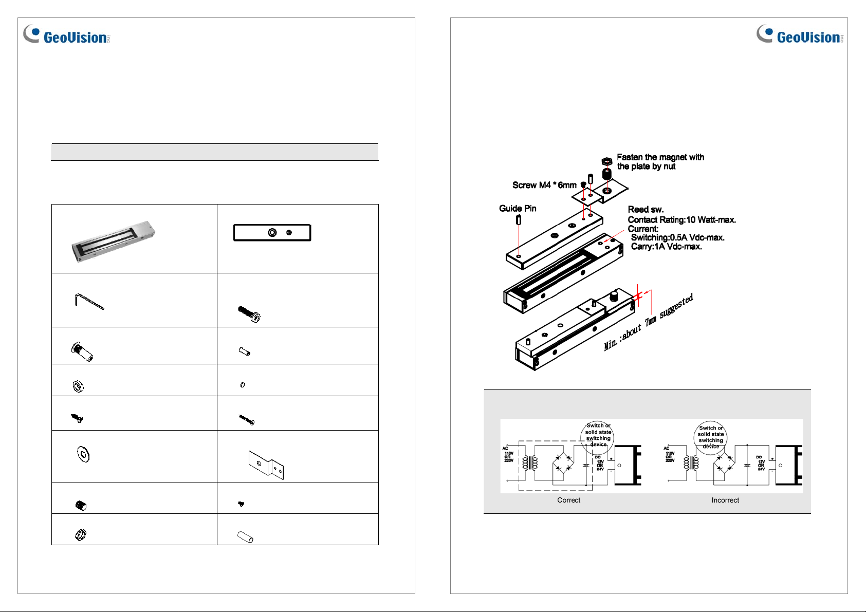
Packing List
1. MLSH01-0 electromagnetic lock x 1
3. Inner hexagon wrench x 1
5. Hat nut x 1
7. Black rubber spacer x 2
9. #10 (5/8”) screw x 2
2. Magnet faceplate x 1
4. M8 (35mm) screw + black rubber
spacer x 1
6. Galvanized steel rivet x 2
8. Aluminum shim x 2
10. #10 (1.25”) screw x 8
Installation
Before installing, add the thread lockers to all screws. Firmly tighten the screws to avoid
fastening loosen.
1. Install the electromagnetic lock to the doorframe.
Note: If the power switch is not wired between the DC source voltage and the magnet, it
will take longer to de-energize the magnet simulating residual magnetism.
11. Washer x 2
13. CU1201 screw + permanent magnet x 1
15. Inner hexagon nut x 1
May 13, 2011
12. Stainless steel bracket x 1
14. M4 (6mm) screw x 1
16. Aluminum tube x 1
1
2
May 13, 2011
Page 2
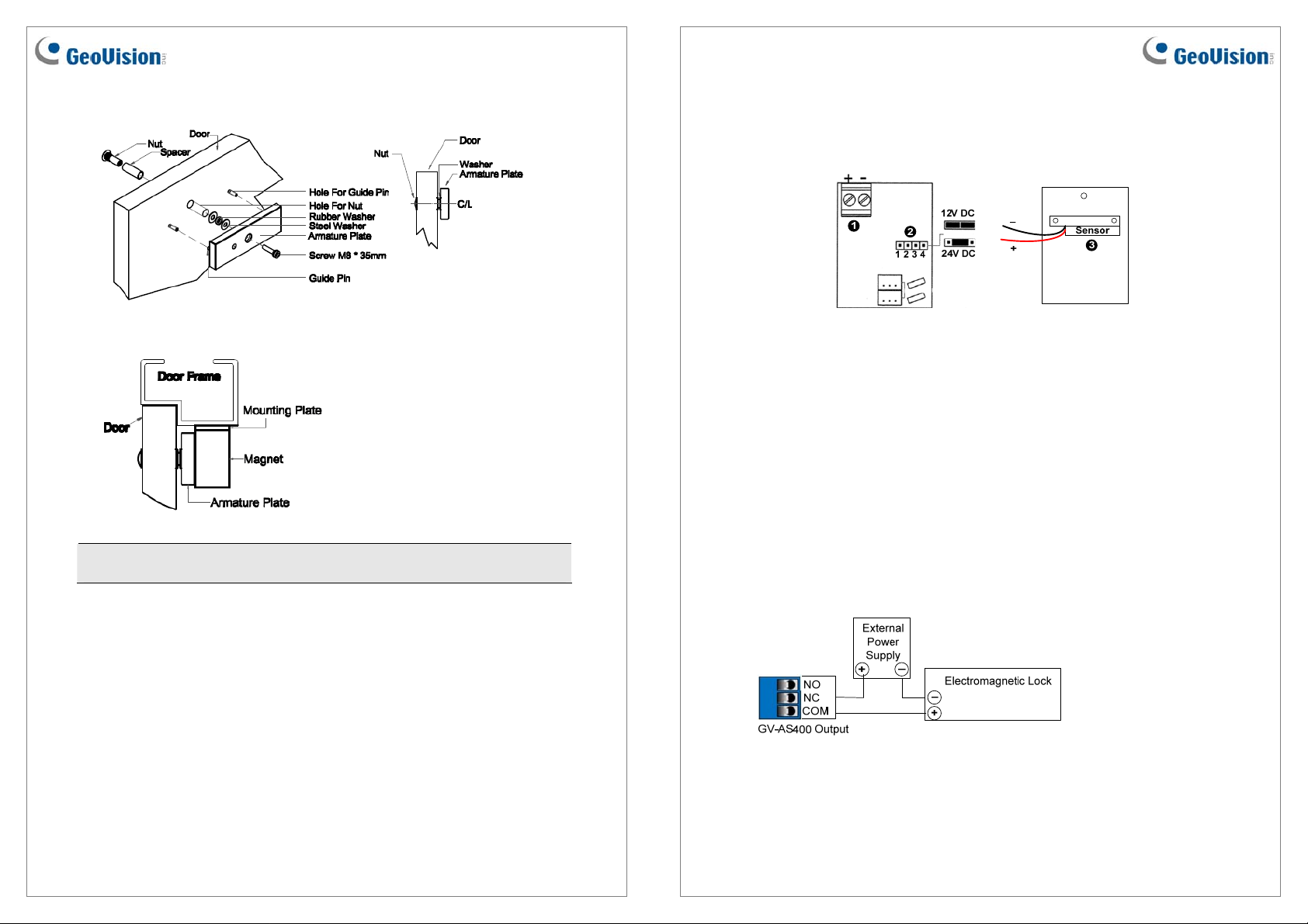
2. Mounts the armature plate to the door.
Contacts
Unscrew the cover of electromagnetic lock and you will see the diagram as below:
Typical Installation of the electromagnetic lock:
Note: To make the armature plate adjust its proper position to the magnet automatically,
do not fix the armature plate too tightly and make the rubber washer more flexible.
1. Power Terminal Block: Connects to the DC 12V / 24V power source.
2. Power Switch Jumper: Plug the power jumpers to Pins 1, 2 and Pins 3, 4 for a 12V
DC power source. Plug the power jumper to Pins 2, 3 for a 24V DC power source.
3. Sensor: Connects to the access control system by using the black and red wires. For
details, see Connecting Sensor to the Access Control System later in this installation
guide.
Connecting to the GV-AS Controller
To connect the electromagnetic lock to the GV-AS Controller, follow the steps below. Here
we use the GV-AS400 Controller for example.
1. To connect the power between the electromagnetic lock and the GV-AS400, refer to the
diagram as below.
Connect the (+) point on the electromagnetic lock to COM on GV-AS400, connect the
two (-) points of the electromagnetic lock and the external power supply together, and
connect the (+) point on the external power supply to NC on GV-AS400.
May 13, 2011
3
4
May 13, 2011
Page 3

2. To connect the sensor to the GV-AS400, connect the Red wire of the sensor to the Input
of the GV-AS400, and connect the Black wire of the sensor to the Ground of the GVAS400.
Specifications
Voltage DC 12V / 24V
3. On the Web interface of the GV-AS400, select Input Setting, and select an input type
and input function for the connected sensor from the electromagnetic lock.
4. On the Web interface of the GV-AS400, select Output Setting, and select an output type
and output function for the connected electromagnetic lock.
Input Type Input Function
Current
Holding Force
Dimension (L x W x H)
Armature Plate Dimension
(L x W x H)
Certification
500mA at 12V / 250mA at 24V
272.15 kg / 600 lb
250 x 47.2 x 26.6 mm / 9.84 x 1.86 x 1.05 in
185 x 38 x 12.5 mm / 7.28 x 1.50 x 0.49 in
CE and UL
For details on configuring the input and out devices, see 3.4.3.D Input Function and 3.4.3.E
Output Function on the GV-AS Controller User’s Manual.
May 13, 2011
5
6
May 13, 2011
 Loading...