

Page 1
ML200SLD Electric Bolt
The ML200SLD is an electric bolt, featured with a stainless steel faceplate and a built-in
voltage spike suppressor. It supports lock sensor and door status sensor functions. The failsafe electric bolt locks the door when the power is applied, and unlocks the door when the
power is removed. It can be applied to single-leaf or double-leaf doors.
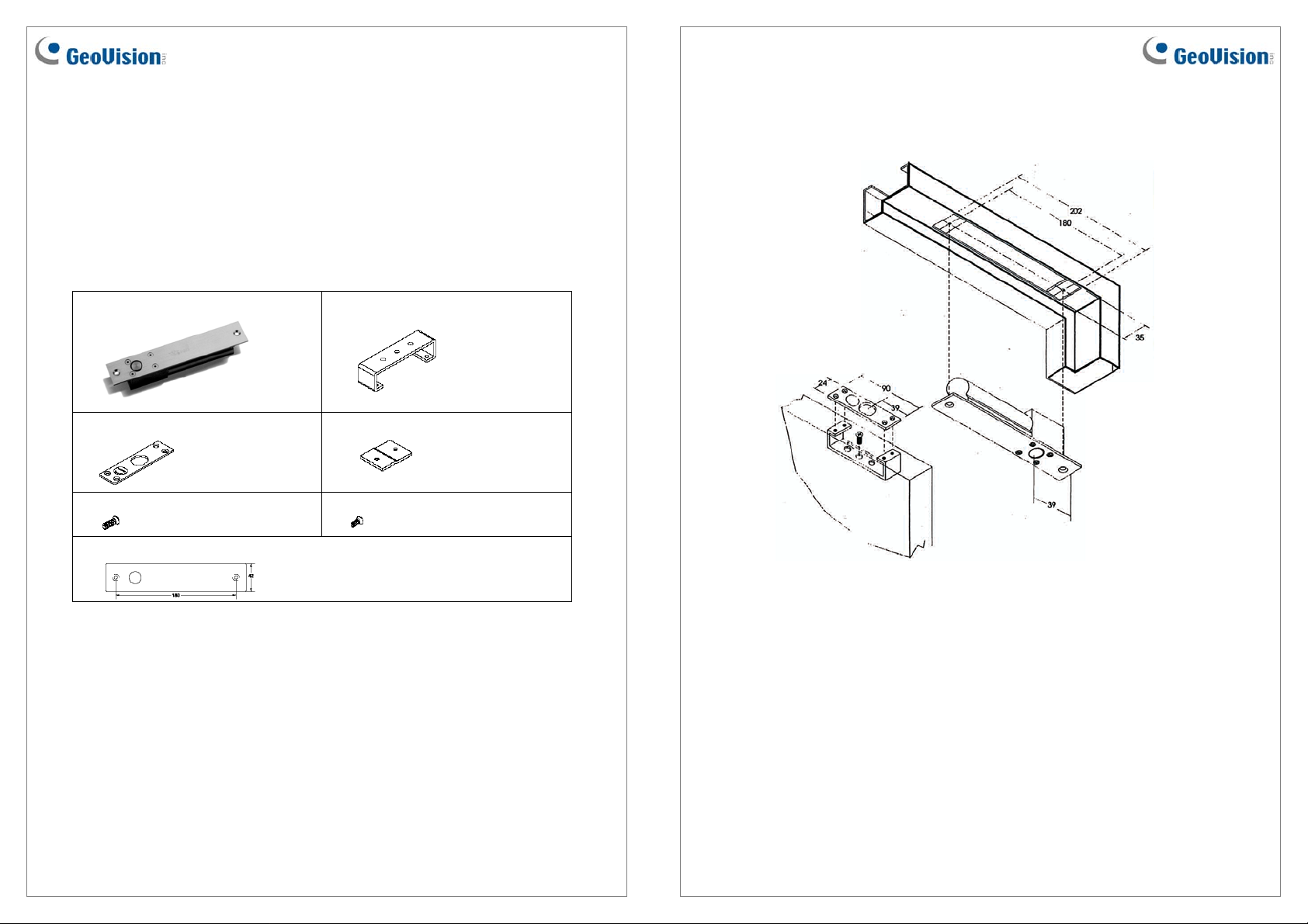
Packing List
1. ML200SLD electric bolt x 1
3. Base plate x 1
5. M5 (15 mm ) x 5
7. Cover plate x 1
2. Base bracket x 1
4. Extension plate x 2
6. M4 (11 mm ) x 8
Installation
Refer to the following diagram to install the electric bolt:
May 13, 2011
1
2
May 13, 2011
Page 2
Auto-lock Time Delay Setting
Use Jumper inserted on the electric bolt to set a lock-delayed time, after which the door will
automatically be locked. There are 3 options: 0, 2.5 and 5 seconds.
Wiring Instruction
Wire Definition
Connecting to the GV-AS Controller
To connect the electric bolt to the GV-AS Controller, follow the steps below. Here we use the
GV-AS400 Controller for example.
1. To connect the power between the electric bolt and the GV-AS400, refer to the diagram
as below.
External
Power
Supply
_
+
NO
NC
COM
GV-AS400 Output
Connect the Red wire of the electric bolt to COM on GV-AS400, connect the Black wire
of the electric bolt to the (-) point on the external power supply, and connect the (+) point
on the external power supply to NC on GV-AS400.
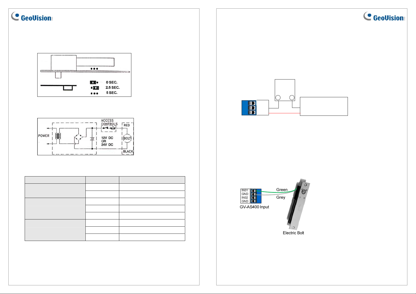
2. To connect the sensor to the GV-AS400, connect the Green wire of the sensor to the
Input of the GV-AS400, and connect the Grey wire of the sensor to the Ground of the
GV-AS400.
Electric Bolt
Black Wire
Red Wire
Electric Bolt
Lock Status Sensor
Door Status Sensor
May 13, 2011
Wire Definition
Red Positive (+)
Black Ground (-)
Blue NO
White COM
Yellow NC
Green NO
Grey COM
Orange NC
3
4
May 13, 2011
Page 3

3. On the Web interface of the GV-AS400, select Input Setting, and select an input type
and input function for the connected sensor from the electric bolt.
Specifications
Voltage
DC 12V or AC 24V
Input Type Input Function
4. On the Web interface of the GV-AS400, select Output Setting, and select an output type
and output function for the connected electric bolt.
For details on configuring the input and out devices, see 3.4.3.D Input Function and 3.4.3.E
Output Function on the GV-AS Controller User’s Manual.
Current
Lock Sensor Switch Rating
Door Status Sensor Switch Rating
Auto Relock Jumper
Dimension (L x W x H)
Weight
Certification
0.9A (start); 0.3A (standby)
1A at AC/DC 30V
0.5A at AC/DC 30V (magnetic reed switch)
0, 2.5 and 5 seconds (adjustable)
202 x 35 x 43 mm / 7.95 x 1.38 x 1.69 in
0.9 kg / 1.98 lb
CE and UL
May 13, 2011
5
6
May 13, 2011
 Loading...