

Page 1
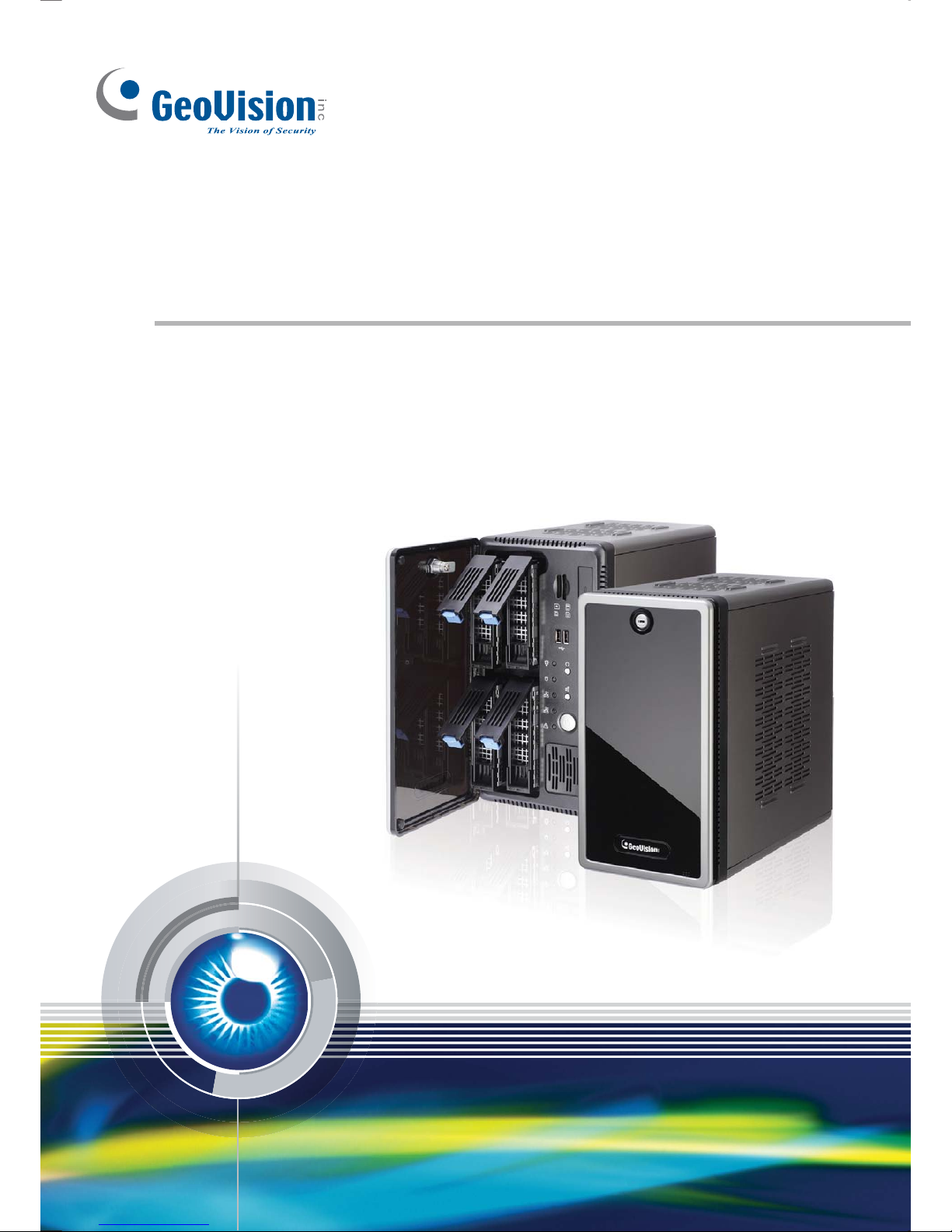
GV-Tower DVR/NVR System
TOWER-UM-B
User’s ManualUser’s Manual
Page 2
© 2014 GeoVision, Inc. All rights reserved.
Under the copyright laws, this manual may not be copied, in whole or in part,
without the written consent of GeoVision.
Every effort has been made to ensure that the information in this manual is
accurate. GeoVision, Inc. makes no expressed or implied warranty of any kind
and assumes no responsibility for errors or omissions. No liability is assumed
for incidental or consequential damages arising from the use of the information
or products contained herein.
GeoVision, Inc.
9F, No. 246, Sec. 1, Neihu Rd.,
Neihu District, Taipei, Taiwan
Tel: +886-2-8797-8377
Fax: +886-2-8797-8335
http://www.geovision.com.tw
Trademarks used in this manual: GeoVision, the GeoVision logo and GV
series products are trademarks of GeoVision, Inc. Windows and Windows XP
are registered trademarks of Microsoft Corporation.
January 2014
Page 3

Welcome to the GV-Tower DVR/NVR System User’s Manual.
The Manual provides an overview of the GV-Tower DVR/NVR System and its
accessories. It also includes the instructions to guide you through the installation and
use of the GV-Tower DVR/NVR System:
• Chapter 1, Introduction
Identifies the GV-Tower DVR/NVR System’s accessories and options.
• Chapter 2, Overview
Identifies the GV-Tower DVR/NVR System’s components.
• Chapter 3, Getting Started
Provides step-by-step instructions on setting up the GV-Tower DVR/NVR System.
• Chapter 4, NVR Health Analysis
Introduces how to collect data to obtain the service of DVR/NVR health analysis
from GeoVision.
• Chapter 5, Troubleshooting
Suggests courses of action if the GV-Tower DVR/NVR System doesn’t seem to be
working properly.
User’s Manual for
GV-Tower DVR/NVR System
Page 4

Contents
Safety Instructions ...................................................................................................iv
Chapter 1 Introduction........................................................................................... 1
1.1 Features .................................................................................................................1
1.2 Model .................................................................................................................... 2
1.3 Software License ...................................................................................................3
1.4 Packing List ............................................................................................................4
1.5 Options...................................................................................................................5
Chapter 2 Overview ............................................................................................... 6
2.1 Front View...............................................................................................................6
2.2 Rear View...............................................................................................................7
Chapter 3 Getting Started...................................................................................... 8
3.1 Basic Installation..................................................................................................... 8
3.1.1 Using IR Remote Control...........................................................................10
3.1.2 Connecting to 2 Monitors...........................................................................11
3.2 Installing the Hard Drive........................................................................................ 12
3.3 Formatting the Hard Drive..................................................................................... 14
3.4 Adding the Hard Drive to the Recording Path........................................................19
3.5 Setting Up On-Screen LED Panel.........................................................................21
3.6 Replacing the Hard Drive ......................................................................................24
3.7 Configuring the IP Address ................................................................................... 24
3.8 Exiting to Windows................................................................................................28
3.9 Returning to GV-Desktop ...................................................................................... 29
3.10 Twin View Display...............................................................................................30
3.11 Digital Matrix ....................................................................................................... 32
3.11.1 Activating Multiple Monitors ...................................................................32
3.11.2 Setting Live View ...................................................................................33
3.11.3 Setting Scanned Pages .........................................................................34
3.11.4 Setting Pop-up Alert...............................................................................35
3.11.4.1 Setting Pop-up Positions.....................................................................36
3.11.5 Setting Live View with Pop-up Alert........................................................37
3.12 System Restoration............................................................................................. 38
3.12.1 Restoring System ..................................................................................38
3.12.2 Changing Video Standard after Recovery ..............................................40
3.13 Updating GV-Tower DVR/NVR System ............................................................... 41
Chapter 4 NVR Health Analysis .......................................................................... 42
ii
4.1 System Settings.................................................................................................... 42
Page 5

4.2 System Log...........................................................................................................44
4.3 Information of Your Computer System...................................................................45
4.4 Health Analysis Form ............................................................................................47
4.5 Check List.............................................................................................................47
Chapter 5 Troubleshooting ................................................................................. 48
Specifications ......................................................................................................... 55
Appendix….............................................................................................................. 55
A Hard Disk Requirements.......................................................................................... 55
B Total Frame Rate Supported....................................................................................56
C Supported IP Devices..............................................................................................57
Warranty Policy....................................................................................................... 58
Warranty Requirements ......................................................................................... 61
Warranty Form ........................................................................................................ 63
iii
Page 6

iv
Safety Instructions
Observe these safety instructions to help ensure against injury to yourself and damage
to the product.
z
Read all safety and installation instructions before you operate the product.
z Do not operate the product in high humidity areas or expose it to water or moisture.
z Do not put the product in an unstable, a slanting or vibrated place.
z Do not block any ventilation opening.
z Do not install the product near any heat sources such as radiator, heat register or
other apparatus that produce heat.
z Operate the product using only the type of power source indicated on the marking label.
z Do not defeat the safety purpose of the grounding-type plug. A grounding plug has two
blades and a third grounding prong. The third prong is provided for your safety. If the
provided plug does not fit into your outlet, consult an electrician for replacement of the
obsolete outlet.
z Do not overload wall outlets or extension cords, as this may cause fire or electric
shock.
z Do not use the product when abnormality occurs, such as emitting smoke from the
product, smelling burning, being damaged by drop, invasion of foreign objects inside the
product, etc. Be always sure to remove the AC adaptor at once and contact your dealer.
z Do not use accessories or attachments not recommended by the manufacturer, as they
may cause hazards and void the warranty.
z Do not attempt to service the product yourself, as removing the casing may expose
you to dangerous voltage and void the warranty.
Page 7

Introduction
1
Chapter 1 Introduction
1.1 Features
‧ Powered by Intel Core i3 or i5 Processor
‧ 64-bit Windows Embedded Standard 7
‧ Support for GPU Decoding
‧ 4-bay hot swap data HDD
‧ Maximum storage capacity of up to 12 terabytes
‧ Pre-installed recovery from the hidden partition
‧ Dual Gigabit LAN ports
‧ Dual monitor display (VGA and HDMI outputs)
‧ Support for 3
rd
party IP cameras with H.264
‧ Support for 32-channel GV-Hybrid DVR (16-channel hardware compression plus
16-channel digital video recorder)
‧ All-in-one solution (Live View, Playback, Recording, Backup, CMS)
‧ Video analysis (Advanced Motion Detection, Privacy Mask, Scene Change Detection
and Counter)
‧ Fisheye camera dewarping function
‧ Automatic connection to GV IP cameras
‧ H.264 / MJPEG / MPEG4
‧ Dual video streams
‧ On-screen LED panel for HDD status
‧ Smart device access
‧ Multiple (29) languages
1
Page 8
1.2 Model
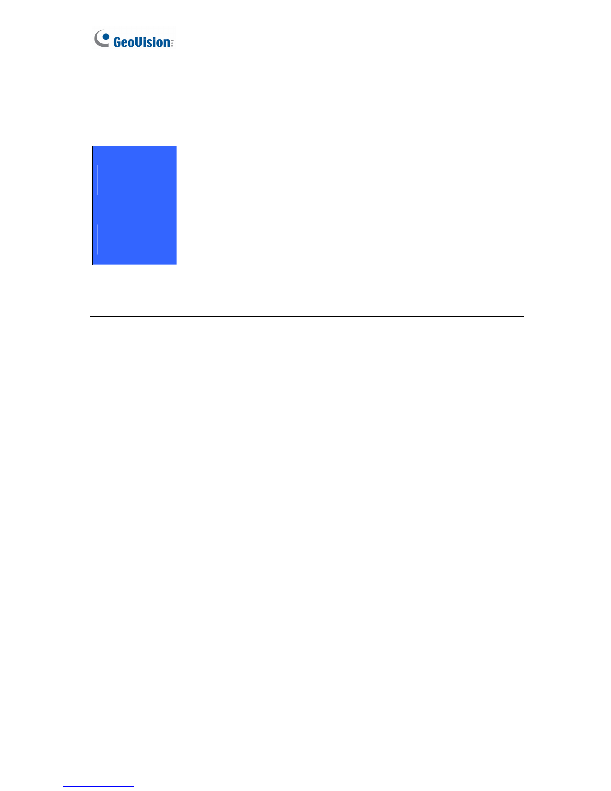
The GV-Tower DVR/NVR System has the following models:
GV-Tower DVR
System
- 16-channel hardware compression plus 16-channel digital video
recorder
- 16-channel hardware compression: Records up to 480 (NTSC) / 400
(PAL) fps at D1 resolution
GV-Tower NVR
System
- 32-channel digital video recorder
- 32-channel of free GeoVision IP devices, or 32-channel combination of
GeoVision IP devices and third-party IP devices digital video recorder
2
Note: For third-party IP device connection, it is required to additionally purchase an internal
GV-NVR Dongle.
Page 9
Introduction
1
1.3 Software License
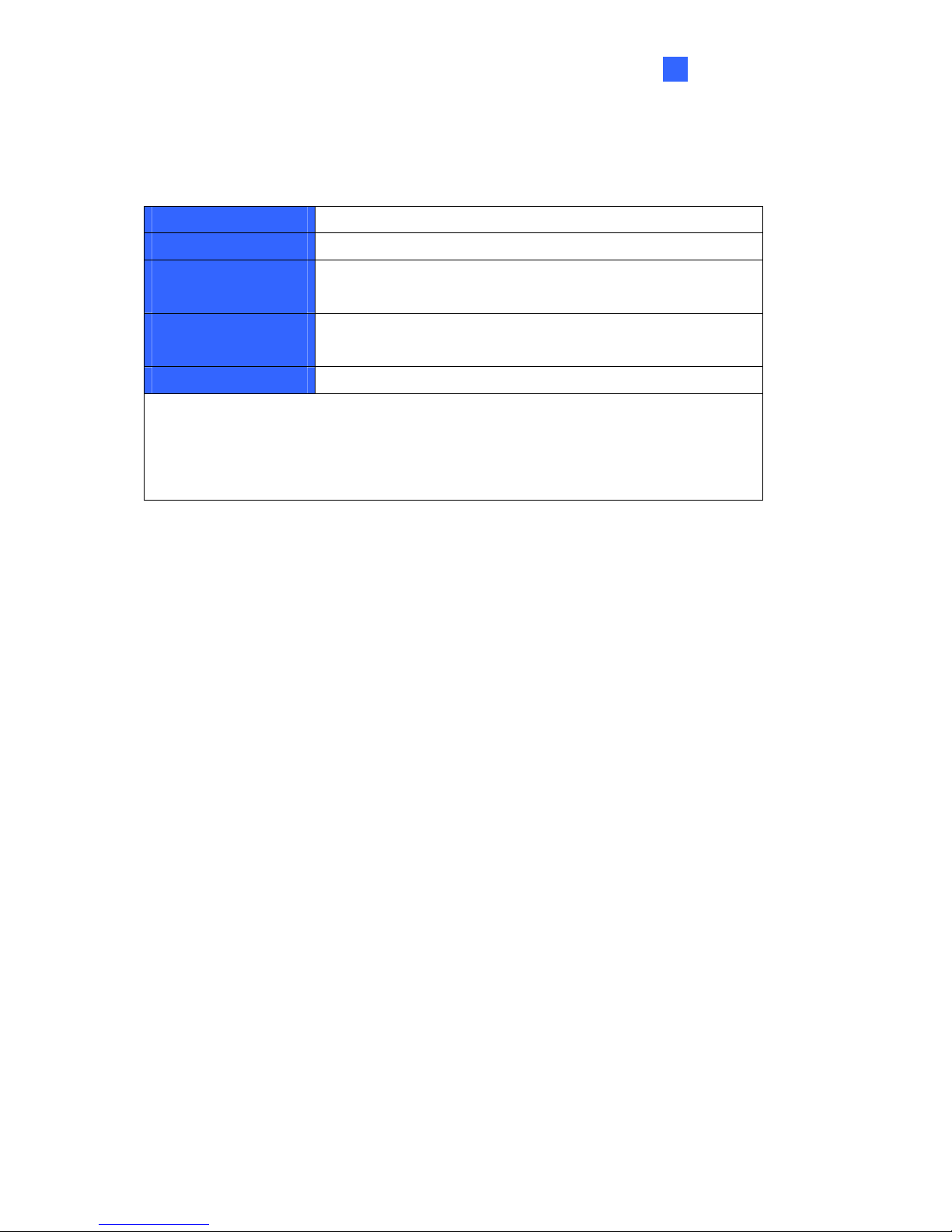
3
Free License
32 channels from GV-IP devices
Maximum License
32 channels from third-party IP devices
Increment for Each
License
1 to 32 third-party IP cameras at an increment of 2
Optional
Combinations
N/A
Dongle Type
Internal or External
Note:
1. The Maximum License is a paid service.
2. It is recommended to use the internal GV-USB Dongle to have the Hardware
Watchdog function which restarts the PC when Windows crashes or freezes
Page 10
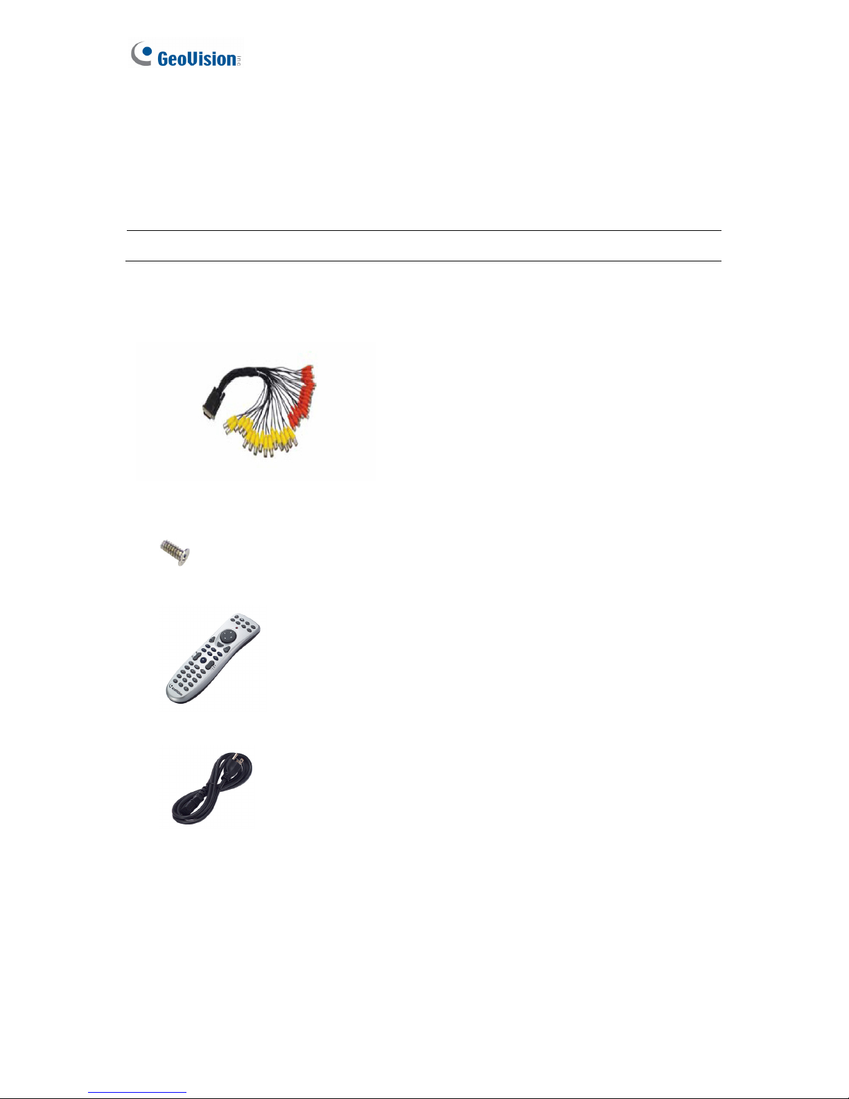
1.4 Packing List
The GV-Tower DVR/NVR System package includes the following items. If any of the items are
missing or damaged, contact your dealer to arrange a replacement.
Important: Please keep the original carton and all packing materials for future shipping need.
1. GV-Tower DVR/NVR System x 1
2. LFH Audio and Video Cable x 1 (only for GV-Tower DVR System)
3. Keys for Dard Disk Safety Lock x 2
4. Hard Disk Drive Screw x 16
5. GV-IR Remote Control x 1
6. AC Power Cord x 1
7. GV-Tower DVR/NVR System Quick Start Guide x 1
4
8. Software DVD x 1
Page 11
Introduction
5
1
1.5 Options
Optional devices can expand your GV-Tower DVR/NVR System’s capabilities and versatility.
Contact your dealer for more information.
GV-Data Capture V3
Box
GV-Data Capture V3 Box can integrate the GV-Tower DVR/NVR
System to an electronic POS system, while GV-Data Capture V3E
Box can establish such integration through LAN or Internet.
GV-Hub V2
An easy way for serial port extension. This hub can add 4
RS-232/RS-485 serial ports through the GV-Tower DVR/NVR’s USB
port.
GV-COM V2
This unit can add 1 RS-232/RS-485 serial port through the
GV-Tower DVR/NVR System’s USB port.
GV-IO Box (4 Ports)
GV-IO Box 4 provides 4 inputs and 4 relay outputs, and supports
both DC and AC output voltages. A USB port is also provided for PC
connection.
GV-IO Box (8 Ports)
GV-IO Box 8 provides 8 inputs and 8 relay outputs, and supports
both DC and AC output voltages. A USB port is also provided for PC
connection.
GV-IO Box (16 Ports)
GV-IO Box 16 provides 16 inputs and 16 relay outputs, and supports
both DC and AC output voltages. A USB port is also provided for PC
connection.
GV-Joystick
GV-Joystick facilitates the PTZ camera control. It can be either
plugged into the GV-Tower DVR/NVR System for independent use
or connected to GV-Keyboard to empower the operation. However,
this device can only work on GV-System version 8.2 or later.
GV-Keyboard V3
The GV-Keyboard V3 is designed to program and operate the
system, and it can also be connected with PTZ cameras directly for
PTZ control.
Page 12
Chapter 2 Overview
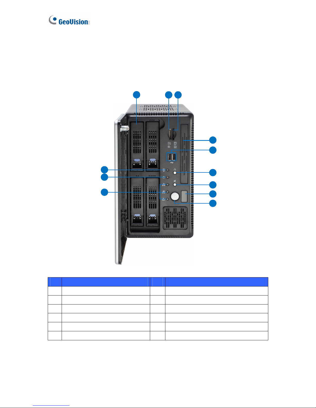
2.1 Front View
32
1
4
5
6
7
8
9
12
11
10
Figure 2-1
No. Name No. Name
1 HDD x 4 7 Not Functional
2 Not Functional 8 IR Receiver
3 Not Functional 9 Power Button
4 Not Functional 10 Not Functional
5 Not Functional 11 HDD Activity LED (Red)
6 Reset Button 12 Power LED (Blue)
6
Page 13
Overview
7
2
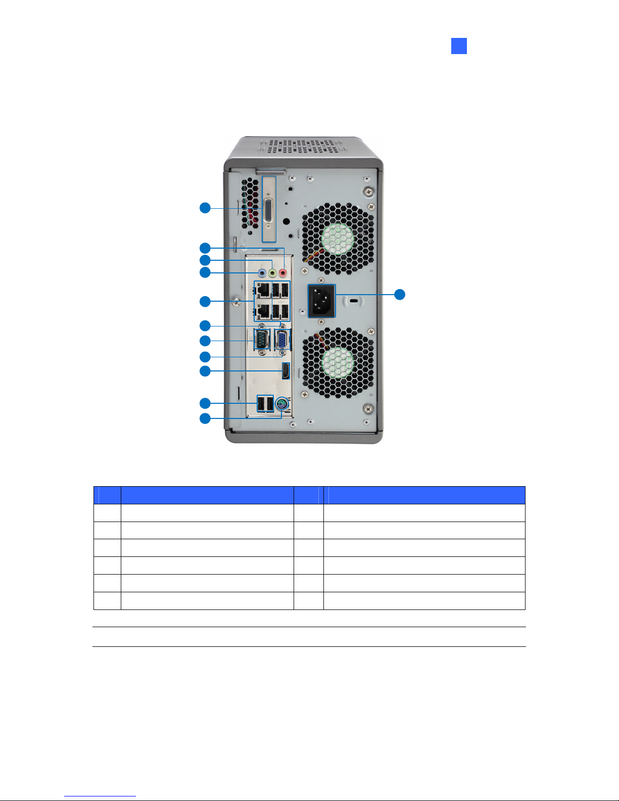
2.2 Rear View
10
1
2
3
4
5
6
7
8
9
11
12
Figure 2-2
No. Name No. Name
1 Power Connector 7 USB 2.0 Port x 4
2
LFH Audio and Video Connector*
8 Not Functional
3 Audio Microphone In Port 9 VGA Monitor Output
4 Audio Line Out Port 10 HDMI Port
5 Audio Line In Port 11 USB 2.0 Port x 2
6 Ethernet Port x 2 12 PS/2 Port (only for the keyboard)
Note: The feature marked with * is for GV-Tower DVR System only.
Page 14
Chapter 3 Getting Started
3.1 Basic Installation
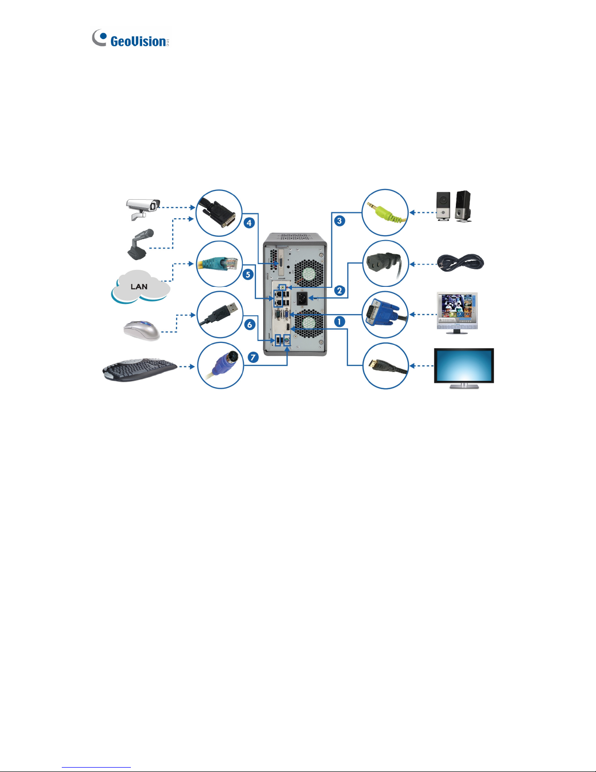
This section describes all the equipments required to program and operate the GV-Tower
DVR/NVR System. Here we use GV-Tower DVR System as the example.
Figure 3-1
1. There are two ways to connect the monitor to the GV-Tower DVR/NVR System.
• Using the VGA cable supplied by the monitor manufacturer, connect the VGA
monitor.
• Using the HDMI cable supplied by the HDTV manufacturer, connect the HDTV.
2. Using the supplied power cord, connect one end to the AC input and the other end to the
power outlet.
3. Connect speakers to the Audio Line Out port.
4. Using the supplied LFH Audio and Video cable, connect the yellow ends to the cameras,
and the red ends to the microphones.
5. Using the RJ-45 cable, connect one end to the Ethernet port and the other end to Network.
6. Connect the mouse to the USB port.
7. Connect the keyboard to the PS/2 port.
8
Page 15

Getting Started
3
Once the above hardware is properly connected, press the Power button on the front panel to
start the system. It takes about 1 minute for startup. The system should load automatically and
display cameras in the main screen.
9
Page 16
3.1.1 Using the IR Remote Control
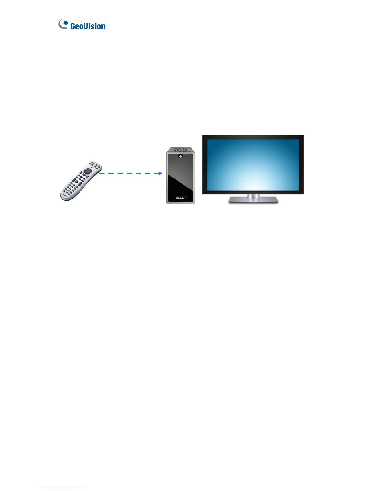
The GV-IR Remote Control provides easy control of the GV-Tower DVR/NVR System. Its
receiver is a built-in device.
For details, see GV-IR Remote Control User’s Manual (GV-Desktop < Program button < User
Manual).
Figure 3-2
10
Page 17
Getting Started
3
3.1.2 Connecting to 2 Monitors
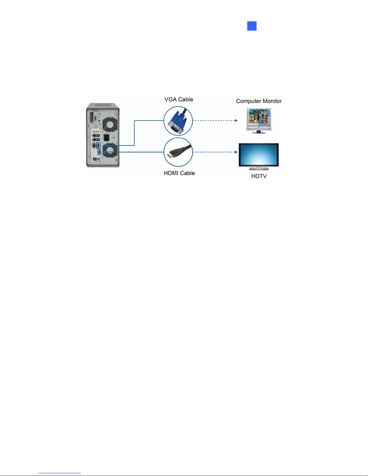
You can connect the 2 monitors to the ports labeled below on the back panel of the GV-Tower
DVR/NVR System. Here we use GV-Tower DVR as the example.
Figure 3-3
11
To install other required equipment, follow the steps in 3.1 Basic Installation.
Page 18
3.2 Installing the Hard Drive
The GV-Tower DVR/NVR System uses SATA hard drives for video and audio data storage.
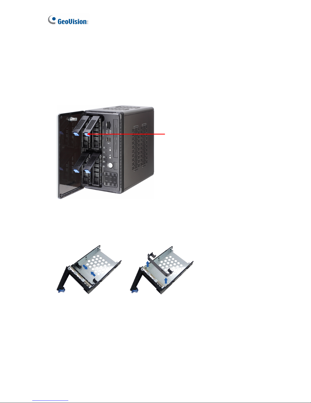
Before recording, ensure to install your hard drives. Follow the below steps to install the hard
drive.
1. Press the release latch. The drawer handle pops up.
Figure 3-4
2. Pull out the drive drawer.
3. Remove the plastic carrier from the chassis.
Figure 3-5
12
Release Latch
Page 19
Getting Started
3
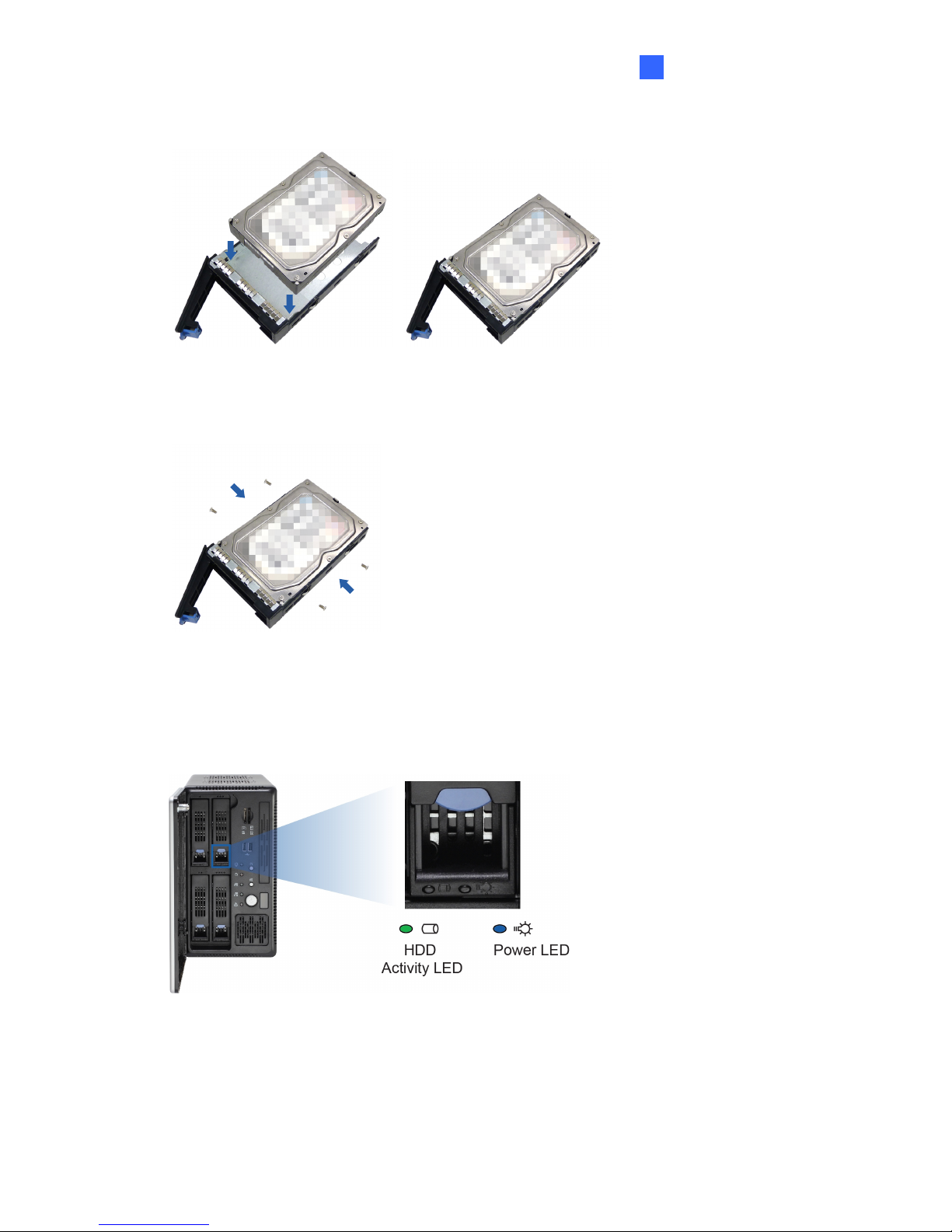
4. Insert the hard drive in the drawer.
Figure 3-6
5. Secure the hard drive with the 4 screws, and make sure all screw heads flush with the
surface.
Figure 3-7
6. Put the drawer back in the drive bay of the GV-Tower DVR/NVR System, and push the
latch until it locks.
13
7. When the Power LED on the drawer shines blue, the hard drive is now ready to use.
Figure 3-8
Page 20
3.3 Formatting the Hard Drive
After installing hard drives to your system, you will need to format them before use.
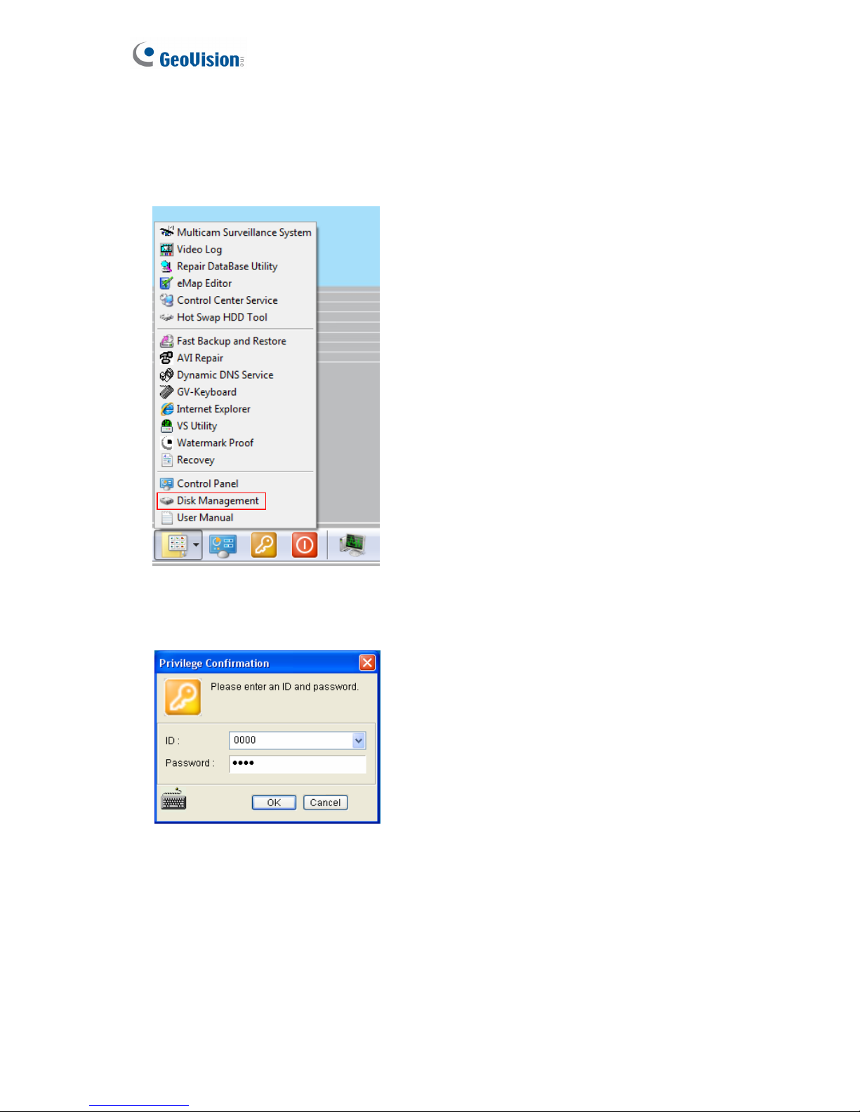
1. On the GV-Desktop, click the Programs button, and select Disk Management.
Figure 3-9
2. Type the ID and password in the dialog box. The default ID and password are “0000”.
Figure 3-10
14
Page 21
Getting Started
3
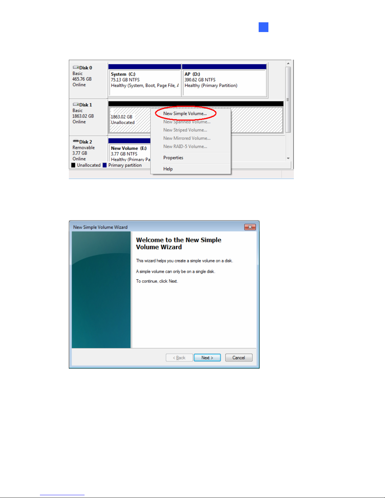
3. Right-click in the unallocated space of a new drive, and select New Simple Volume.
Figure 3-11
4. The New Simple Volume Wizard appears. Click Next to continue.
Figure 3-12
15
Page 22
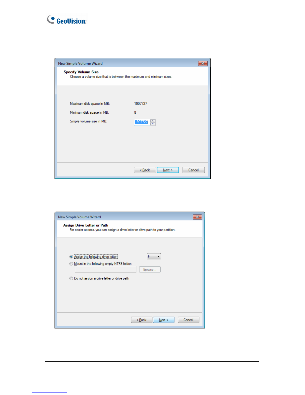
5. The default partition size is the same as the maximum disk space. Make changes if
necessary. Click Next to continue.
Figure 3-13
6. Assign a drive path that is not in use by other devices, and click Next to continue.
Figure 3-14
16
Note: The default drive path starts from D:\.
Page 23
Getting Started
3
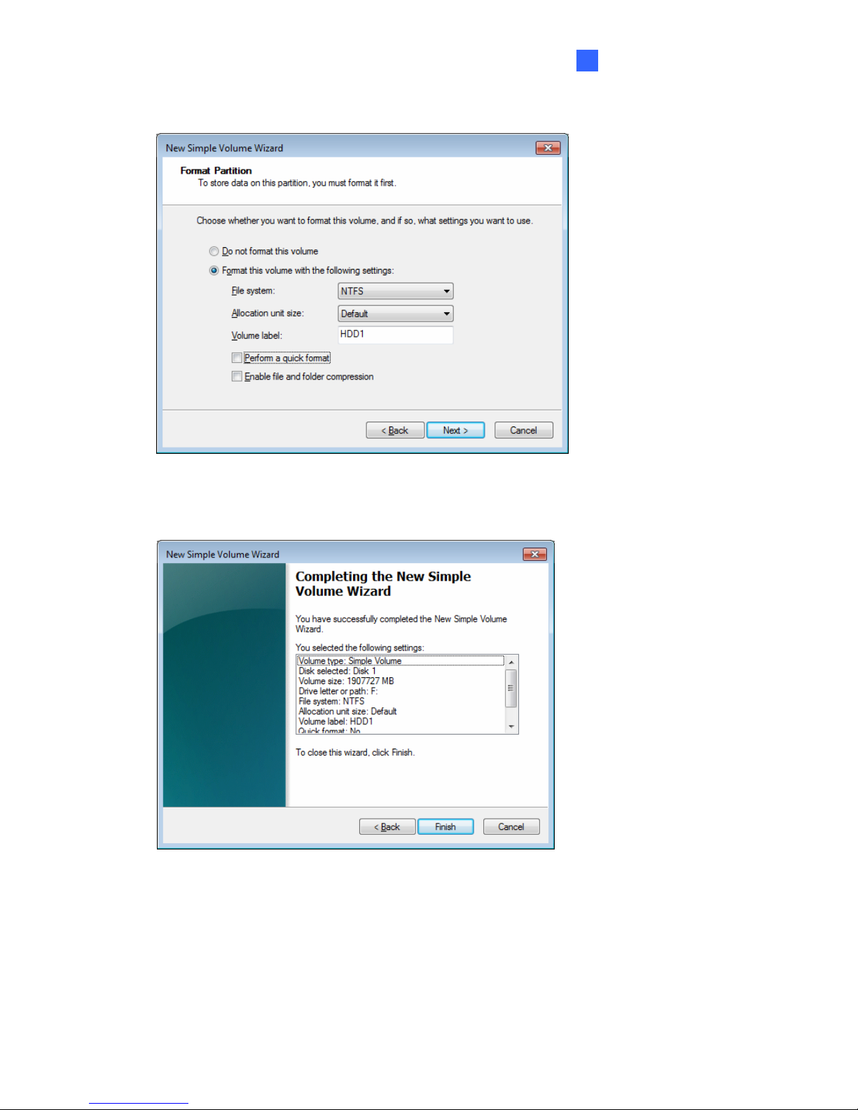
7. Type a name in the Volume label box, ex. HDD1, and click Next to continue.
Figure 3-15
8. When the formatting is complete, click Finish to close the wizard.
Figure 3-16
17
Page 24
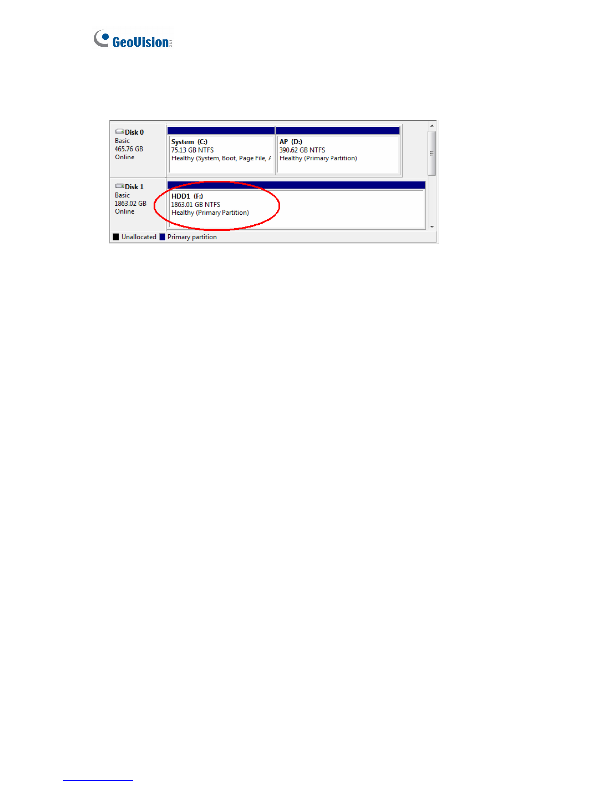
9. When the drive is successfully initialized, partitioned, and formatted, its status description
should display “Healthy.”
18
Figure 3-17
Page 25
Getting Started
3
3.4 Adding the Hard Drive to the Recording Path
For GV-Tower DVR/NVR System, you need to add the formatted hard drives to the recording
path before recording.
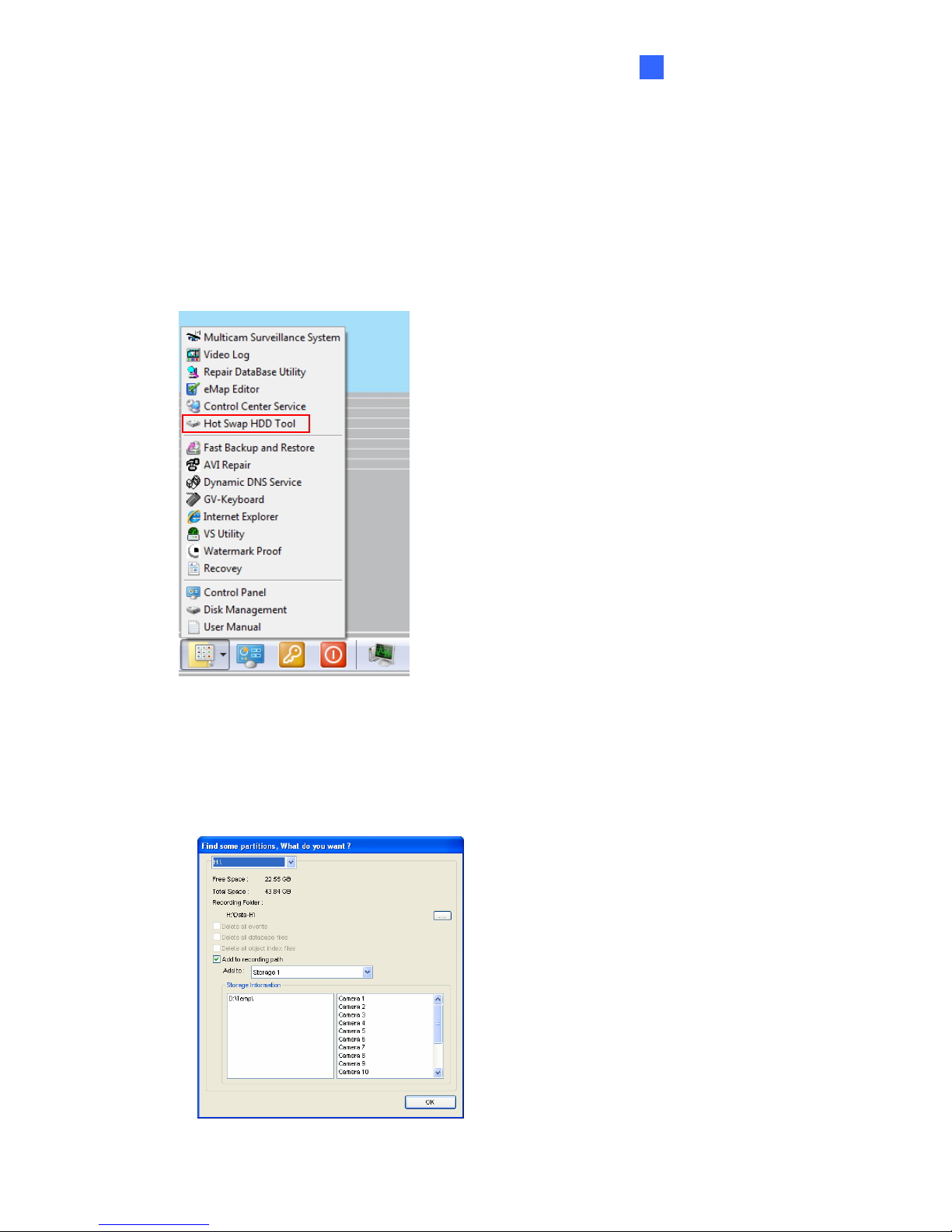
1. On the GV-Desktop, click the Programs button, and select Hot Swap HDD Tool. The
MediaMan Tools window appears.
Figure 3-18
2. If a hard drive is already inserted, right-click it in the MediaMan Tools window, select Add
for recording, and then select the storage group from the drop-down list.
3. If a hard drive is not inserted, follow these steps:
A. Insert a hard drive or plug a USB hard drive to the GV-Tower DVR/NVR System.
Figure 3-19
19
Page 26
B. Select Add to recording path, and select the storage group from the drop-down list.
Note: Storage 1 is the default storage group.
4. Click OK to automatically configure the hard drive to the recording path.
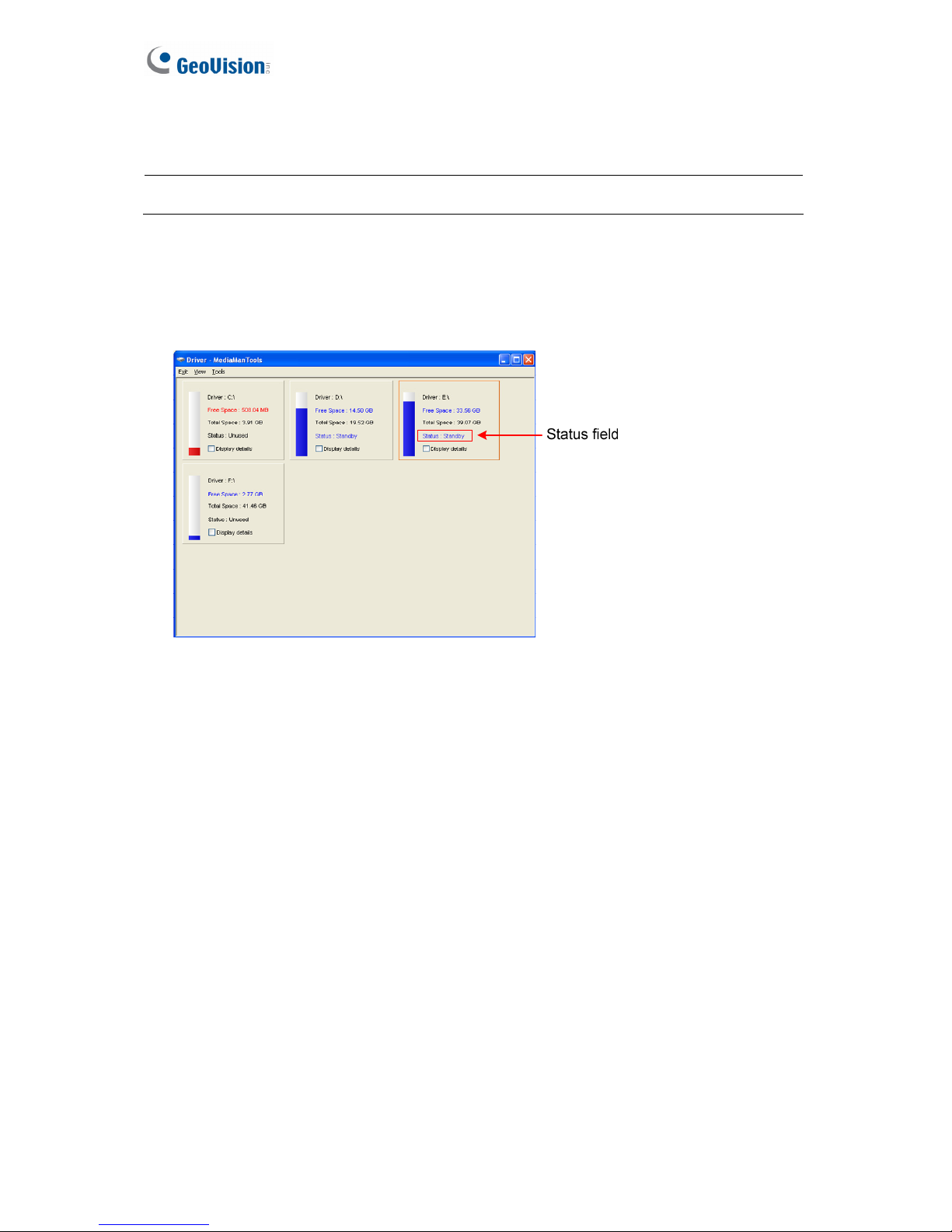
5. In the MediaMan Tools window, if the hard drive is successfully added to store data, its
Status field should display “Standby”.
Figure 3-20
6. To add another formatted hard drive for storage, repeat the above steps.
For the details on using Hot Swap HDD Tool, see Hot-Swap Recording, Chapter 11, DVR
User’s Manual (GV-Desktop < Program button < User Manual).
20
Page 27
Getting Started
3
3.5 Setting Up On-Screen LED Panel
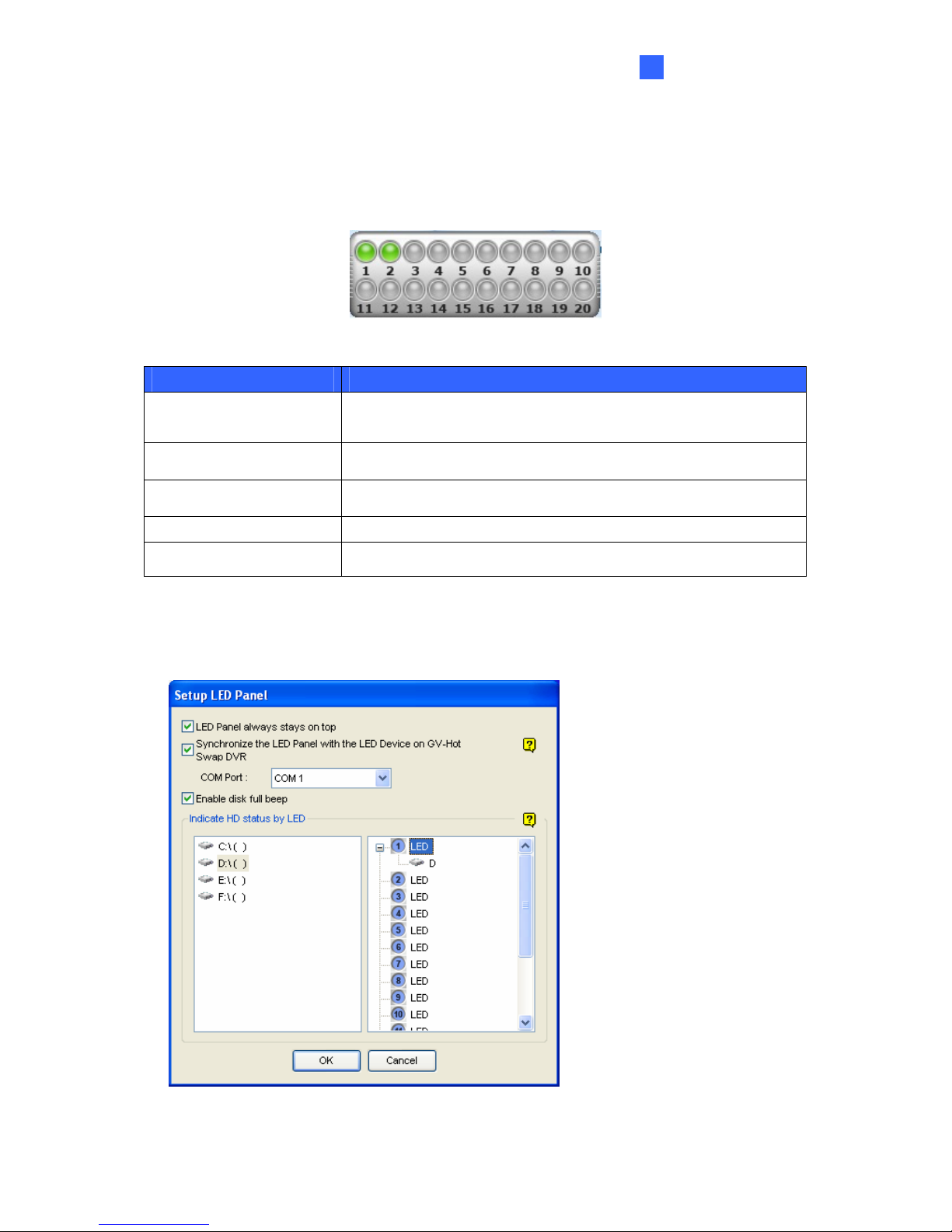
For GV-Tower DVR/NVR System, a LED panel on the screen provides a quick indication of
the activity status of hard disk drives.
Figure 3-21
LED Color Description
Gray
- No HDD is assigned to this LED.
- The system is not started.
Green A HDD is assigned to this LED.
Red The HDD is full.
Flashing Green The system is recording.
Flashing Red The HDD is recycling.
1. On the GV-Desktop, click the Programs button, and select Hot Swap HDD Tool.
21
2. Click Tools on the menu bar, and select Setup LED Panel. This dialog box appears.
Figure 3-22
Page 28

LED Panel always stays on top: This option makes the LED panel stay on top of
other windows when the Media Man Tools window is minimized.
Synchronize the LED Panel with the LED Device on GV-Tower DVR/NVR
System: Not functional.
Enable disk full beep: When the hard disk drive is full, the system sounds on. Note
this function only works when speakers are connected to the GV-Tower DVR/NVR
System.
3. By default, only the hard disk drive D will be assigned to LED. If you want to re-assign the
hard disk drive or assign other drives to LEDs, freely drag and drop the hard disk drive to
the desired LED on the tree.
4. Click OK to apply the settings, and minimize the MediaMan Tools window to display the
LED panel on the screen.
5. If you want to return to the MediaMan Tools window, right-click the LED panel and select
Switch to the setup window.
Note:
1. Because the LEDs are designed to indicate the video and audio files are being written
or read, it is not recommended to assign the HDDs that store log files to the LEDs.
2. If the HDD that stores log files is assigned to a LED and its LED turns red, make sure
the log files are not being written before you remove it. Otherwise, the log files might
be lost during the removal.
22
Page 29

Getting Started
3
3.6 Replacing the Hard Drive
You can replace the hard drive without shutting down the GV-Tower DVR/NVR System.
1. Do not turn off the power before you replace the hard drive.
2. Push the release latch. The drawer handle pops up.
3. Lift the handle, pull out the drawer slightly and wait until the hard drive spins down.
4. Pull out the drawer completely, remove the hard drive, and then mount a new one.
5. Put the drawer back in the drive bay.
23
6. Push the release latch until it locks.
Page 30
3.7 Configuring the IP Address
GV-Tower DVR/NVR System supports remote monitoring, control and configuration over a
network connection. The following default IP addresses will automatically be assigned.
• Connection 1: 192.168.0.200
• Connection 2: 192.168.0.201
• Default Subnet Mask: 255.255.252.0
To change the above default IP addresses, follow the steps below.
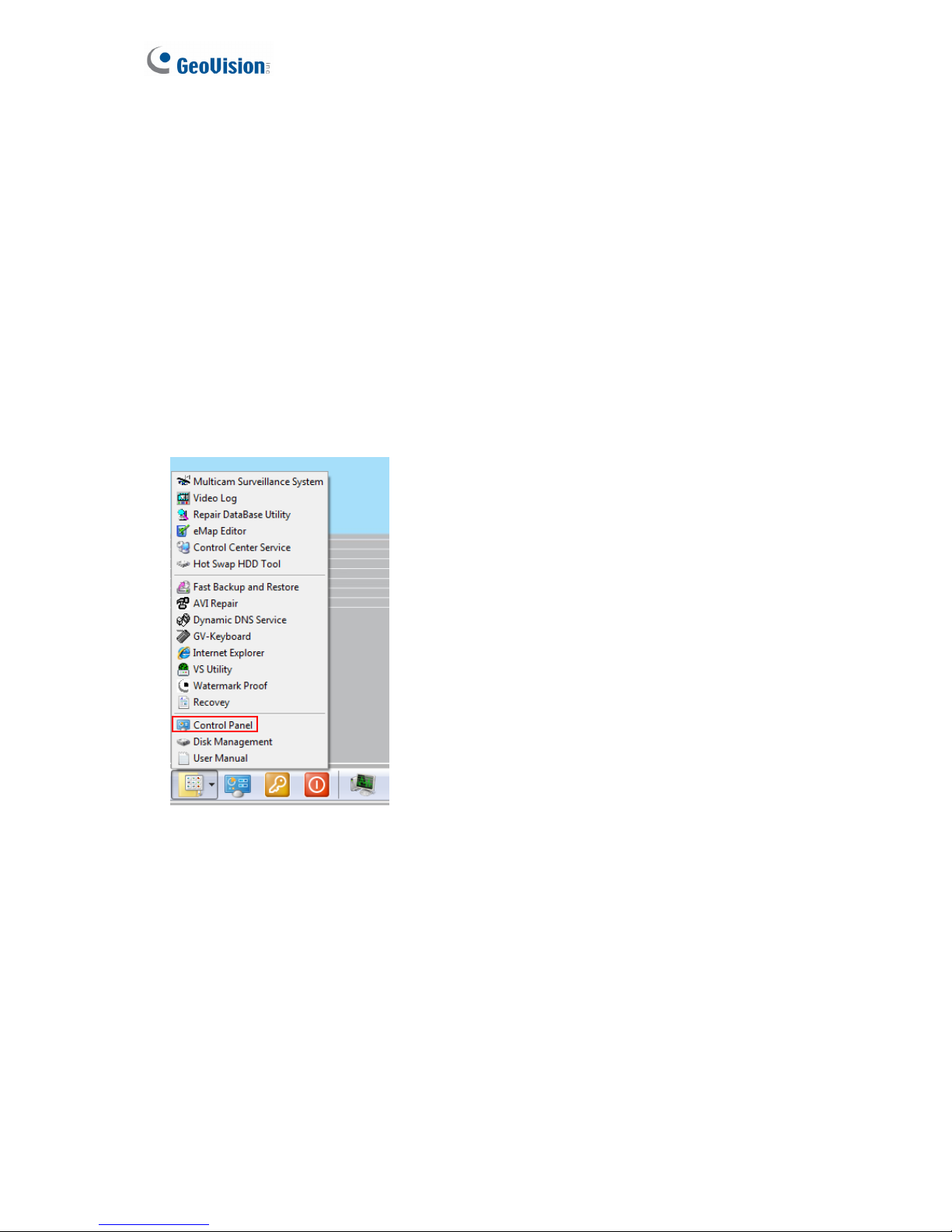
1. On the GV-Desktop, click the Programs button, and select Control Panel.
Figure 3-23
2. Type the ID and password. The default ID and password are “0000”. The Control Panel
window appears.
24
Page 31
Getting Started
3
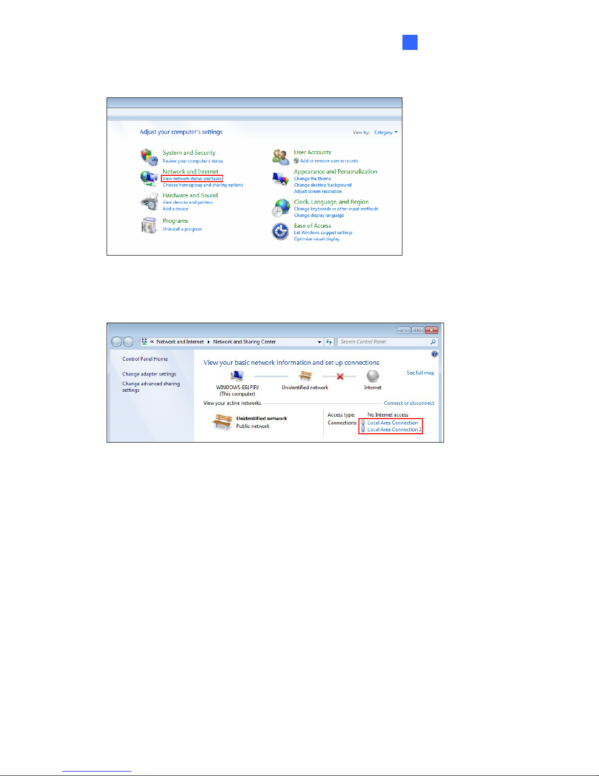
3. Under Network and Internet, click View network status and tasks.
Figure 3-24
4. Under Connections, select the Local Area Connection you want to configure.
Figure 3-25
25
Page 32
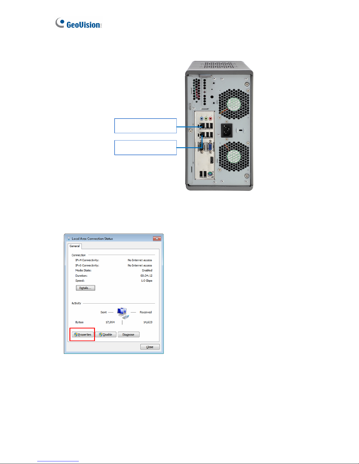
The local area connections listed correspond to the Ethernet ports as shown below:
Local Area Connection 1
Default IP: 192.168.0.200
Local Area Connection 2
Default IP: 192.168.0.201
Figure 3-26
26
5. Select Internet Protocol Version 4 (TCP/IPv4), and select Properties.
Figure 3-27
Page 33
Getting Started
3
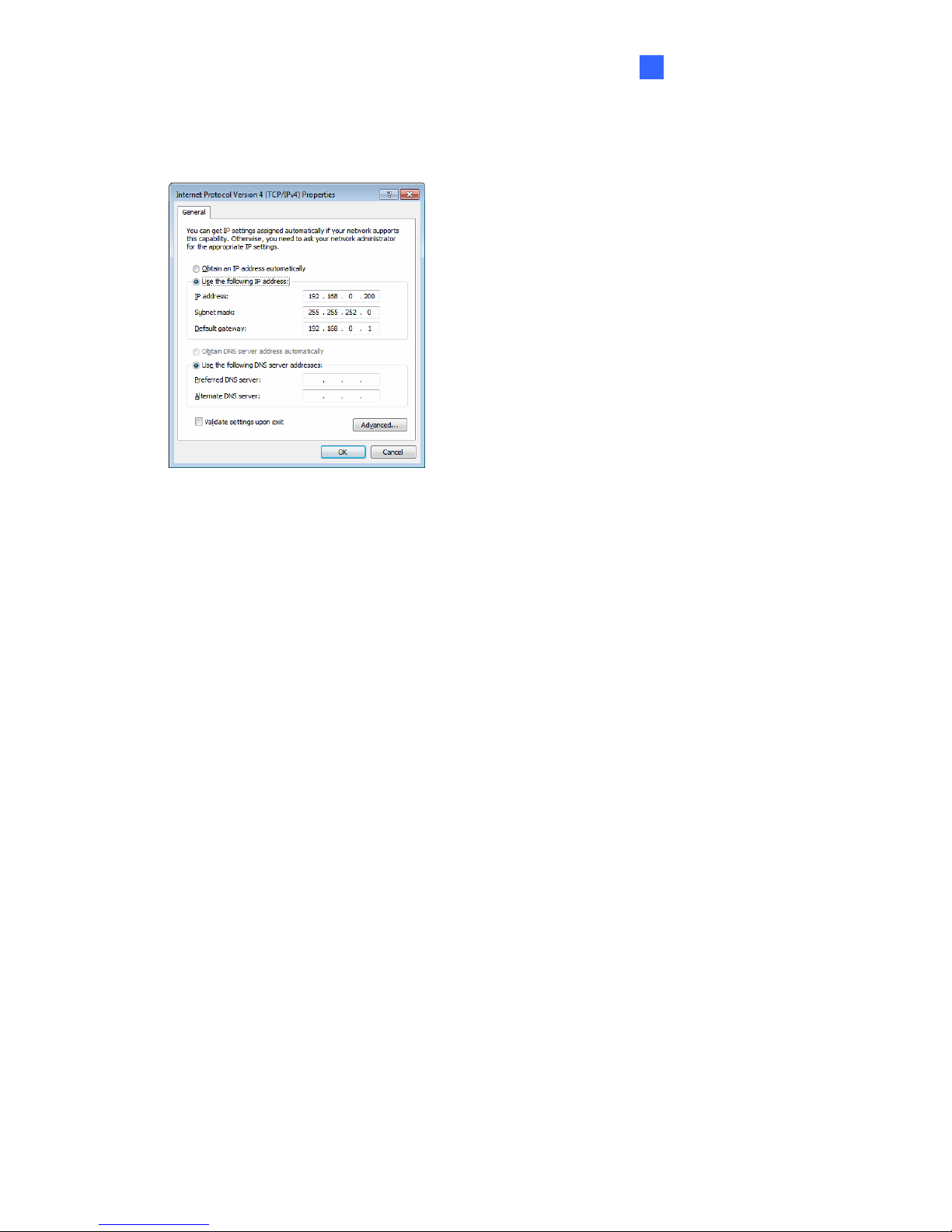
6. Select Use the following IP address and type the new IP information in the fields. Or
select Obtain an IP address automatically to enable dynamic IP address.
Figure 3-28
27
7. Click OK to finish the setting.
Page 34
3.8 Exiting to Windows
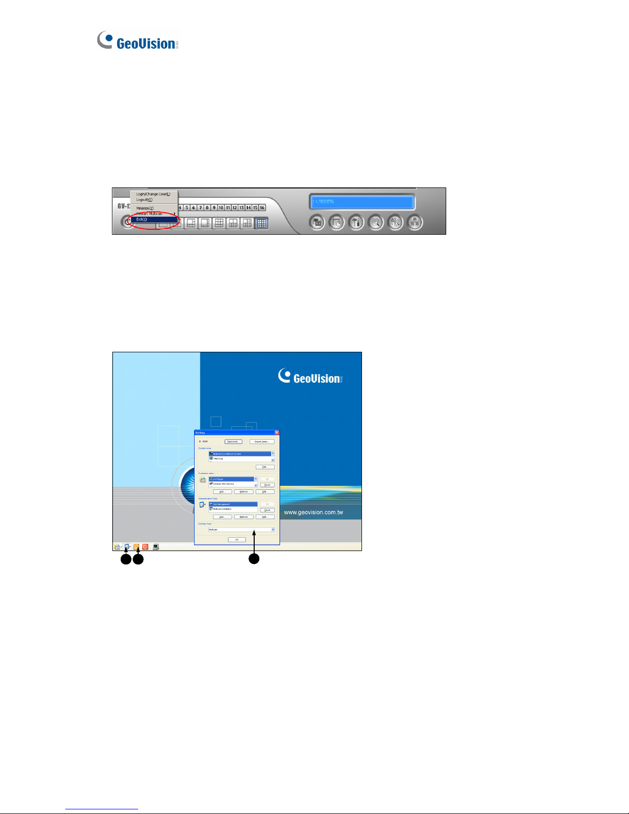
GV-Tower DVR/NVR System is protected by GV-Desktop that is limited to run the selected
programs. If you need to exit to Windows desktop, follow these steps.
1. Exit the main screen to display the GV-Desktop screen.
Figure 3-29
2. Click the Settings button, and type the valid ID and password. The default ID and
Password are “0000”. The Settings dialog box appears.
3. Under Desktop Type, select Windows from the drop-down list, and click OK.
4. Click the Log Off button, and type the ID and Password to display the Windows desktop.
2 4
3
Figure 3-30 The GV-Desktop
28
Page 35
Getting Started
3
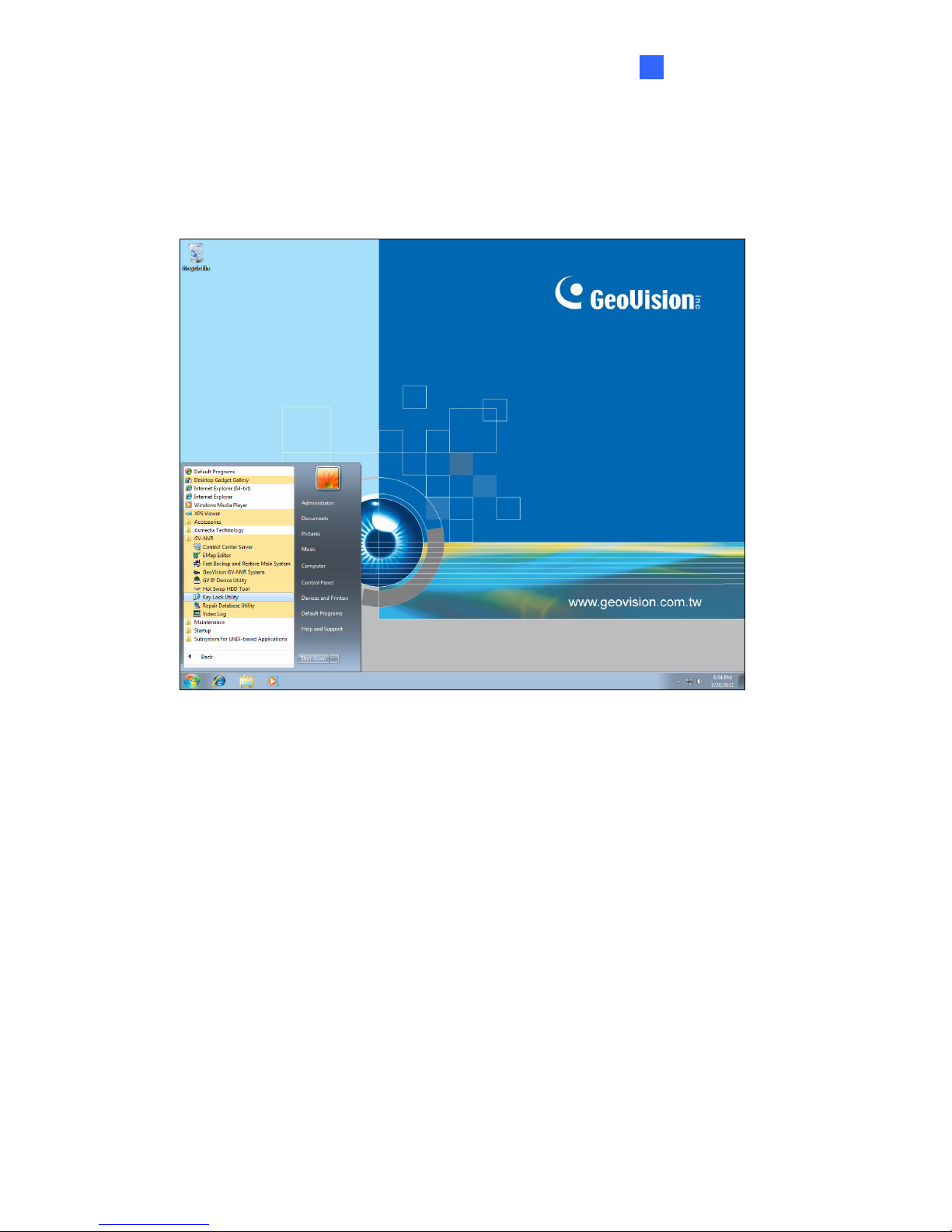
3.9 Returning to GV-Desktop
To return to GV-Desktop, click the Windows Start button, point to All Programs, click
GV-DVR/NVR, and click Key Lock Utility.
Figure 3-31
29
Page 36
3.10 Twin View Display
You can display live view and play back video in two separated monitors.
1. Follow Steps 1 and 2 in 3.7 Configuring the IP Address to access the Control Panel
window. See Figure 3-23.
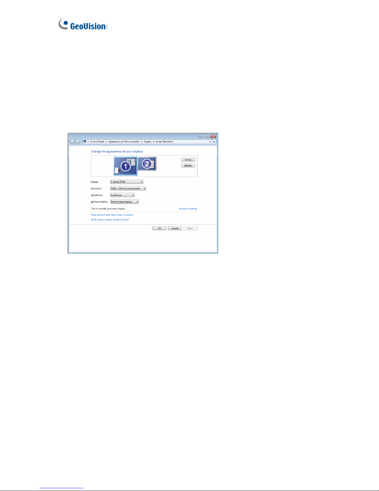
2. In the Control Panel window, click Adjust Screen Resolution under the Appearance and
Personalization section. This dialog box appears.
Figure 3-32
3. Click the Display list. If you do not see multiple monitors listed, check if your additional
monitors are connected with the system properly.
4. Select the primary monitor from the list, and select Make this my main display.
5. Select additional monitors from the list, and select Extend these displays in the Multiple
displays drop-down list.
6. Click Identify. Drag and drop the monitor icons to match the physical arrangement of your
monitors.
30
7. Click OK.
Page 37
Getting Started
3
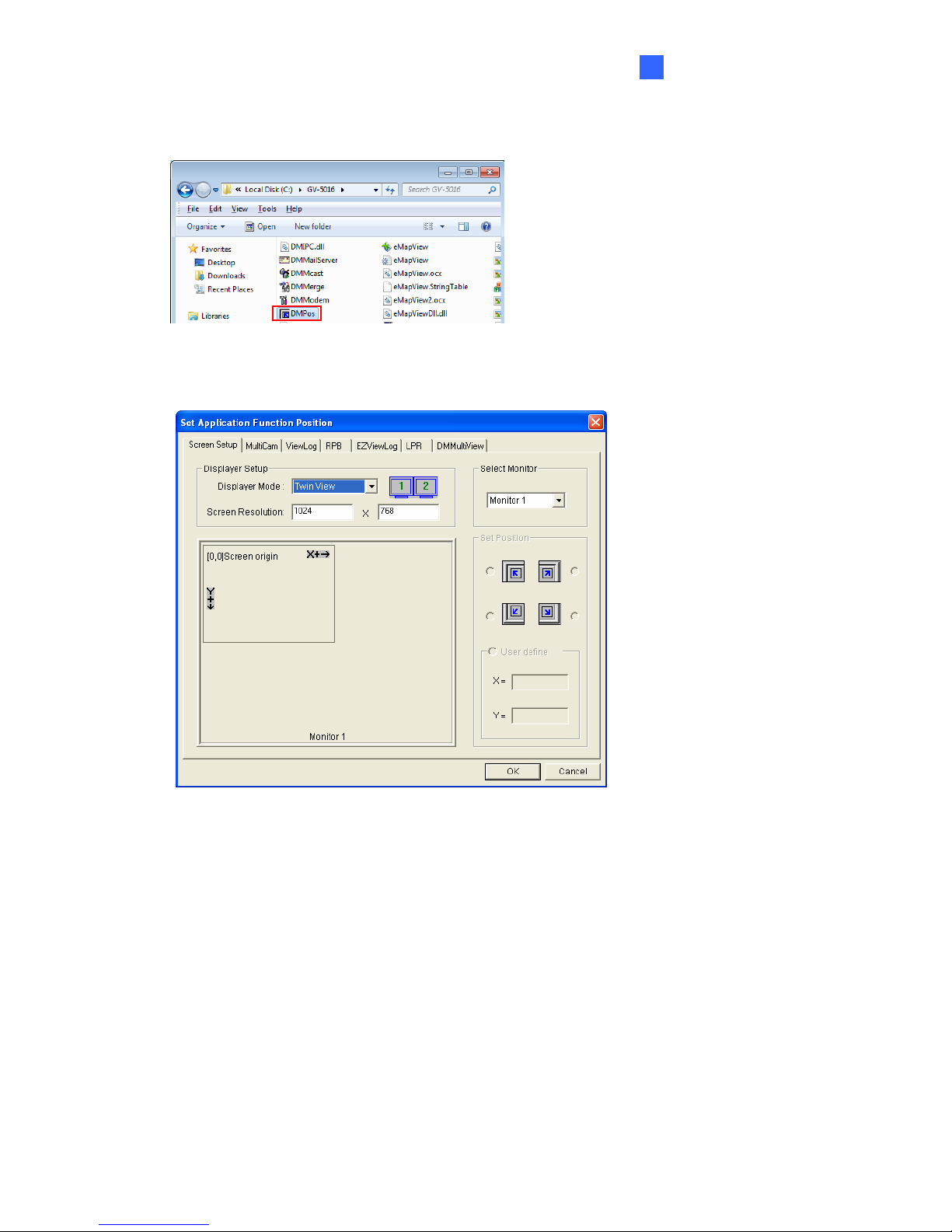
8. Click the Up button on the toolbar, go to the system folder and locate DMPOS.exe.
Figure 3-33
9. Double-click DMPOS.exe. The Set Application Function Position dialog box appears.
Figure 3-34
10. In the Screen Setup tab, select TwinView from the Displayer Mode drop-down list.
11. To define the live view monitor, in the MultiCam tab, select Monitor 1 from the Select
Monitor drop-down list.
12. To define the playback monitor, in the ViewLog tab, select Monitor 2 from the Select
Monitor drop-down list.
13. Click the OK button.
14. Exit and re-start the system. The live view should appear on monitor 1.
15. Click the ViewLog button on the main screen and select Video/Audio Log from the
menu. The ViewLog player should appear on monitor 2.
31
Page 38

3.11 Digital Matrix
To display multiple channels through two monitors, Digital Matrix is thus introduced to provide
a method.
The Digital Matrix includes these features:
z Live view: You can set different live views and screen divisions for each monitor.
z Automatic channel scan: You can set up to 16 scanned pages with different screen
divisions and channels for each monitor.
z Pop-up Alert: You can be alerted by pop-up live videos when motion is detected or I/O
devices are triggered.
3.11.1 Activating Two Monitors
Use Windows Display Property to activate multiple monitors.
1. Follow Steps 1 to 6 in 3.10 Twin View Display to configure the second monitor.
2. Start the GV-System, click the Configure button, click Accessories, select Digital
Matrix Setting, select monitors from the Display list and select Activate for each
monitor. All monitors must be activated one by one.
3. Click Apply. Your additional monitor should now display the channels seen on the
primary monitor.
32
Page 39
Getting Started
3
3.11.2 Setting Live View
You can set different live views and screen divisions for each monitor.
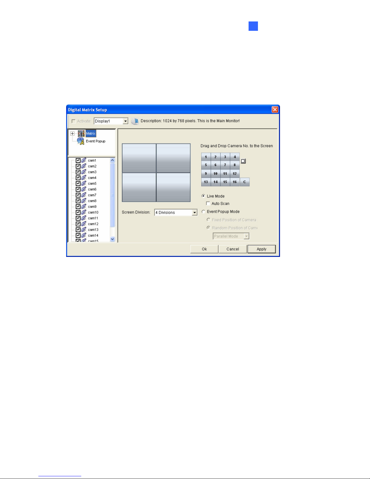
1. On the main screen, click the Configure button, click Accessories, and select Digital
Matrix Setting. This dialog box appears.
Figure 3-35
2. Use the Display list to select the monitor to be configured.
3. Select Screen Division.
4. Drag and drop the camera numbers to the desired positions on the divisions. To clear the
assignment, drag and drop the “C” icon to that position.
5. Select Live Mode.
6. Repeat above steps to configure other monitors.
7. Click OK to apply the settings.
33
Page 40
3.11.3 Setting Scanned Pages
You can set up to 16 scanned pages with different screen divisions and channels for each
monitor.
1. Use the Display list to select the monitor to be configured.
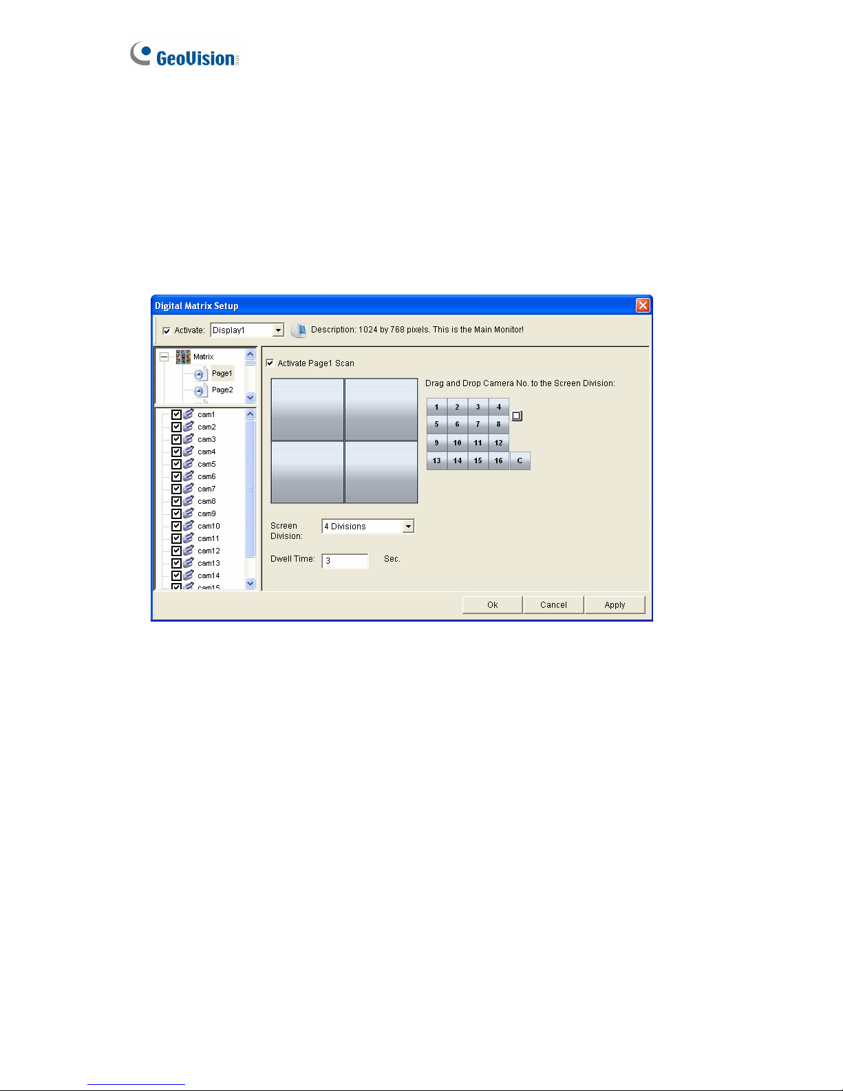
2. In the upper-left column, expand the Matrix folder tree, and click Page 1. This page
appears.
Figure 3-36
3. Select Activate Page 1 Scan.
4. Select Screen Division.
5. Drag and drop the camera numbers to the desired positions on the divisions. To clear the
assignment, drag and drop the “C” icon to that position.
6. Specify Dwell Time for how long this scanned page remains on the monitor.
7. Repeat Steps 2 to 5 to configure more scanned pages for the specific monitor.
8. Repeat Steps 1 to 7 to configure scanned pages for the second monitor.
9. In the upper-left column, click the Matrix icon and return to Figure 3-35.
10. Select Auto Scan.
34
11. Click OK to start scanning among pages.
Page 41
Getting Started
3
3.11.4 Setting Pop-up Alert
You can be alerted by pop-up live videos when motion is detected or I/O devices are
triggered.
1. Use the Display list to select the monitor to be configured.
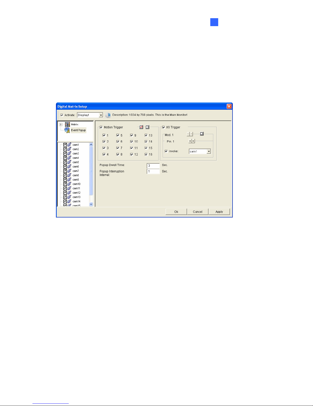
2. In the upper-left column, click Event Popup. This page appears.
Figure 3-37
Motion Trigger: The live video of selected cameras pops up when motion is detected.
I/O Trigger: The live video of assigned camera pops up when the selected input
device is triggered.
Popup Dwell Time: Specify the amount of time that a pop-up live video remains in the
foreground.
Popup Interruption Interval: Specify the interval between camera pop-ups. This
option is useful when several cameras are activated for pop-up alert at the same time.
3. Use the Display list to select other monitors for setup.
4. After above settings, click the Matrix icon and return to Figure 3-36.
5. Select Event Popup Mode. Then select Fixed Position of Camera or Random Position
of Camera. For these two options, see 3.11.4.1 Setting Pop-up Positions.
6. Click OK.
35
7. Start monitoring. When motion is detected or the input device is triggered, the live video
will pop up for alert.
Page 42
3.11.4.1 Setting Pop-up Positions
When you select Random Position of Camera, you can decide the positions for pop-up
cameras.
Fixed Position of Camera: The cameras pop up in their assigned positions. To assign
positions, select Screen Division. Then drag and drop the cameras number to the
desired potions on the divisions.
Random Position of Camera: The positions of pop-up cameras are based on the
sequence order of triggers. There are two modes for this position:
1. Cascade Mode: This mode can avoid the same cameras popping up on different
monitors. This is suggested to be used when multiple monitors are placed close to
each other.
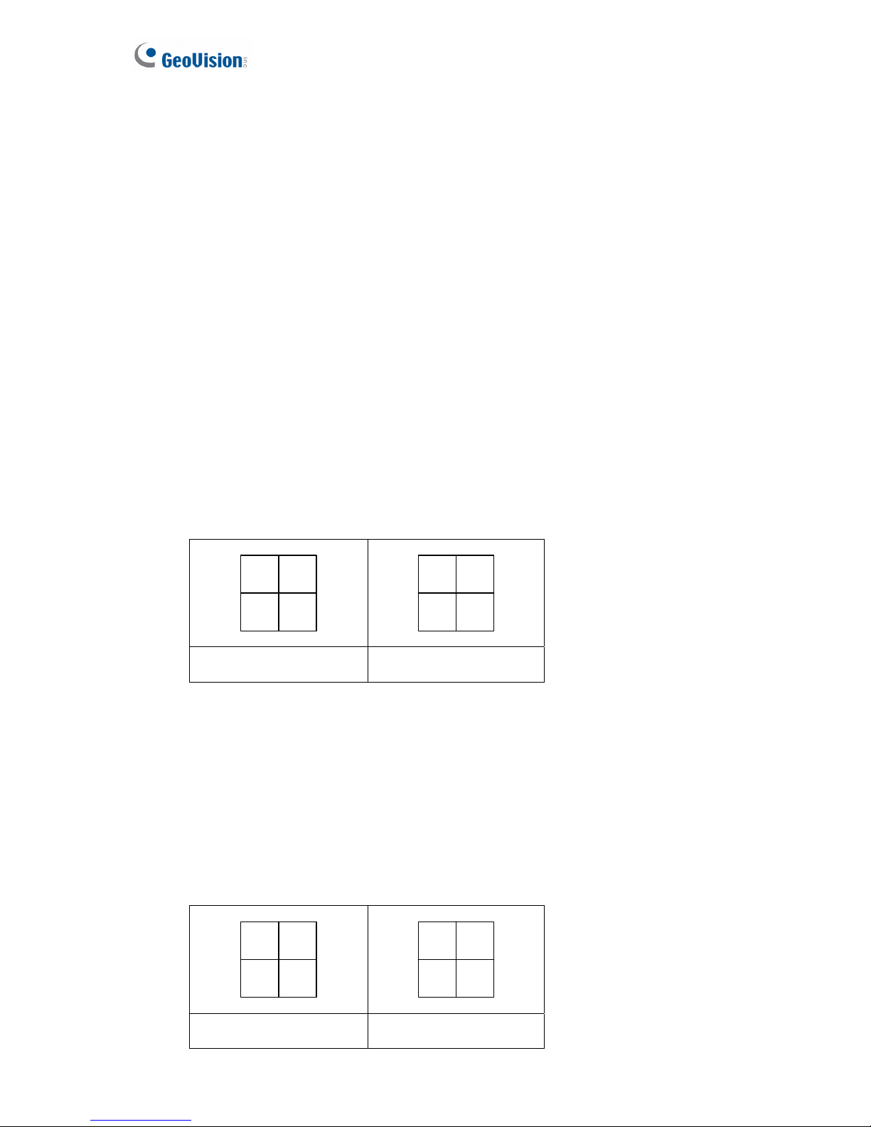
Example:
Camera 1, Camera 2, Camera 3, Camera 4 and Camera 5 are assigned for pop-up
alert on both Monitor 1 and Monitor 2. Monitor 1 is set at 4 screen divisions. When
the five cameras are triggered at same time, the first 4 cameras show up on Monitor
1 and the 5th on Monitor 2.
21
34
5
Monitor 1 Monitor 2
2. Parallel Mode: This mode allows the same cameras simultaneously pop up on
different monitors. This is suggested to be used when multiple monitors are placed
in separate rooms.
Example:
Camera 1, Camera 2, Camera 3 and Camera 4 are assigned for pop-up alert on both
Monitor 1 and Monitor 2. When the four cameras are triggered at the same time, they
will show up simultaneously on both Monitor 1 and Monitor 2.
36
21
34
21
34
Monitor 1 Monitor 2
Page 43

Getting Started
3
3.11.5 Setting Live View with Pop-up Alert
You can set a different live view mode with pop-up alert together for each monitor. When alert
events occur, the live video of the associated camera will pop up on the assigned monitor to
replace its live view mode.
1. To configure live view mode, follow the instructions in 3.11.2 Setting Live View.
2. To configure pop-up alert, in the upper left column, click Event Popup. Figure 3-37
appears.
3. Configure Motion Trigger, I/O Trigger, Popup Dwell Time and Popup Interruption
Interval for each monitor. For details see 3.11.4 Setting Pop-up Alert.
4. Click the Matrix icon and return to Figure 3-35. Ensure the Live Mode option is selected.
5. Click OK. The live view mode you configured for each monitor is displayed.
6. Start monitoring. When alert events occur, the associated camera will pop up on the
desired monitor.
37
Page 44
3.12 System Restoration
3.12.1 Restoring System
You can restore preinstalled files once they are damaged by running the recovery from the
hidden partition. To restore the operating system and all preinstalled software, follow the steps
below.
Note: After recovery, you need to re-install all settings and passwords. But the recovery will
not delete your recording files saved in the other partitions since it only reformats the partition
C.
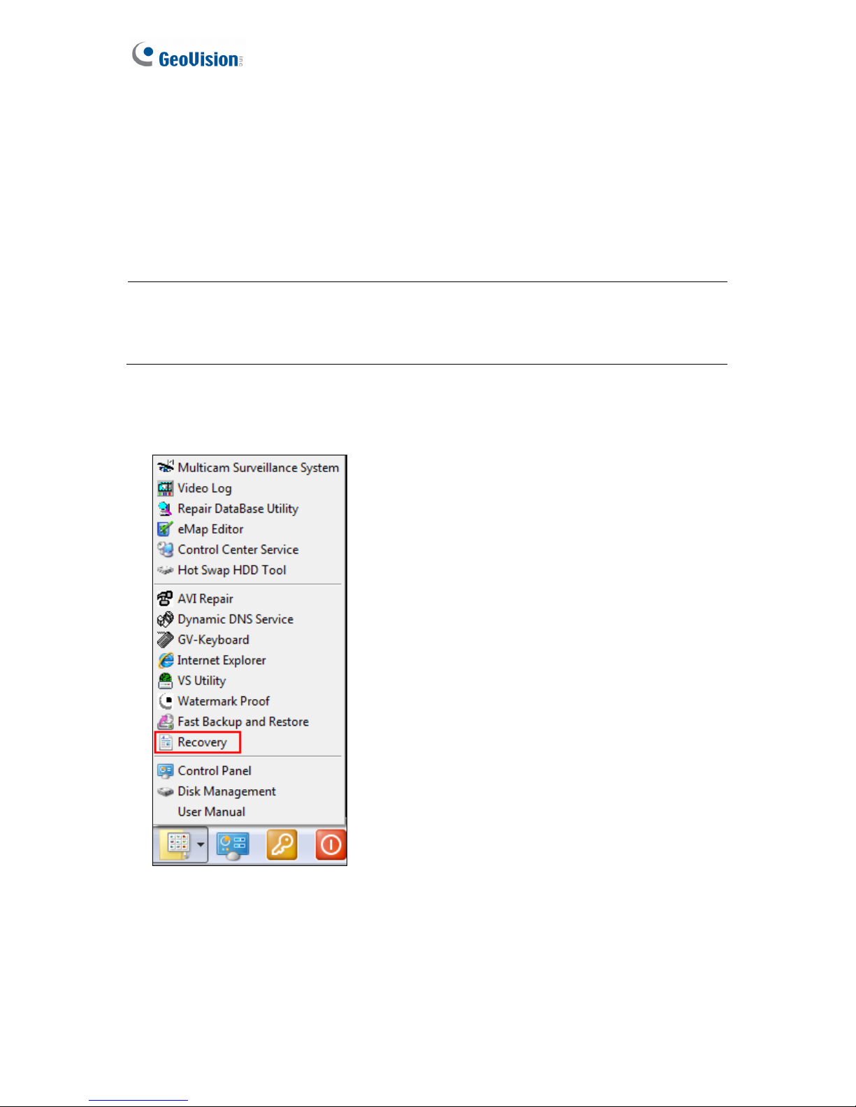
1. On the GV-Desktop, click the Program button and select Recovery. The system will run
this command by itself.
Figure 3-38
2. Restart the GV-Tower DVR/NVR System.
3. Press F11 button several times to avoid accessing the system.
38
Page 45
Getting Started
3
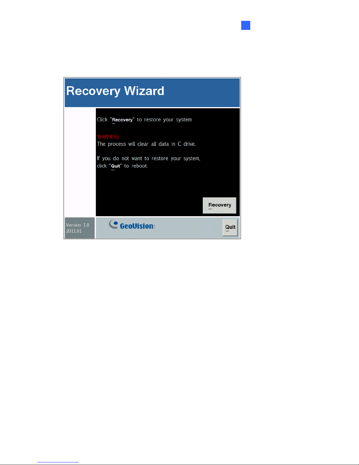
4. When the below screen appears, press the Recovery button.
Figure 3-39
5. When the restoring process is completed, the screen will automatically show the
GV-Desktop. And the system will restore the default values.
39
Page 46
3.12.2 Changing Video Standard after Recovery
The default video standard after recovery is set to NTSC. If the video standard in your country
is PAL, remember to configure the GV-Tower DVR/NVR System for PAL after recovery .
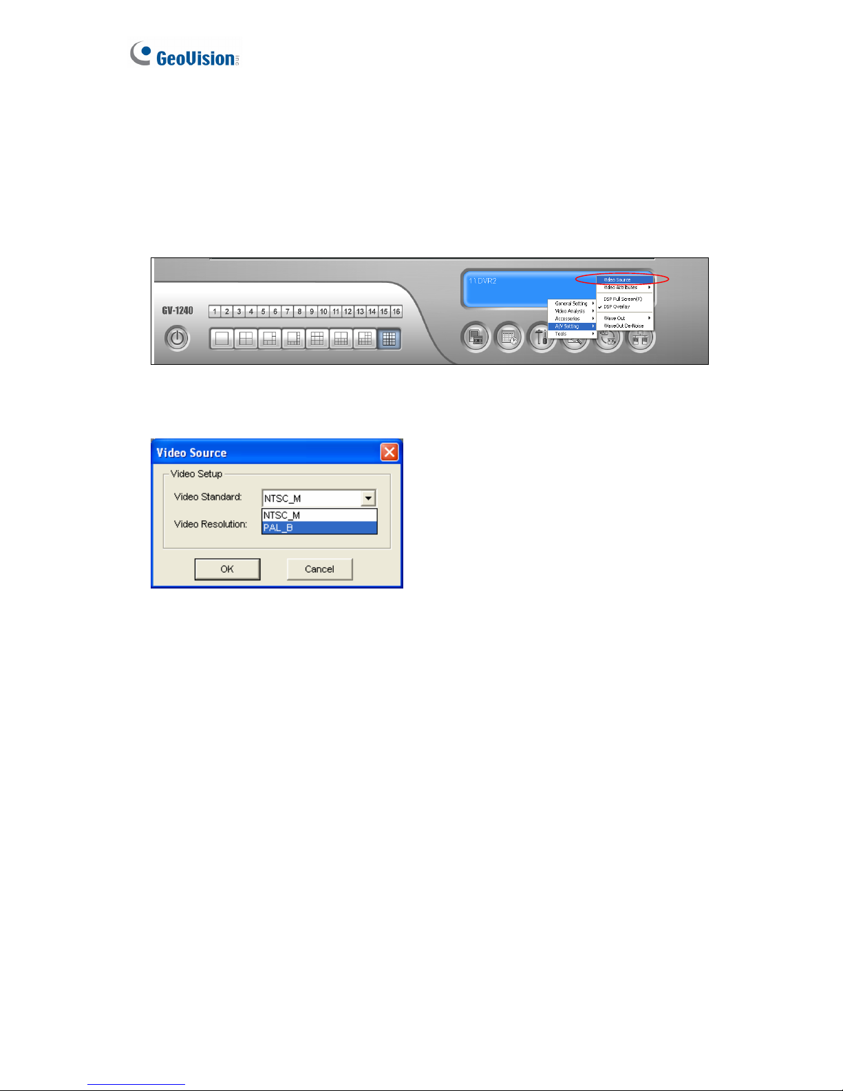
1. Click the Configure button, point to A/V Setting, and then select Video Source.
Figure 3-40
2. In the Video Standard field, select PAL from the drop-down list, and click OK.
Figure 3-41
40
Page 47

Getting Started
41
3
3.13 Updating GV-Tower DVR/NVR System
If you like to update your GV-Tower DVR/NVR System, contact your dealer for more
information.
Before contacting your dealer, you may check software update news at our website:
http://www.geovision.com.tw
Page 48
Chapter 4 Health Analysis
GeoVision offers health analysis to GV-Tower DVR/NVR System. The service is intended to
give diagnosis for early and immediate detection of problems.
It is recommended to have the health analysis during the first week after you install the
GV-Tower DVR/NVR System, and then have the checkup every three months. It will take 5
working days for response.
Please prepare the following data for analysis, and send to [email protected]
z System Settings
z System Log
z Information of your computer system (Processor; Drives; Voltage, Temperature and
Fans)
4.1 System Settings
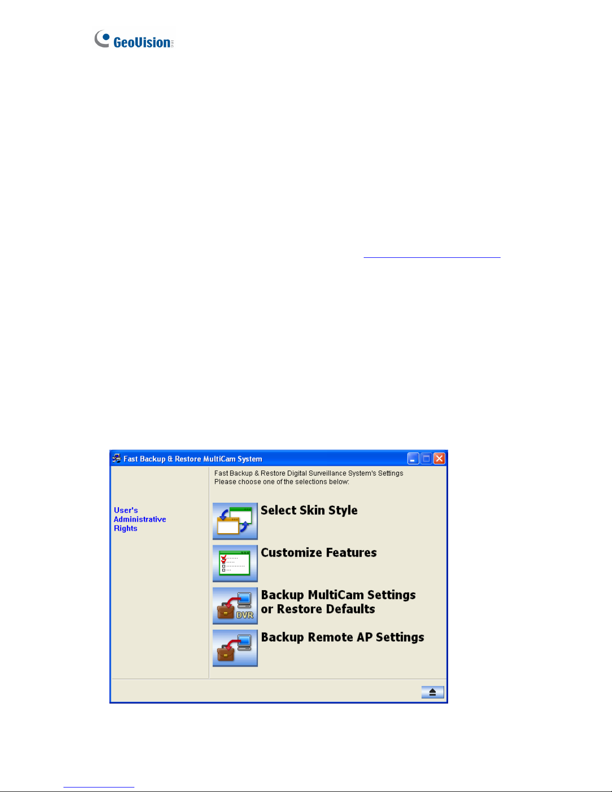
Please back up your system configurations using the Fast Backup and Restore application.
1. Run Fast Backup & Restore Main System from the Start menu.
Figure 4-1
42
Page 49
Health Analysis
4
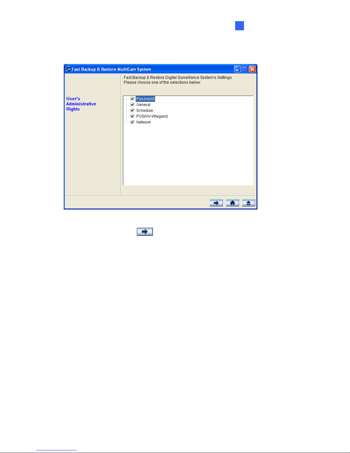
2. Select Backup MultiCam Settings or Restore Defaults, and select Backup Current
System. This dialog box appears.
Figure 4-2
3. Press the Next Step button
to back up all your system settings. The Save As
dialog box appears.
4. Select the destination drive to store the backup file. When the backup is complete, this
message “Successfully Backup MultiCam System Settings” will appear.
43
Page 50
4.2 System Log
Please provide the sys*.mdb files of system log. The files by default are saved at C:\GV
folder\database. If you have modified the default location, you can check the path by the
following steps:
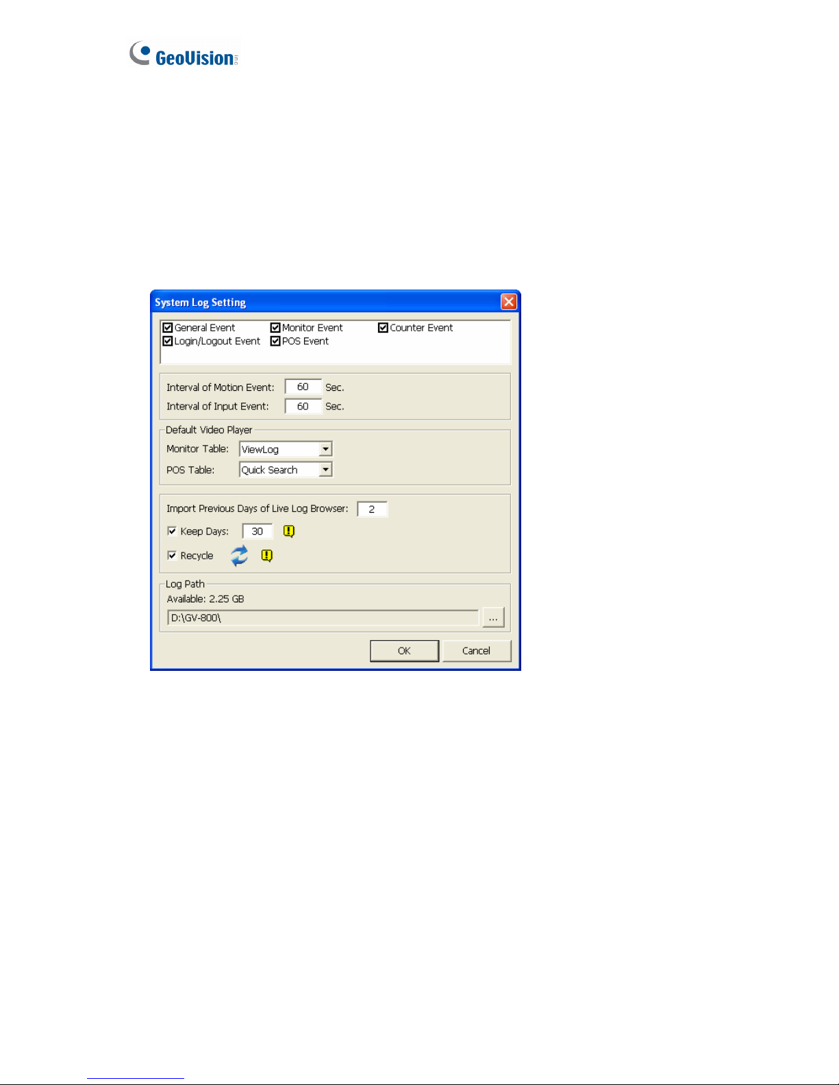
1. Click the Configure button on the Main System, select System Configure, and then
select System Log Setting. This dialog box appears.
Figure 4-3
2. The location of your system log is listed after Log Path.
44
Page 51
Health Analysis
4
4.3 Information of Your Computer System
To get the information of your computer system, please follow the steps below to install the
free software PC WIZARD. By using the software, the following computer information can be
easily collected and saved for analysis:
z Processor: includes Type, Frequency, Data Cache L1, Trace Cache L1, Cache L2,
Voltage, Processor Temperature, FPU Coprocessor.
z Drives: includes Number of Hard Disk, Number of Drive, Total Size and Free Space of
Drive.
z Voltage, Temperature and Fans: includes Monitoring Chip, Voltage CPU, Chassis Fan,
Processor Temperature, Mainboard Temperature, Hard Disk Temperature.
1. Download and install PC WIZARD from http://www.cpuid.com/pcwizard.php
.
2. After installation, run the program.
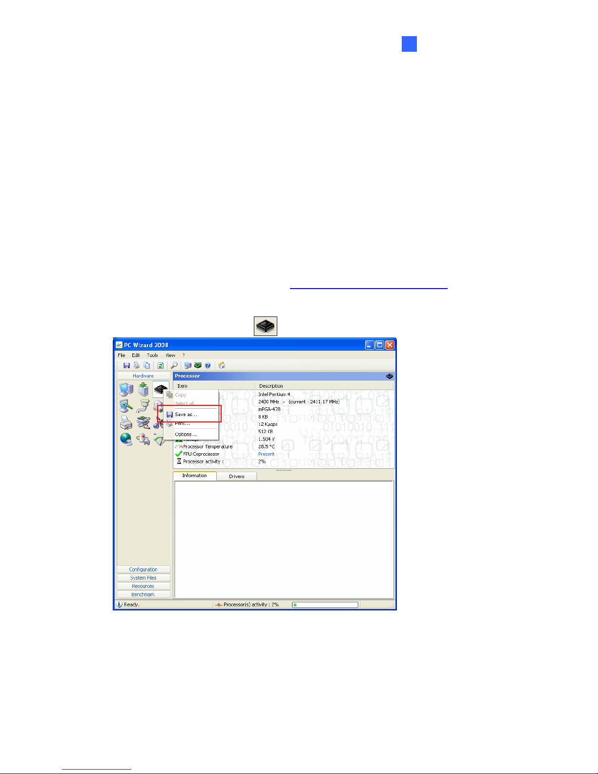
3. Right-click the Processor icon
and click Save as.
Figure 4-4
45
Page 52
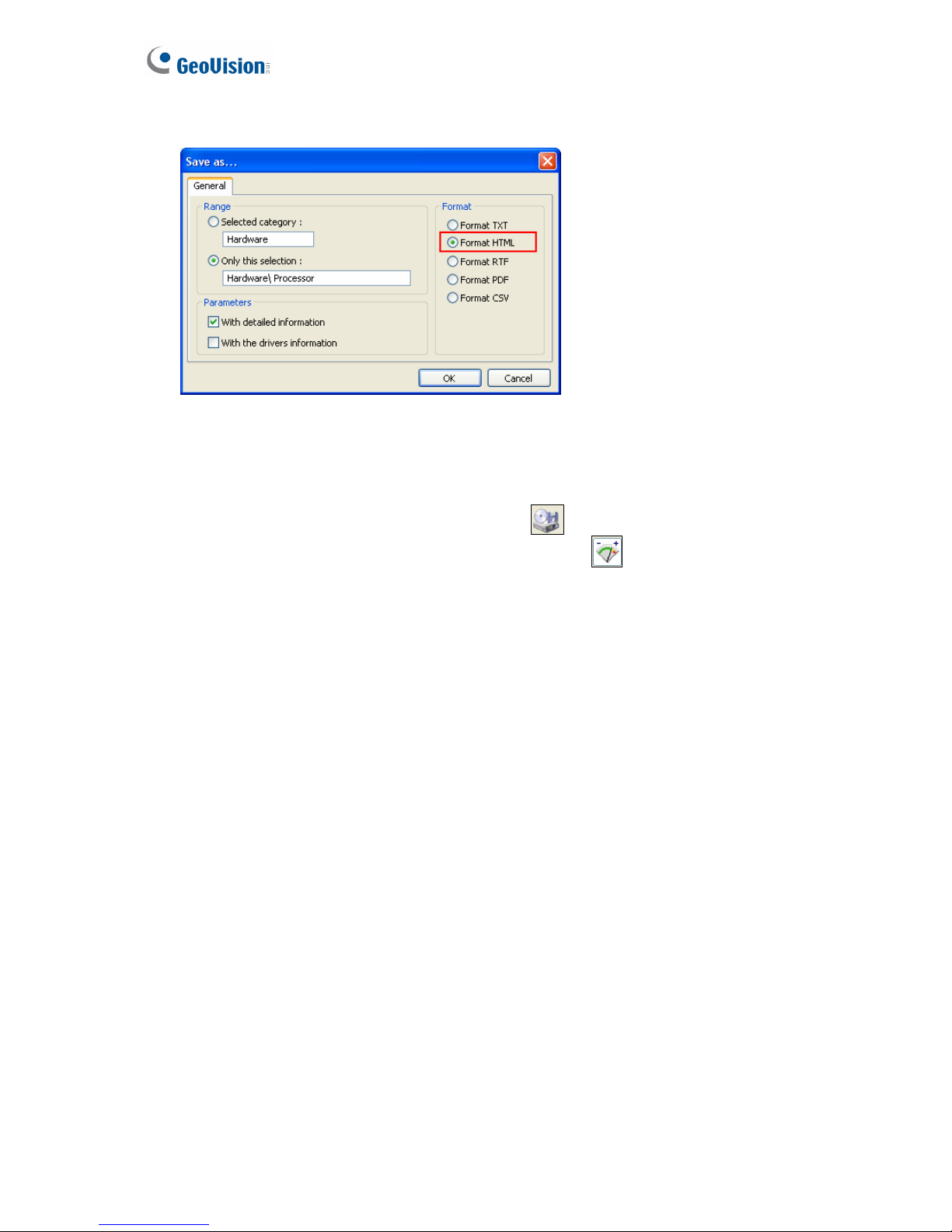
4. In the Save As dialog box, select Format HTML and click OK.
Figure 4-5
5. Select the Save location, type the file name, and then click Save to save the Processor
information as HTML file.
6. Repeat Steps 3-5 to save the Drives information as HTML file.
7. To save the Voltage, Temperature and Fans information , please follow these
steps:
A. Click the Voltage, Temperature and Fans icon. The related data is displayed at the
right window.
B. Click the first item Monitoring Chip.
C. Click Edit on the menu bar and click Select All to highlight all the contents.
D. Click Edit on the menu bar and select Copy.
E. Open a Notepad. Paste and save the information to TXT file.
46
Page 53
Health Analysis
47
4
4.4 Health Analysis Form
Please send the related data for analysis along with this Health Analysis Form to
.
Health Analysis of GV-Tower DVR/NVR System
Contact Person: Title:
Company Name:
Telephone: (O) (H)
Fax:
E-Mail:
Model:
Bar Code:
4.5 Check List
Read this check list before submitting the health analysis request:
z System Settings- EXE file
z System Log- sys*.mdb
z Computer System- Processor information of HTML file
z Computer System- Drives information of HTML file
z Computer System- Voltage, Temperature and Fans information of TXT file
z Health Analysis Form
Page 54
Chapter 5 Troubleshooting
GV-Tower DVR/NVR System stops responding (aka “crashed” or “froze”).
If your GV-Tower DVR/NVR System is not responding to your clicking, typing, or mouse
movements, try these steps to get your GV-Tower DVR/NVR System back on track. Please
note that you will lose any unsaved changes in all open applications.
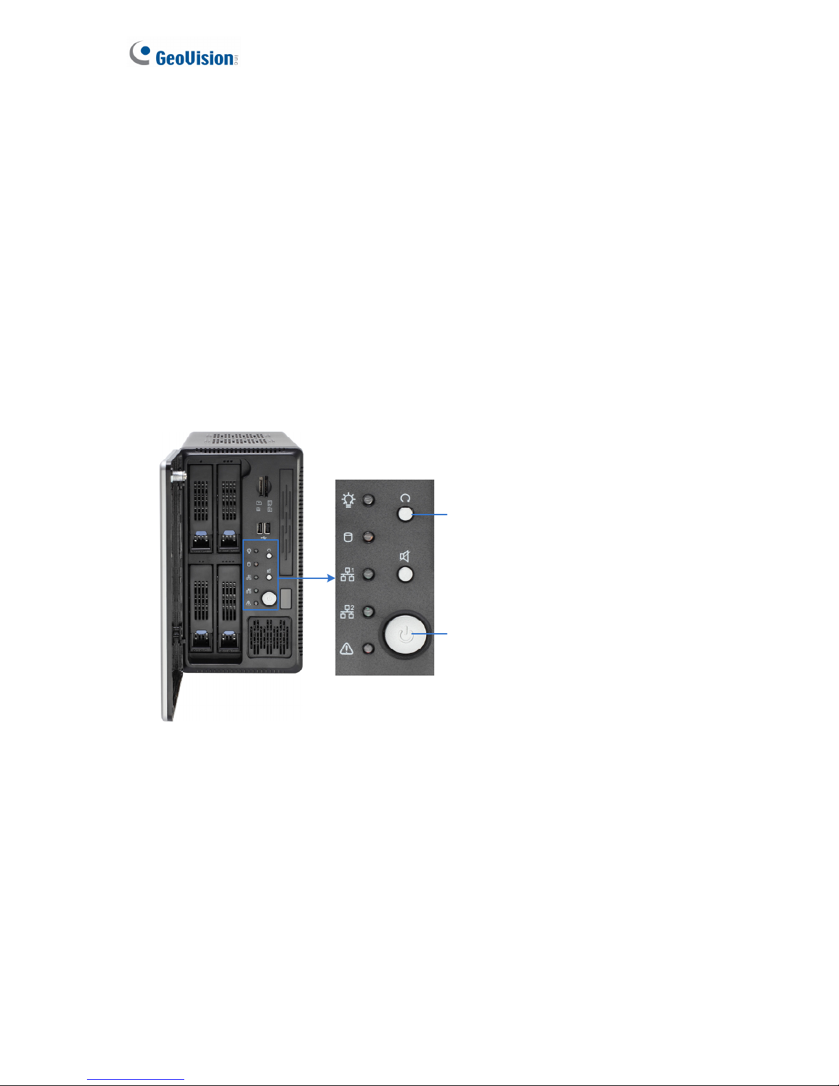
1. Restart your GV-Tower DVR/NVR System by pressing the Reset button on the front
panel.
2. If your GV-Tower DVR/NVR System is still unresponsive, press the Power button to shut
it down. Wait 30 seconds and then restart your GV-Tower DVR/NVR System.
Reset
Power
Figure 5-1
48
Page 55
Troubleshooting
5
GV-Tower DVR/NVR System hard disk corrupts.
If you are experiencing file system corruption problems, such as lost clusters, cross-linked
files or invalid files or directories, try these steps:
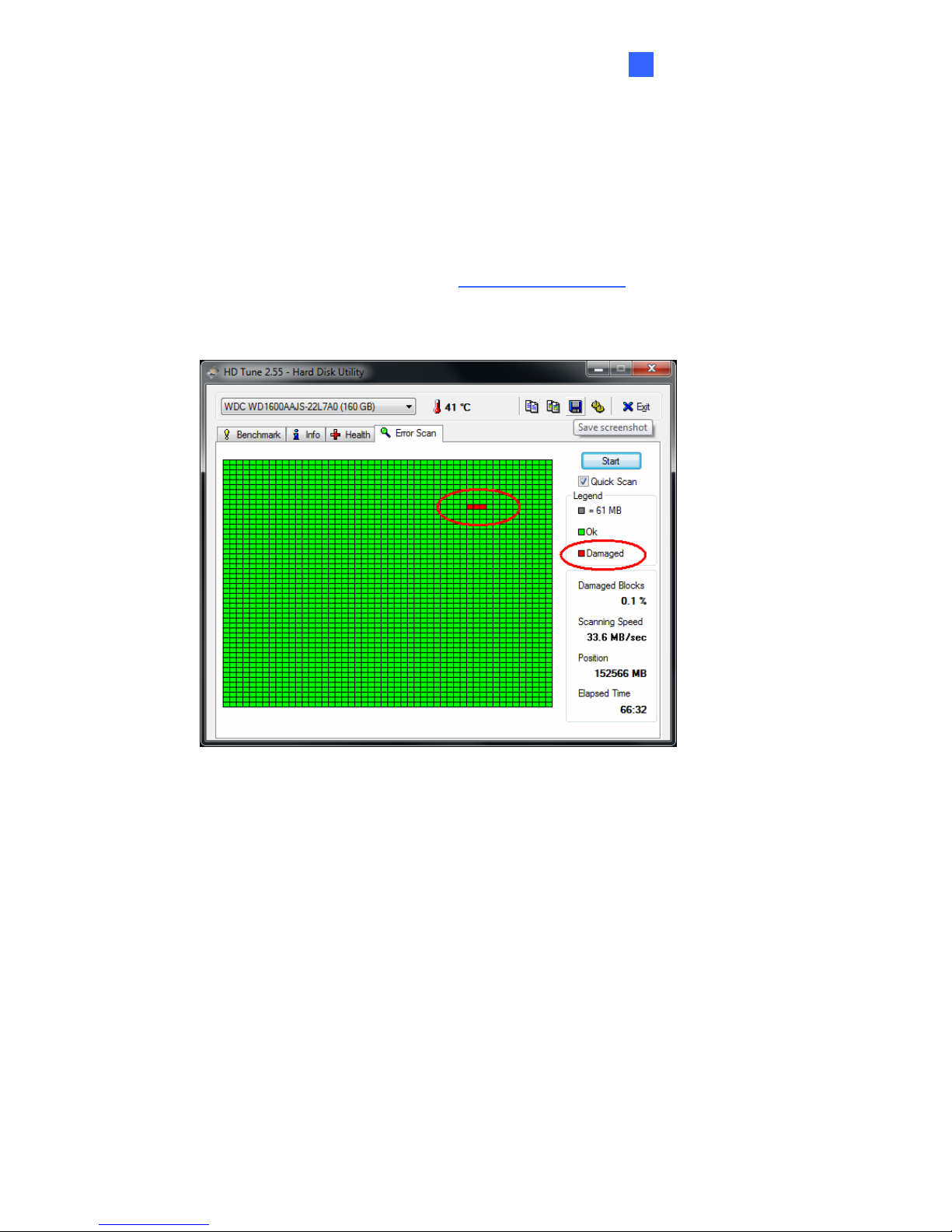
1. Use the HD Tune utility to scan the hard disk for errors. Follow these steps:
A. Download and install HD Tune from http://www.hdtune.com/
B. Click the Error Scan tab and click Start to scan. Any found defects will be shown as
red blocks (see Figure 5-2).
Figure 5-2
C. If your hard disk drive is damaged, replace a new one.
49
Page 56
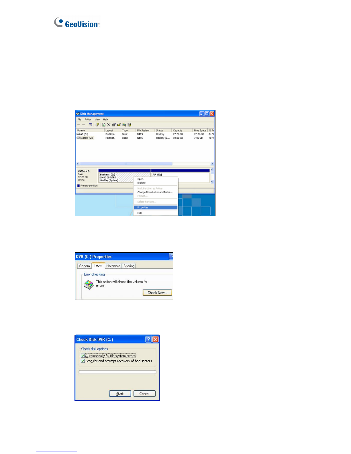
2. If the HD Tune utility does not find any defects, use the Windows built-in utility to attempt
to fix the errors. Follow these steps:
A. On the GV-Desktop, click the Programs button, and select Disk Management. See
Figure 3-9.
B. Right-click the desired hard disk and select Properties from the file menu to display
the Properties window.
Figure 5-3
C. Click the Tools tab in the upper portion of the window.
D. Under Error-checking, click the Check Now button.
Figure 5-4
E. Select Automatically fix file system errors and Scan for and attempt recovery of
bad sectors.
Figure 5-5
F. Click Start.
50
Page 57

Troubleshooting
51
5
3. If the problem persists, replace a hard disk drive.
GV-Tower DVR/NVR System suffers virus attack.
GV-Tower DVR/NVR System is designed and optimized for Windows 7 platform. It may be
vulnerable to newly created worms and exploits that attack any of the underlying operating
system’s previously undocumented flaws. If your GV-Tower DVR/NVR System suffers virus
attack, try restoring the operating system and GV-System Software by using the Recovery.
Refer to 3.12.1 Restoring System.
GV-Tower DVR System has video and/or audio lost.
If your GV-Tower DVR System fails to show video, audio or both, try these steps:
1. Check the video/audio connection. Make sure one end of the LFH audio & video cable is
securely connected to the video/audio device, and the other end to the video/audio port of
the GV-Tower DVR System.
2. Make sure the video/audio device is turned on.
3. Switch the cable from the functional channel to the non-functional channel, and vice versa.
If the previously non-functional channel is now able to deliver video/audio, you should
check the video/audio device itself and its related cables.
The screen image appears distorted or jitters.
If the screen image seems to be distorted, jitter, or not to look right, try these steps:
1. Make sure the video standard in your country matches the setting in the GV-Tower
DVR/NVR System. Refer to 3.12.2 Changing Video Standard after Recovery.
2. Make sure the camera and its cable are not damaged or frayed. Try to replace a camera
or camera cable to see if this fixes the problem.
How can I find more help?
1. Visit our website at http://www.geovision.com.tw/english/4_1.asp
2. Write us at [email protected]
Page 58
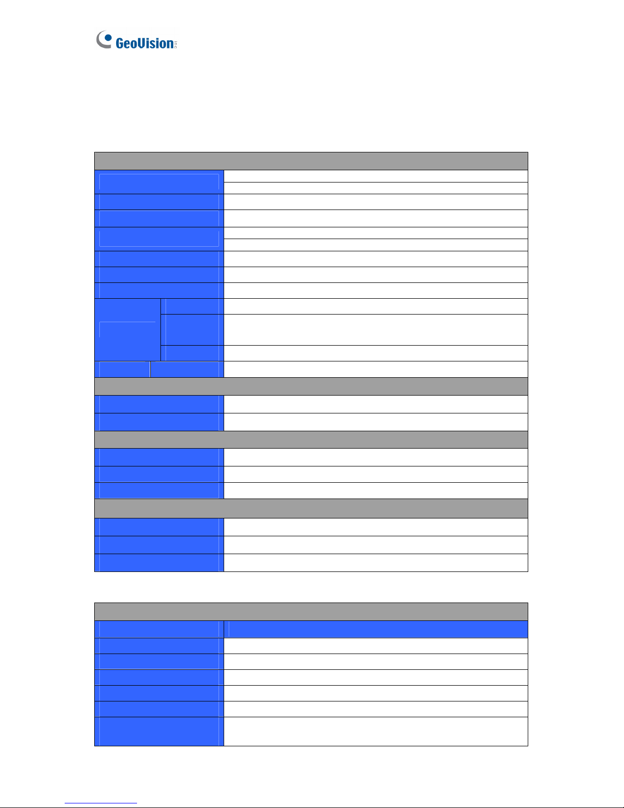
Specifications
GV-Tower DVR/NVR System
Hardware
System
Intel Core i3 Processor
CPU
Intel Core i5 Processor (optional)
RAM
4 GB Dual Channels
No. of HDD
4 (3.5” HDD)
16 GB (DOM)
Internal Storage
32 GB (DOM) bundled with i5 Processor
OS
64-bit Windows Embedded Standard 7
DirectX
11
Power
120 W, 100-230 V, 47-63 Hz
Ethernet
RJ-45, 10 / 100 / 1000 Mbps x 2
Video
Output
VGA and HDMI
Connector
USB 2.0
Rear: 6 ports
Fan 7 cm (3 1/8")
2 units
Environment
Operating Temp. 0 ~ 45 °C / 32 ~ 113 °F
Humidity 0 ~ 80% RH (non-condensing)
Physical
Color Black
Dimensions (W x H x D)
260 x 140 x 260 mm / 10.24 x 5.51 x 10.24 in
Net Weight 6.3 kg / 13.8 lb (± 1 kg / 2.2 lb)
Sensor and Alarm (Optional)
GV-IO Box 4 Ports
4 inputs, 4 outputs
GV-IO Box 8 Ports
8 inputs, 8 outputs
GV-IO Box 16 Ports
16 inputs, 16 outputs
Software
Video and Audio
Model GV-Tower DVR System
Video Standard NTSC, PAL
Video Input
16 channels
Video Input Level 1.0 Vp-p (± 10%) composite, 75 Ω
Audio Input
16 channels
Audio Input Level 0.5 ~ 1 Vp-p composite
Video Compression
Format
HW: H.264
SW: Geo MPEG4, Geo H.264, MJPEG
52
Page 59
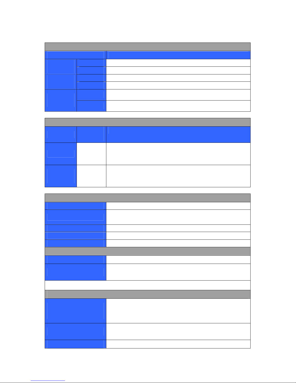
Specifications
Video and Audio
Model GV-Tower DVR System
NTSC
480 FPS
Display
Rate (Max)
PAL
400 FPS
NTSC
HW: 480 (D1)
Recording
Rate (Max)
PAL
HW: 400 (D1)
NTSC
HW: 704 x 480
SW: 352 x 240
Video
Resolution
PAL
HW: 704 x 576
SW: 352 x 288
Video and Audio
Model
GV-Tower
NVR (GV)
GV-Tower NVR (3rd Party)
Video Input
32
channels
1, 2, 4, 6, 8, 10, 12, 16, 18, 20, 22, 24, 26, 28, 30, 32 channels
Audio
Input
32
channels
1, 2, 4, 6, 8, 10, 12, 16, 18, 20, 22, 24, 26, 28, 30, 32 channels
Live View and Playback
Image Control
Contrast / Brightness / Saturation / Hue
Recording Mode
Round the Clock / Motion Detection / Sensor Detection / Pre &
Post Recording / Schedule Recording
Pre Recording
1~ 45 min.
Instant Playback
10 sec. / 30 sec. / 1 min. / 5 min.
Watermark
Supported
Search and Backup
Search Method Date / Time / Camera / Event Type
Backup Type
DVD+R (DL) / DVD-R (DL) / DVD+R / DVD+RW / DVD-R /
DVD-RW / CD-R / CD-RW
Note: For backup function, you need to connect an external USB DVD/CD burner.
Remote Monitoring
Monitoring
Environment
Web browser (IE, Chrome, Firefox and Safari)
Mobile device (Android Smartphone and tablet; iPad, iPhone
and iPod Touch)
Live View
Max. 32–channel multi views (Up to 200 channels connection
to GV-Tower System)
Network Type
LAN, WAN, Internet
53
Page 60
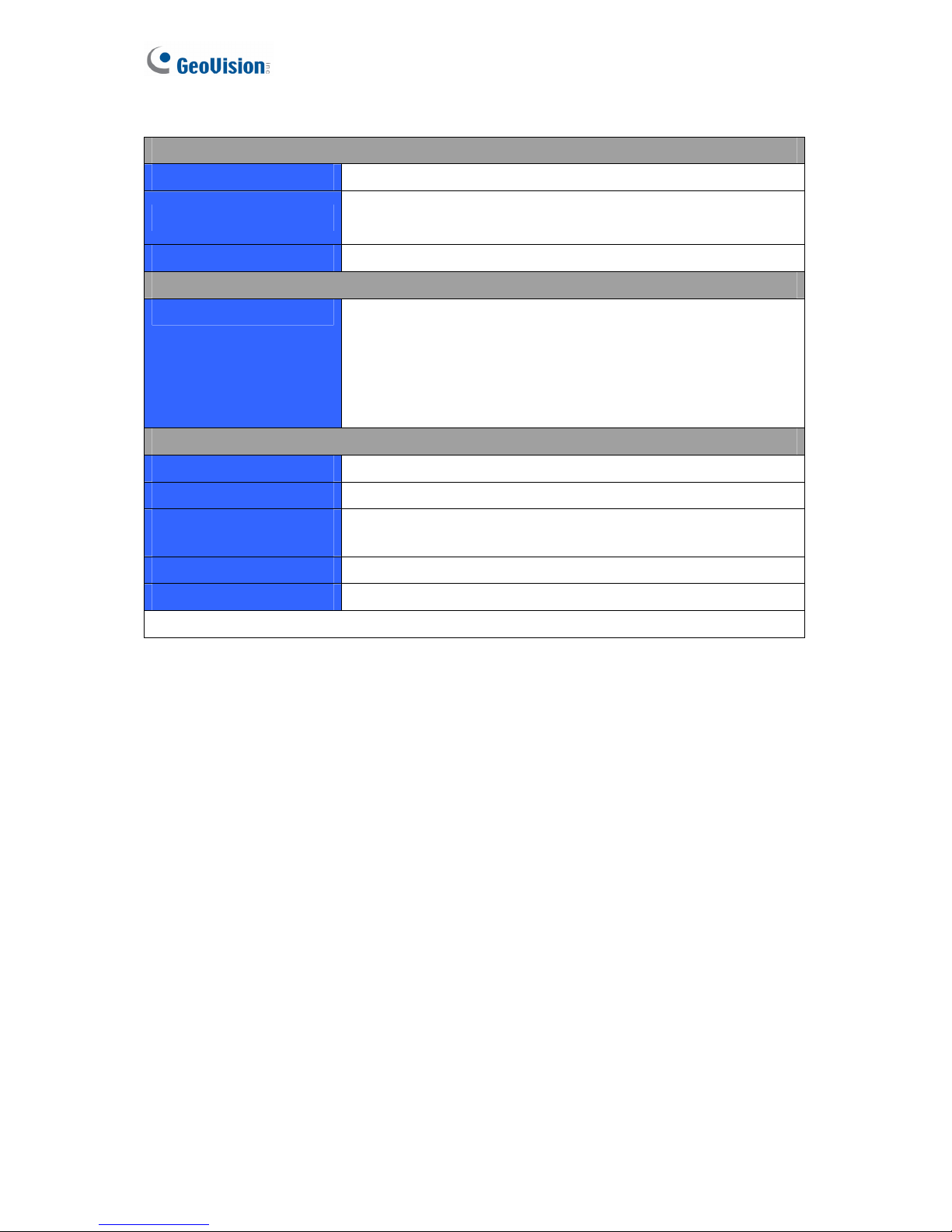
54
System Monitoring and Recovery
Power Restoration
Automatic restart after power outage
Monitoring
Two independent Watchdogs
(Hardware Watchdog + Software Watchdog)
Recovery
Automatic system rebuild from internal hard disk.
Language
Type
Arabic / Bulgarian / Czech / Danish / Dutch / English / Finnish /
French / German / Greek / Hebrew / Hungarian / Italian /
Japanese / Lithuanian / Norwegian / Polish / Portuguese /
Romanian / Russian / Serbian / Simplified Chinese / Slovakian
/ Slovenian / Spanish / Swedish / Thai / Traditional Chinese /
Turkish
Software License
Free License 32 channels from GV-IP devices
Maximum License 32 channels from third-party IP devices
Increment for Each
License
1 to 32 third-party IP cameras at an increment of 2
Optional Combinations N/A
Dongle Type Internal or external
Note: The Maximum License is a paid service.
*All specifications are subject to change without notice.
Page 61
Appendix
Appendix
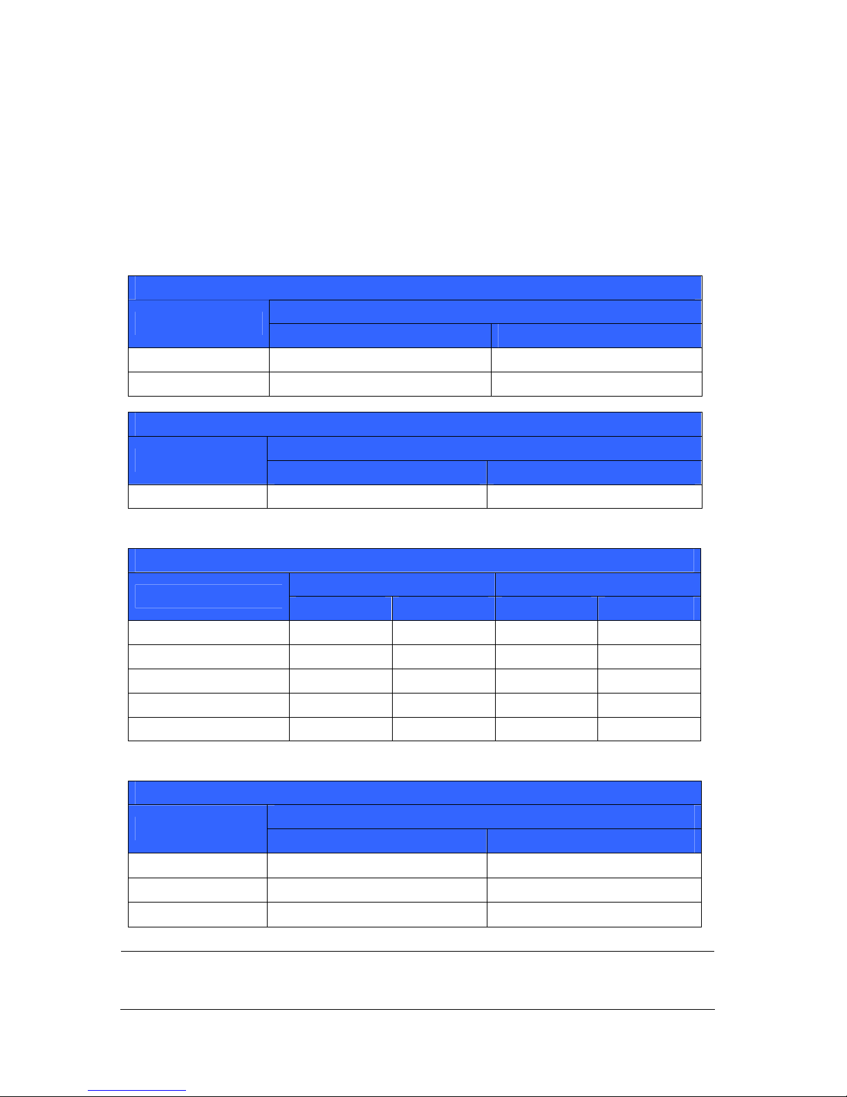
A. Hard Disk Requirements
The total of recording frame rates that you can assign to a single hard disk is listed as below:
Frame rate limit in a single hard disk when connecting to analog cameras
Analog Cameras / SW Compression
MPEG4
Video Resolution
NTSC PAL
CIF 960 FPS 800 FPS
VGA/D1 480 FPS 400 FPS
Analog Cameras / HW Compression
H.264
Video Resolution
NTSC PAL
D1 480 FPS 400 FPS
Frame rate limit in a single hard disk when connecting to IP cameras
IP Cameras
H.264 MJPEG
Video resolution
Frame Rate Bitrate Frame Rate Bitrate
5 MP (2560 x 1920) 220 FPS 8.5 Mbit/s 80 FPS 30.4 Mbit/s
4 MP (2048 x 1944) 330 FPS 10.4 Mbit/s 105 FPS 40.53 Mbit/s
3 MP (2048 x 1536) 440 FPS 9.83 Mbit/s 140 FPS 38.67 Mbit/s
2 MP (1920 x 1080) 660 FPS 12.59 Mbit/s 210 FPS 44.93 Mbit/s
1.3 MP (1280 x 1024) 660 FPS 6.16 Mbit/s 300 FPS 32.26 Mbit/s
Frame rate limit in a single hard disk when connecting to SDI cameras
Hardware Compression
H.264
Video Resolution
NTSC PAL
1080p
360 FPS 300 FPS
1080i
360 FPS 300 FPS
720p
720 FPS 600 FPS
Note: The above data was determined using the bitrate listed above and hard disks with
average R/W speed above 110 MB/s.
55
Page 62
B. Total Frame Rate Supported
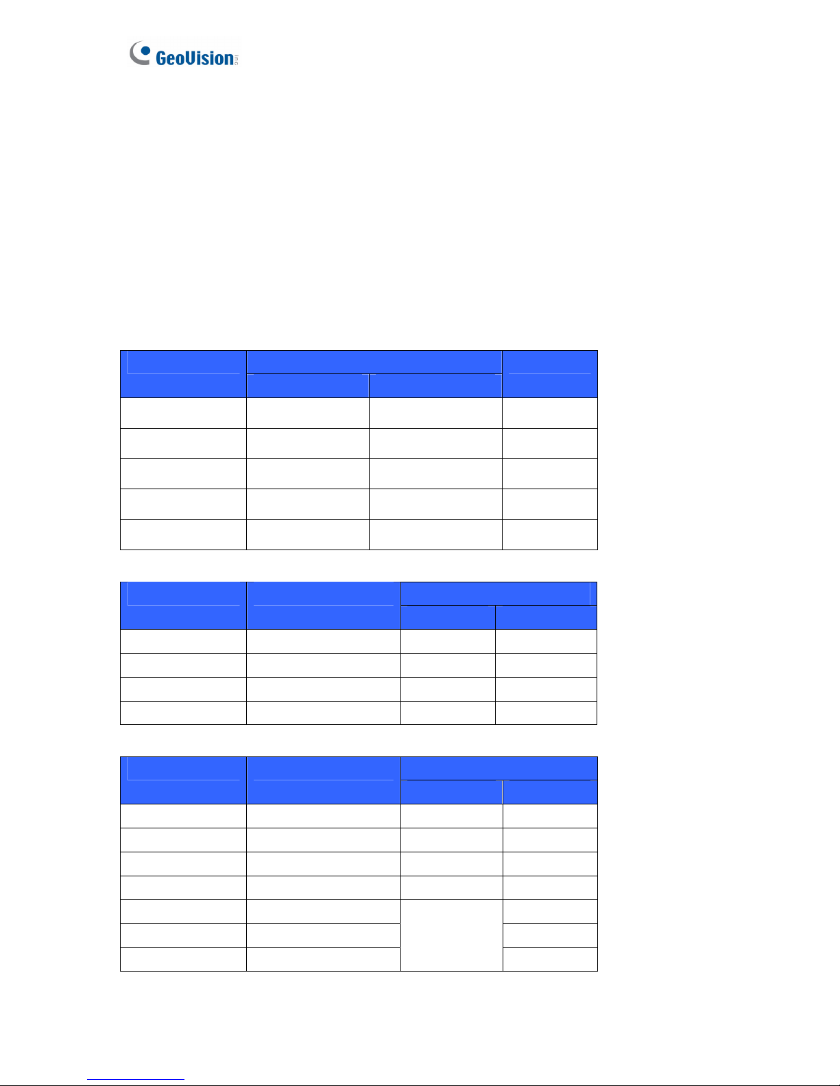
Below are the total frame rates GV-Tower DVR/NVR System can support with CPU usage of
approximately 70% to ensure performance and stability. You could connect up to 32 cameras
to the system. See the below charts to calculate frame rate for connected IP cameras.
For instance, if you connect 10 units of GV Fisheye 1.3 MP cameras to the system supporting
CPU Intel Core i3 Processor, you will receive 12 fps for each channel (120 fps / 10 units = 12
fps).
For GV IP Cameras
Dual Streams Video Resolution
Stream 1 (H.264) Stream 2 (MPEG4)
Total Fps
D1 704 x 480 352 x 240 960 fps
1.3 MP 1280 x 1024 320 x 256 960 fps
2 MP 1920 x 1080 448 x 252 960 fps
3 MP 2048 x 1536 320 x 240 640 fps
5 MP 2560 x 1920 320 x 240 320 fps
For GV Fisheye Cameras (De-warping)
Total FPS Video Resolution Single Stream (H.264)
Intel Core i3 Intel Core i5
1.3 MP 1280 x 1024 120 fps 180 fps
2 MP 1440 x 1376 105 fps 120 fps
4 MP 2048 x 1944 45 fps 60 fps
5 MP 2560 x 1920 30 fps 40 fps
For Third-Party IP Cameras (GPU Decode)
Total FPS Video Resolution Single Stream (H.264)
Intel Core i3 Intel Core i5
VGA 640 x 480 960 fps 960 fps
1 MP 1280 x 720 570 fps 960 fps
1.3 MP 1280 x 1024 570 fps 960 fps
2 MP 1920 x 1080 390 fps 660 fps
3 MP 2048 x 1536 500 fps
4 MP 2048 x 1944 360 fps
5 MP 2560 x 1920
Not supported
300 fps
56
Page 63

Appendix
57
C. Supported IP Devices
This list provides the supported IP device brands. For detailed information on the supported IP
devices, refer to Supported IP Camera List on GeoVision’s Website:
http://www.geovision.com.tw/english/4_21.asp
GeoVision
ACTi
Arecont Vision
AXIS
Bosch
Canon
CNB
D-Link
Etrovision
Hikvision
HUNT
IQinVision
JVC
MOBOTIX
Panasonic
Pelco
Samsung
Sanyo
SONY
UDP
Verint
VIVOTEK
Page 64

Warranty Policy
GeoVision, Inc. (“GeoVision”) provides types of Limited Warranty for products. Please see
Limited Warranty Table on main page of official website (www.geovision.com.tw
) for detail
information.
All aforementioned products, EXCLUDE ALL SOFTWARE AND SOME PACKAGED
ACCESSORIES LISTED IN LIMITED WARRANTY TABLE, (hereinafter called “Products”)
will be free from defects in materials/workmanship during the terms of these Limited
Warranties (“Limited Warranties”) from the date of purchase. These Limited Warranties parts
and labor warranty are applicable to Products purchased via authorized distribution and sales
channels.
If a defect arises and a valid claim is received by GeoVision within Limited Warranties Period,
at its option, GeoVision will (1) repair Products at no charge, using new or refurbished
replacement parts, or (2) exchange Products with a Product that is new or which has been
manufactured from new or serviceable used parts and is at least functionally equivalent to the
original Products.
GeoVision warrants replacement parts or repairs for thirty (30) days from the date of
GeoVision shipment or for the remainder of Limited Warranties Period, whichever provides
longer coverage for you. When a Product or part is exchanged, any replacement item
becomes your property and the replaced item becomes GeoVision’s property.
It is customer’s sole responsibility and requirement to prove these Products are under
warranty (by submit your sales invoice and bar code), otherwise GeoVision will determine
these Products’ warranties period at its option. GeoVision reserves the right, at its sole
discretion and any time, to modify and adjust the scope and content of Products and its
warranty without prior notice, however, any modification and adjustment thereafter will not
affect or interrupt any rights belonging to Products you purchased already.
Limitations of Warranties
Limited Warranties apply only to Products manufactured by or for GeoVision that can be
identified by the "GeoVision" trademark, trade name, or logo affixed to them. Limited
Warranties do not apply to any non-GeoVision products including counterfeited products.
GeoVision is not liable for any damage to or loss of any profit, programs, data, or other
information stored on any media, or any non-GeoVision products or part not covered by these
warranties. Recovery and reinstallation of system and application software and user data are
not covered under Limited Warranties. Limited Warranties do not apply if:
a) Products have been subjected to abnormal use, improper storage, unauthorized
modifications, unauthorized repair, misuse, neglect, abuse, accident, alternation, removal
58
Page 65

Warranty Policy
of any stickers or labels on the hardware, improper hardware/software installations, or
other acts that are not the faults of GeoVision, including damage caused by shipping;
b) Products have been damaged from exposure under circumstances which is over
weatherproof specification of the product, an Act of God, or improper use of any electrical
source, or the connection to other products not recommended for interconnection by
GeoVision;
c) Products have defects or damage caused due to computer virus attack, internet or
technical issues;
d) Products serial number have been removed, defaced or altered; or
e) Products have been sold by an unauthorized distributor or retailer.
f) The GV system case has been opened.
g) Products have been interoperated with any non-GeoVision products which GeoVision does
not approve the compatibility.
Disclaimer of Warranties
EXCEPT AS SPECIFIED IN THESE WARRANTIES, ALL EXPRESS OR IMPLIED
CONDITIONS, REPRESENTATIONS, AND WARRANTIES INCLUDING, WITHOUT
LIMITATION, ANY IMPLIED WARRANTIES OR CONDITION OF MERCHANTABILITY,
FITNESS FOR A PARTICULAR PURPOSE, NON-INFRINGEMENT, SATISFACTORY
QUALITY, NON-INTERFERENCE, ACCURACY OF INFORMATIONAL CONTENT, OR
ARISING FROM A COURSE OF DEALING, LAW, OR TRADE PRACTICE, ARE HEREBY
EXCLUDED TO THE EXTENT ALLOWED BY APPLICABLE LAW AND ARE EXPRESSLY
DISCLAIMED BY GEOVISION. TO THE EXTENT IMPLIED WARRANTIES CANNOT BE
EXCLUDED, SUCH WARRANTIES ARE LIMITED IN DURATION TO THE EXPRESS
WARRANTIES PERIOD. BECAUSE SOME STATES OR JURISDICTIONS DO NOT ALLOW
LIMITATIONS ON HOW LONG IMPLIED WARRANTIES LASTS, THE ABOVE LIMITATION
MAY NOT APPLY. THESE WARRANTIES GIVE CUSTOMERS SPECIFIC LEGAL RIGHTS,
AND CUSTOMER MAY ALSO HAVE OTHER RIGHTS WHICH VARY FROM JURISDICTION
TO JURISDICTION. THIS DISCLAIMER AND EXCLUSION SHALL APPLY EVEN IF THE
EXPRESS WARRANTIES SET FORTH ABOVE FAILS OF ITS ESSENTIAL PURPOSE.
GEOVISION MAKES NO WARRANTIES AND LIABILITIES, EXPRESS OR IMPLIED, WITH
RESPECT TO NON-GEOVISION PRODUCTS OR THEIR INTEROPERATION WITH THE
PRODUCTS AND DISCLAIM ANY IMPLIED WARRANTIES OF MERCHANTABILITY,
COMPATIBILITY, FITNESS FOR A PARTICULAR USE, OR INTEROPERATION BETWEEN
PRODUCTS AND NON-GEOVISION PRODUCTS. GEOVISION SHALL NOT BE LIABLE
FOR INCLUDING BUT NOT LIMITED TO ANY DATA LOST, LOSS AND DAMAGE, DIRECT
OR INDIRECT, FOR ANY INTEROPERATION BETWEEN THE PRODUCTS AND
NON-GEOVISION PRODUCTS.
59
Page 66

60
Limitation of Liability
Regardless whether any remedy set forth herein fails of its essential purpose or otherwise, in
no event will GeoVision or its suppliers be liable for any lost revenue, profit or lost or damaged
data, business interruption, loss of capital, or for special, indirect, consequential, incidental, or
punitive damages however caused and regardless of the theory of liability or whether arising
out of the use or inability to use the GeoVision Products or otherwise and even if GeoVision
has been advised of the possibility of such damages. In no event shall GeoVision's liability to
customer, whether in contract, tort (including negligence), breach of warranty, or otherwise,
exceed the price paid by customer for the Software that gave rise to the claim or if the
Software is part of another Products, the price paid for such other Products. Because some
states or jurisdictions do not allow limitation or exclusion of consequential or incidental
damages, the above limitation may not apply to you. In no event shall GeoVision’s total liability
to you for all damages (other than as may be required by applicable law in cases involving
personal injury) exceed the amount of two hundred dollars (U.S. $200.00). The foregoing
limitations will apply even if the above stated remedy fails of its essential purpose.
Customer agrees that the limitations of liability and disclaimers set forth herein will apply
regardless of whether customer has accepted any other Products or service delivered by
GeoVision. Customer acknowledges and agrees that GeoVision has set its prices in reliance
upon the disclaimers of warranties and the limitations of liability set forth herein, that the same
reflect an allocation of risk between the parties, and that the same form an essential basis of
the bargain between the parties.
These Warranties shall be governed by and construed in accordance with the laws of Taiwan,
Republic of China and United State, without reference to or application of choice of law rules
or principles. The United Nations Convention on the International Sale of Goods shall not
apply. If any portion hereof is found to be void or unenforceable, the remaining provisions
shall remain in full force and effect.
FOR AUSTRALIA ONLY:
Our products come with guarantees that cannot be excluded under the Australian Consumer
Law. You are entitled to a replacement or refund for a major failure and for compensation for
any other reasonably foreseeable loss or damage. You are also entitled to have the products
repaired or replaced if the products fail to be of acceptable quality and the failure does not
amount to a major failure. Please visit www.accc.gov.au
for more information. GeoVision Inc.
9F, No.246, Sec.1, Neihu Rd., Neihu District Taipei 114, Taiwan R.O.C. Tel: 886-2-8797-8376
Email: [email protected]
GeoVision Inc. Warranty Policy last updated on August 14, 2013.
Page 67

Warranty Requirements
Warranty Requirements
To validate your purchase, you shall complete the online Product Registration within 30 days
from the date of purchase at http://www.geovision.com.tw/english/4_6.asp
. Or click
GeoVision Online Registration in My Favorite for a direct link.
If you fail to complete the Product Registration, the warranty period will start from the date of
shipment.
Before you return the product
Some problems you experience may be related to software or the operating system. It is
important to investigate other sources of assistance first. Before returning the product, try the
following:
1. Review troubleshooting sections in the documentation for software and peripheral
devices.
2. Try rebuilding the operating system and GV-System by using the Recovery DVD.
3. Consult your dealer. They are your best sources for current information and support. Or
you can call or email GeoVision offshore offices for assistance.
When you call or e-mail, please inform us the following:
z Model name
z Bar Code
z Details of the defect or problem
z Attempted solutions
z Your contact information
z Reseller’s contact information
4. If you find it is the software problem, please check our website or your dealer for software
updates.
61
Page 68

62
Obtaining Warranty Service
If you are still unable to solve the problem and suspect that it is hardware related, follow
these:
1. Send an e-mail to GeoVision to start Return Merchandise Authorization (RMA) process.
E-Mail: [email protected]
2. Securely pack the product in its original carton using the original packing material, or in
equivalent packaging.
3. The product shall be returned to GeoVision, Taiwan at your expense for shipping and
insurance costs.
BEFORE YOU DELIVER YOUR GV-TOWER DVR/NVR SYSTEM FOR WARRANTY
SERVICE, IT IS YOUR RESPONSIBILITY TO BACK UP YOUR DATA. YOU WILL BE
RESPONSIBLE FOR REINSTALLING ALL DATA, SETTINGS AND PASSWORDS. DATA
RECOVERY IS NOT INCLUDED IN THE WARRANTY SERVICE AND GEOVISION IS NOT
RESPONSIBLE FOR DATA THAT MAY BE LOST OR DAMAGED DURING TRANSIT OR A
REPAIR.
Page 69
Warranty Form
63
Warranty Form
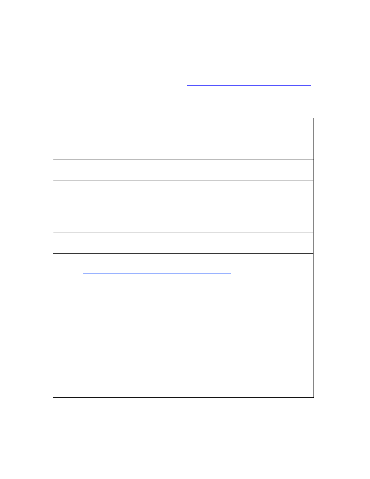
Thank you for purchasing the GV-Tower DVR/NVR System. To help us validate your purchase
and better serve you in the future, please go to http://www.geovision.com.tw/english/4_6.asp
or click GeoVision Online Registration in My Favorite for a direct link to register online
within 30 days from the date of purchase. Please keep this copy for your records.
Name: First (given) Surname (family name)
Company Name (only if the product is owned by company):
Mailing Address:
City/Town: Province/State:
Country: Postal Code:
Telephone: (O) (H)
Fax:
E-Mail:
Date of Purchase: (e.g. 16-APR-2012)
Product: Please check the model and its items you purchased.
Model
GV–Tower DVR System GV–Tower NVR System
The system with third-party IP devices
1 Channel 2 Channels 4 Channels 6 Channels
8 Channels 10 Channels 12 Channels 14 Channels
16 Channels 18 Channels 20 Channels 22 Channels
24 Channels 26 Channels 28 Channels 30 Channels
32 Channels
Page 70
64
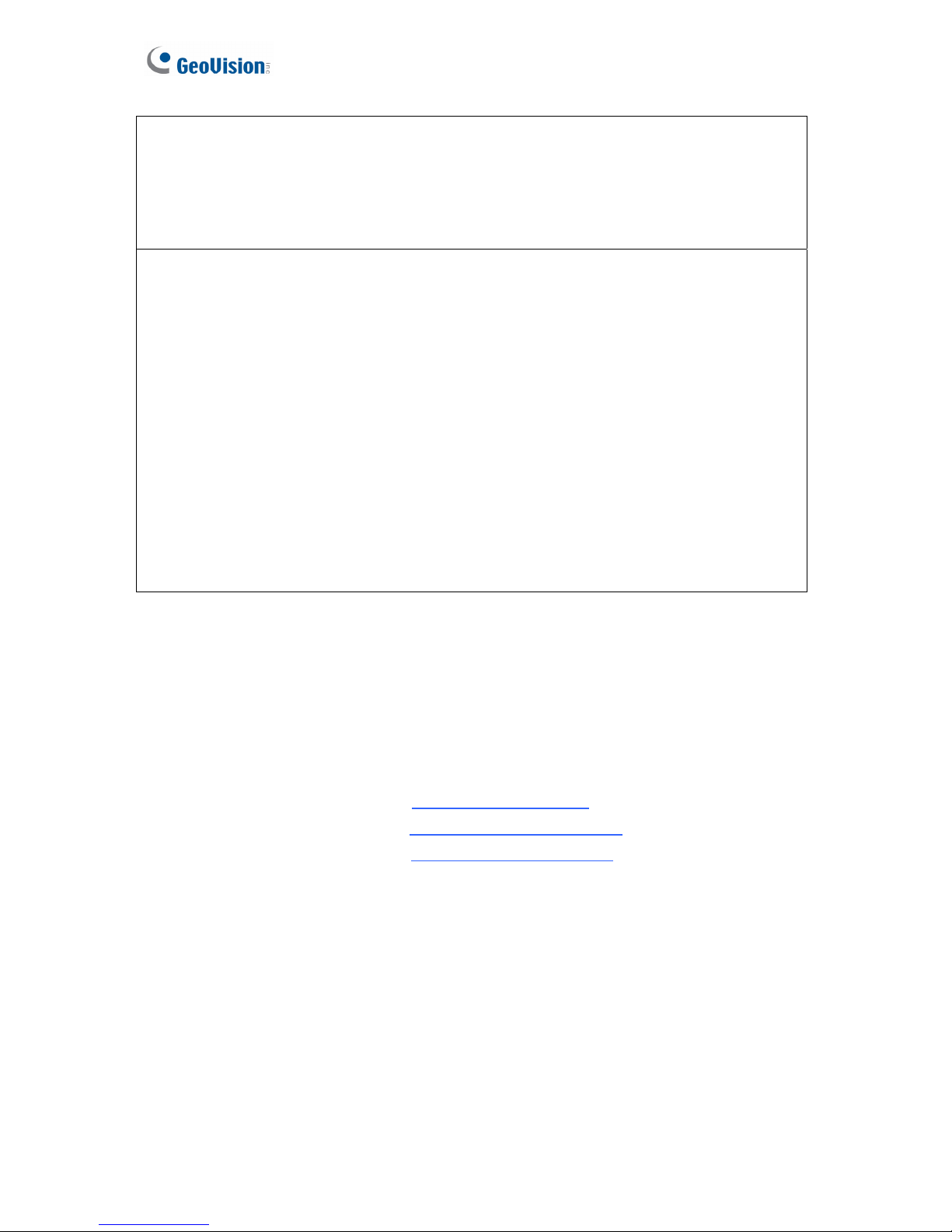
Bar Code:
Shipment Date:
GeoVision, Inc.
9F, No. 246, Sec. 1, Neihu Rd.,
Neihu District, Taipei, Taiwan
Tel: +886-2-8797-8377
Fax: +886-2-8797-8335
Email: [email protected]
http://www.geovision.com.tw
 Loading...