

Page 1
Quick Start Guide
GV-Panoramic PTZ Camera
Before attempting to connect or operate this product,
please read these instructions carefully and save this manual for future use.
PPTZ-QG-A
Page 2
© 2018 GeoVision, Inc. All rights reserved.
Under the copyright laws, this manual may not be copied, in whole or in part,
without the written consent of GeoVision.
Every effort has been made to ensure that the information in this manual is
accurate. GeoVision, Inc. makes no expressed or implied warranty of any kind
and assumes no responsibility for errors or omissions. No liability is assumed
for incidental or consequential damages arising from the use of the information
or products contained herein. Features and specifications are subject to
change without notice.
Note: No memory card slot or local storage function for Argentina.
GeoVision, Inc.
9F, No. 246, Sec. 1, Neihu Rd.,
Neihu District, Taipei, Taiwan
Tel: +886-2-8797-8377
Fax: +886-2-8797-8335
http://www.geovision.com.tw
Trademarks used in this manual: GeoVision, the GeoVision logo and GV
series products are trademarks of GeoVision, Inc. Windows is the registered
trademark of Microsoft Corporation.
March 2018
Page 3

Contents
Note for Connecting to GV-VMS ..........................................................ii
Note for Recording...............................................................................iii
Note for Installing Camera................................................................... iv
Note for Silica Gel Bags........................................................................v
Optional Accessories .......................................................................... vi
1. Introduction ....................................................................................1
1.1 Packing List ......................................................................................................... 2
GV-PPTZ7300..................................................................................................... 2
GV-PPTZ14021 / 14031...................................................................................... 3
1.2 Overview.............................................................................................................. 4
GV-PPTZ7300..................................................................................................... 4
GV-PPTZ14021 / PPTZ14031............................................................................. 5
2. Installation ......................................................................................6
GV-PPTZ7300..................................................................................................... 6
GV-PPTZ14021 / PPTZ14031............................................................................12
3. Connecting the Camera ...............................................................18
4. Accessing GV-Panoramic PTZ Camera ...................................... 20
4.1 Web Browser ......................................................................................................20
GV-PPTZ7300....................................................................................................20
GV-PPTZ14021 / PPTZ14031............................................................................20
4.2 Checking the Dynamic IP Address......................................................................22
4.3 Configuring the IP Address .................................................................................24
i
Page 4

5. The Integrated Web Interface.......................................................26
5.1 Fisheye View ......................................................................................................28
5.2 Speed Dome View ..............................................................................................29
6. Upgrading System Firmware ....................................................... 30
7. Restoring to Factory Default........................................................31
7.1 Using the Web Interface .....................................................................................31
7.2 Directlly on the Camera ......................................................................................32
ii
Page 5

Note for Connecting to GV-VMS
The GV-Panoramic PTZ Camera is designed to work with GV-VMS, a video management
system. Note the following when the camera is connected to GV-VMS:
1. By default, the images are recorded to the memory card inserted in the GV- Panoramic
PTZ Camera.
2. Once the camera is connected to the GV-VMS, the resolution set on the GV-VMS will
override the resolution set on the camera’s Web interface. You can only change the
resolution settings through the Web interface when the connection to the GV-VMS is
interrupted.
ii
i
Page 6

Note for Recording
1. By default, the images are recorded to the memory cards inserted in the GV-Panoramic
PTZ Camera. Make sure the Write recording data into local storage option is enabled
See 4.1.1 Video Settings, Chapter 4, GV-Panoramic PTZ Camera User’s Manual. If this
option is disabled, the camera will stop recording to the memory card while the live view is
accessed through Web browsers or other applications.
2. Mind the following when using a memory card for recording:
Recorded data on the memory card can be damaged or lost if the data are accessed
while the camera is under physical shock, power interruption, memory card
detachment or when the memory card reaches the end of its lifespan. No guarantee is
provided for such causes.
The stored data can be lost if the memory card is not accessed for a long period of
time. Back up your data periodically if you seldom access the memory card.
Memory cards are expendable and their durability varies according to the conditions
of the installed site and how they are used. Back up your data regularly and replace
the memory card annually.
To avoid power outage, it is highly recommended to apply a battery backup (UPS).
Replace the memory card when its read/write speed is lower than 6 MB/s or when the
memory card is frequently undetected by the camera.
It is recommended to use Micro SD card of MLC NAND flash, Class 10 for optimal
performance.
iv
Page 7
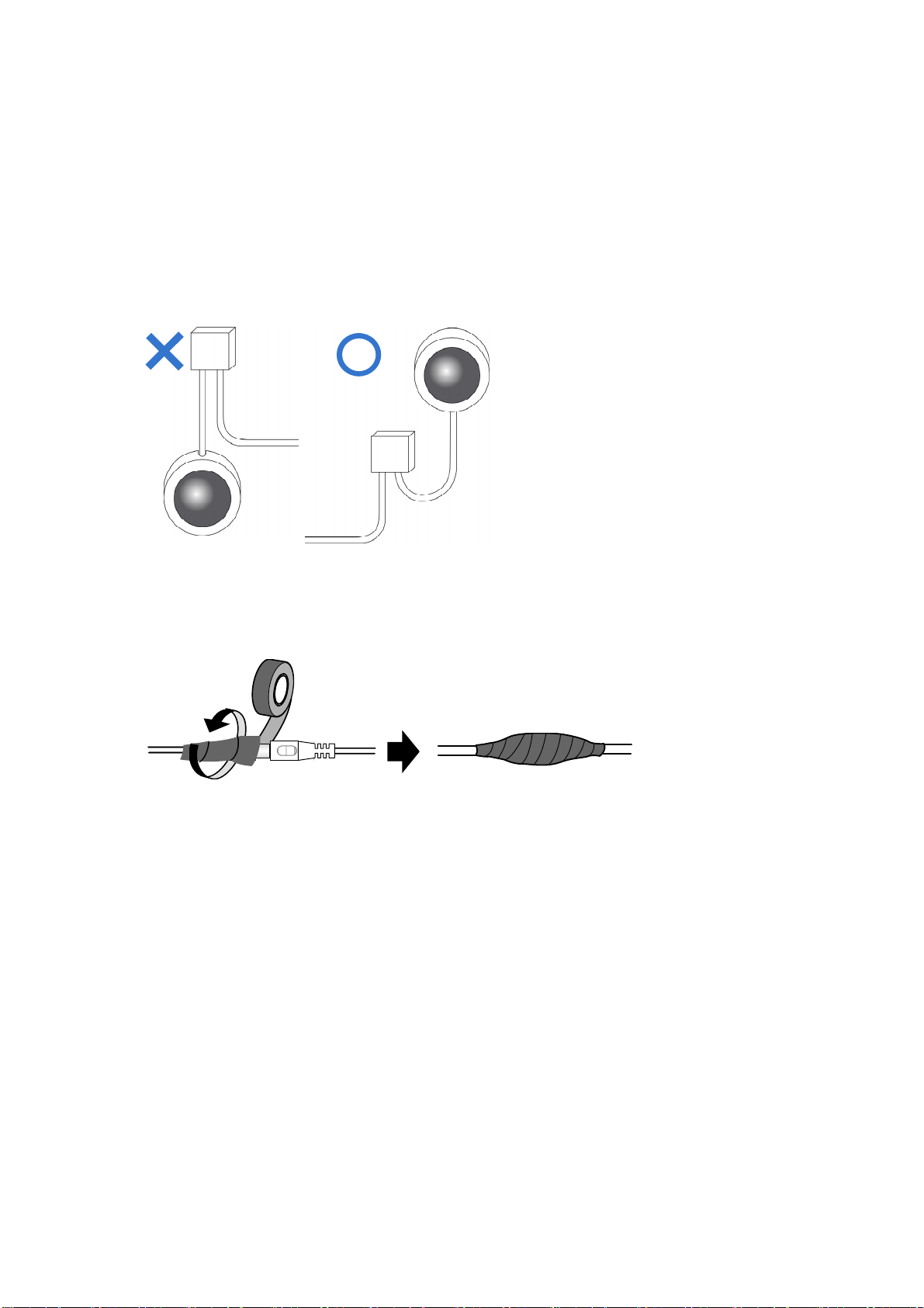
Note for Installing Camera
When installing GV-Panoramic PTZ Camera, be sure that:
1. The camera is set up above the junction box to prevent water from entering the camera
along the cables.
2. Any PoE, power, audio and I/O cables are waterproofed using waterproof silicon rubber
or the like.
3. The screws are tightened and the cover is in place after opening the camera cover.
v
Page 8

Note for Silica Gel Bags
1. The silica gel bag loses its effectiveness when the dry camera is opened. To prevent the
lens from fogging up, use the supplied adhesive tape and replace the silica gel bag every
time you open the camera, and conceal the gel bag in the camera within 2 minutes of
exposing to open air.
2. When the camera is shipped, a silica gel bag will be included inside the camera. For
first-time users, replace the silica gel bag prior to the installation to avoid foggy live view.
vi
Page 9

Optional Accessories
Optional devices can expand the capabilities and versatility of your camera. Contact our sales
representatives for more information.
Name Details
GV-PA901
Power over Ethernet (PoE)
Adapter
GV-Mount Accessories
GV-POE Switch
Power Adapter
The GV-PA901 is a Power over Ethernet (PoE) adapter
designed to provide power to the IP device through a single
Ethernet cable to the GV-PPTZ camera.
The GV-Mount Accessories provides a comprehensive lineup
of accessories for installation on ceiling, wall and pole. For
details, see GV-Mount Accessories Installation Guide online.
The GV-POE Switch is designed to provide power along with
network connection for IP devices. The GV-POE Switch is
available in various models with different numbers and types
of ports.
Contact our sales representatives for the countries and areas
supported.
vii
Page 10

1. Introduction
elcome to the GV-Panoramic PTZ Camera Quick Start Guide. In the following sections, you
W
will learn the basic installations and configurations of GV-Panoramic PTZ Camera. For a
detailed user manual, see the GV-Panoramic PTZ Camera User’s Manual from our website:
http://www.geovision.com.tw/download/product/
.
1
Page 11
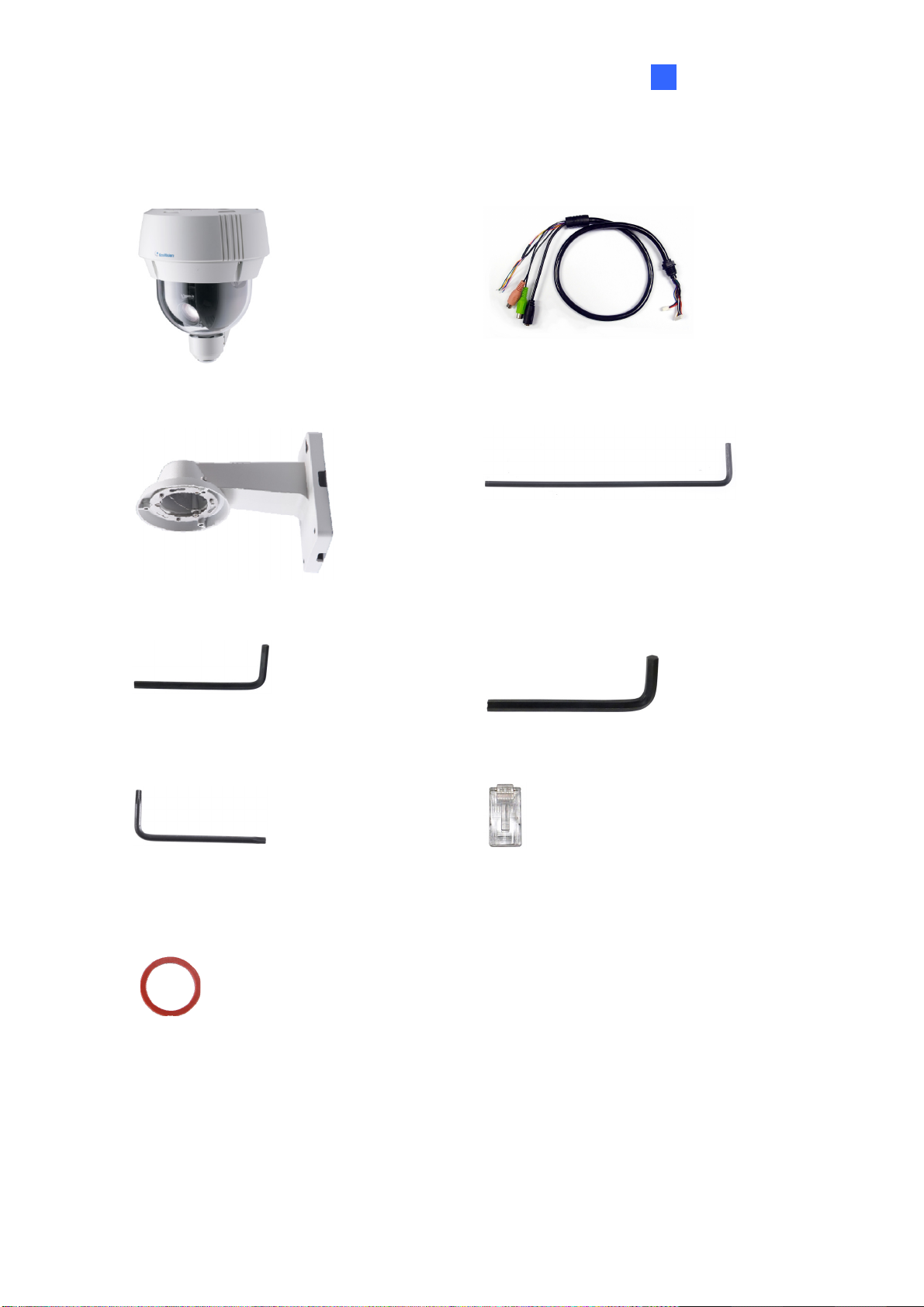
1.1 Packing List
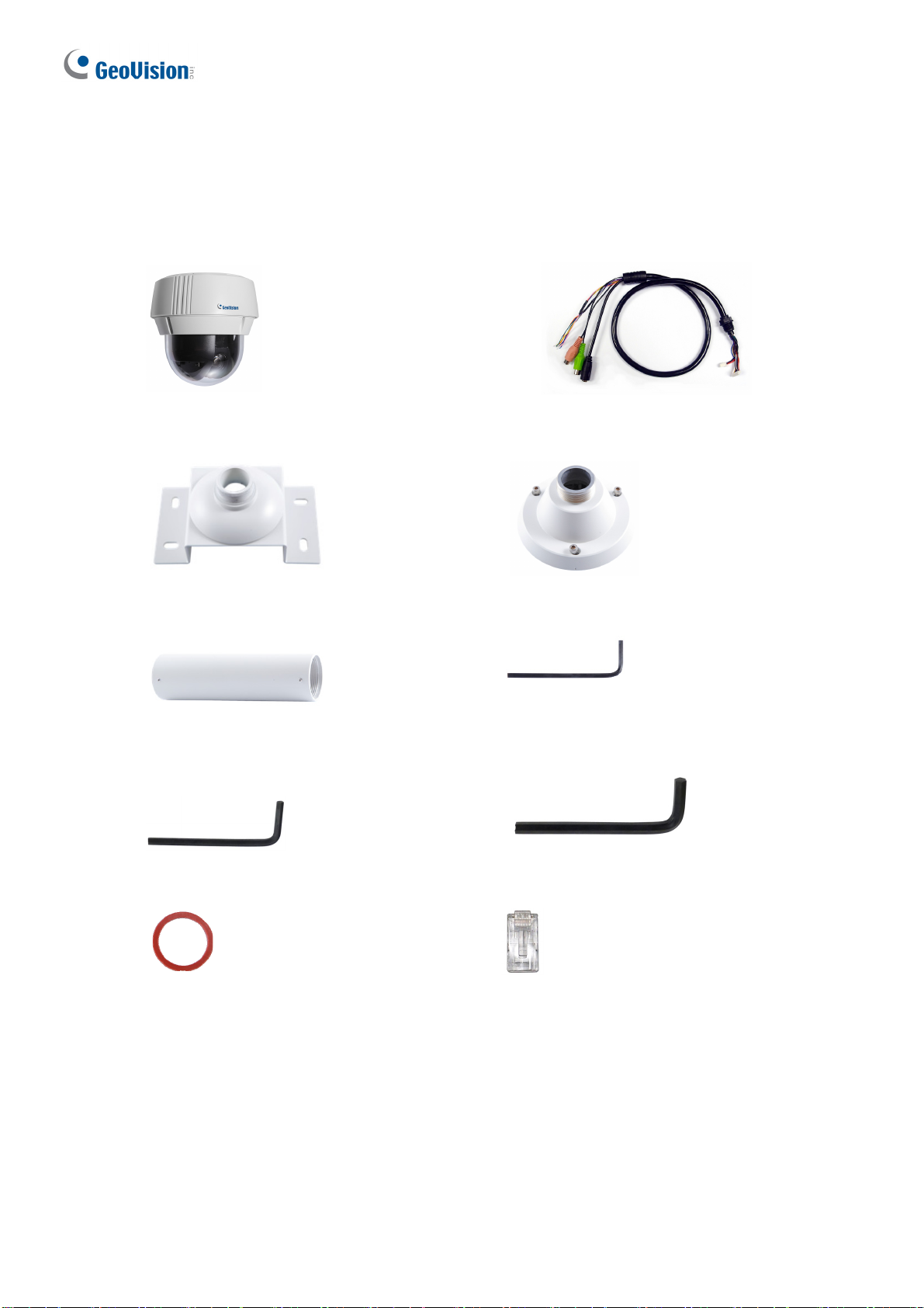
GV-PPTZ7300
Panoramic PTZ Camera
Mounting Bracket
Tube
Data Cable
Mounting Cap
2 mm Hex Key
3 mm Hex Key
Rubber ring
Download Guide
Desiccant Pack x 2
Warranty Card
5 mm Hex Key
RJ-45 Connector
2
Page 12
GV-PPTZ14021 / 14031
Introduction
1
Panoramic PTZ Camera
Pendant Tube
4 mm Hex Key
Data Cable
3 mm Hex Key
5 mm Hex Key
Torx Wrench
Rubber ring
Download Guide
Desiccant Pack x 2
Warranty Card
RJ-45 Connector
3
Page 13
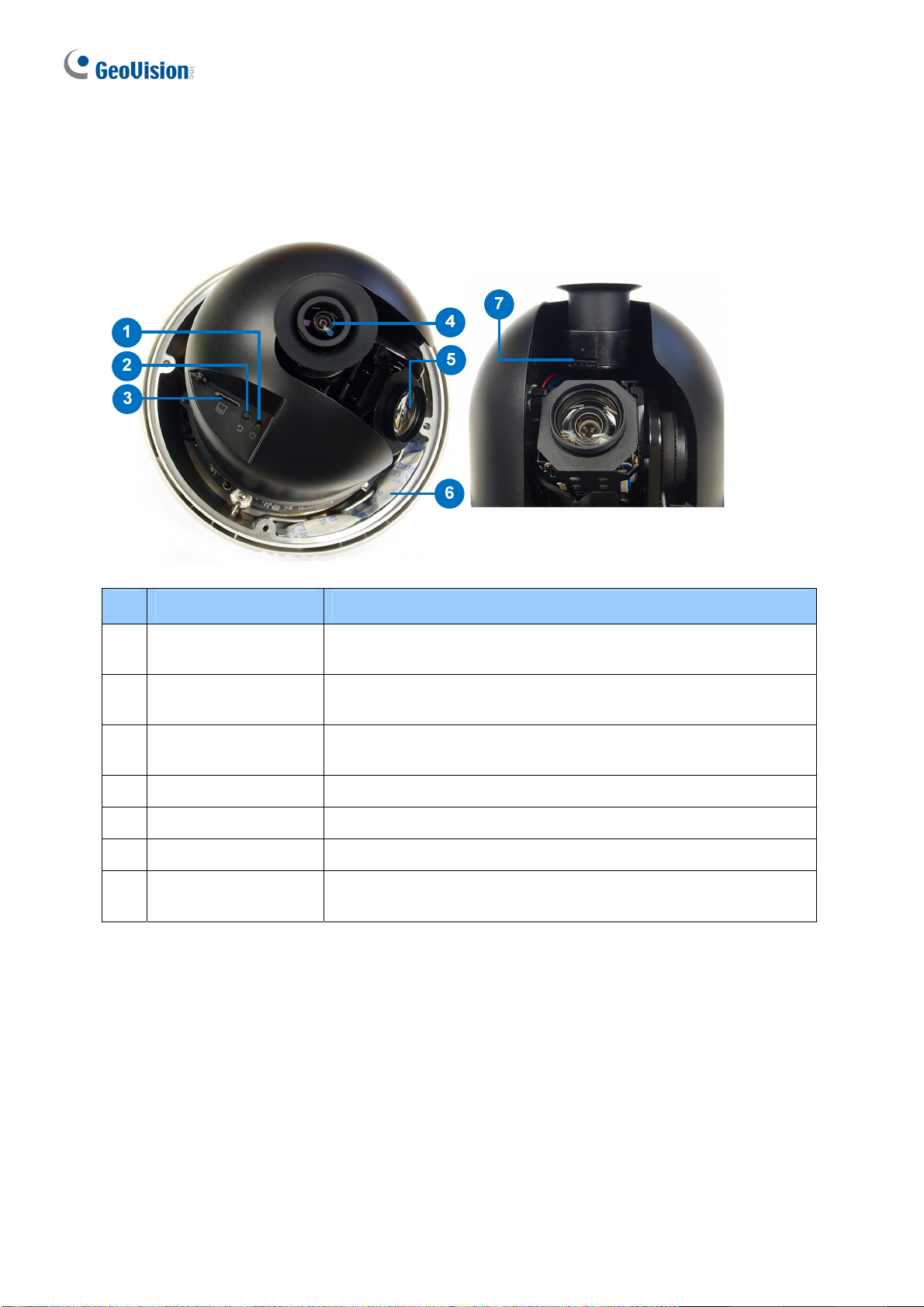
1.2 Overview
GV-PPTZ7300
No. Name Function
1 Status LED
2 Default Button
Speed Dome SD
3
Card Slot
4 Fisheye Lens Receives image inputs.
5 Speed Dome Lens Receives image inputs.
6 Desiccant Pack Keeps the camera housing dry.
Fisheye SD Card
7
Slot
Flashes when the camera is powering on and loading default
settings.
Resets all configurations to default factory settings. See
Chapter 7 Restoring to Factory Default.
Inserts a micro SD card (SD/SDHC, version 2.0, Class 10) to
store recording data from the speed dome.
Inserts a micro SD card (SD/SDHC, version 2.0, Class 10) to
store recording data from the fisheye camera.
4
Page 14

GV-PPTZ14021 / PPTZ14031
1
Introduction
1
4
5
2
3
No. Name Function
1. Fisheye Lens Receives image input.
2. Speed Dome Lens Receives image input.
3. Fisheye SD Card Slot
Inserts a micro SD card (SD/SDHC/SDXC/UHS-I, Class
10) to store recording data from the fisheye camera.
6
7
4.
5. Default Button
6. Status LED
7. Desiccant Pack Keeps the camera housing dry.
Speed Dome SD Card
Slot
Inserts a SD card (SD/SDHC/SDXC/UHS-I, Class 10) to
store recording data from the speed dome.
Resets all configurations to default factory settings. See
Chapter 7 Restoring to Factory Default.
Flashes when the camera is booting up and loading
default settings.
5
Page 15

2. Installation
GV-Panoramic PTZ Camera can be mounted on the ceiling or on the wall using the supplied
Straight Tube Mount (GV-PPTZ7300) / Pendant Tube Mount (GV-PPTZ14021/PPTZ14031).
Make sure the ceiling has enough strength to support the camera and the mount.
GV-PPTZ7300
Required items:
Screws for ceiling x 4 (Self-prepared)
Optionally extend with:
GV-Mount702
Recommended Installation Height
It is recommended to install the camera at a height of 6.5 m (21 ft), which allows the camera to
have a monitor radius of up to 25 m (82 ft).
Installation Height Max. Horizontal Distance (Radius)
6.5 m (21 ft) 25 m (82 ft)
5 m (16 ft) 20 m (66 ft)
4 m (13 ft) 17 m (56 ft)
3 m (10 ft) 13 m (43 ft)
6
Page 16

Installation
2
1.
Insert the desiccants to the camera.
A. Remove the camera cover using the 3 mm hex key.
B. Insert your SD cards into the SD card slots for the fisheye camera and the speed dome.
C. Insert one set of desiccant packs to the indicated place.
IMPORTANT: Be sure the desiccants are concealed in the camera within 2 minutes of
opening the desiccant packs.
D. Secure the camera cover with the 3 mm hex key. Make sure the first two screws to be
tightened are diagonal to each other.
7
Page 17

2. Assemble the supplied mounting bracket, tube and mounting cap by rotating the parts
together.
3. Make sure the tubes are properly screwed. Tighten the screws using the 2 mm hex key.
4. Connect the cables to the camera.
A.
At the back of the camera, remove the cap and use the 3 mm hex key to remove the
mounting plate.
8
Page 18

Installation
2
B.
Slide the cap and components through the Ethernet cable as shown below, and attach the
supplied RJ-45 connector to the cable.
C. Insert the Ethernet cable to the LAN port, move the cap and the components toward the LAN
port, and secure the cap tightly.
Slip the rubber ring on the data cable and then pass the pin connectors of the data cable
D.
through the mounting plate.
The rubber ring
The Data Cable
9
Page 19

E. Fasten the data cable with the mounting plate and the rubber ring.
F. Insert the pin connectors of the data cable to the indicated area.
G. Secure the mounting plate with the 3 mm hex key.
5. Thread the cables through the tube.
6. Secure the camera with the mounting cap.
A
. Secure the safety lock.
10
Page 20

2
B.
Push the rivets into the holes on the mounting cap and rotate clockwise to lock the position.
C. Rotate the camera onto the mounting cap and secure using the 5 mm hex key.
Installation
7.
Secure the assembled camera to the ceiling with 4 self-prepared screws.
11
Page 21

GV-PPTZ14021 / PPTZ14031
Required items:
Screws for ceiling x 4 (Self-prepared)
Recommended Installation Height
ecommended to install the camera at a height of 6.5 m (21 ft), which allows the camera to
It is r
have a monitor radius of up to 25 m (82 ft).
12
Page 22

1.
Insert the desiccants to the camera.
A. Loosen the screws at the bottom of the fisheye arm.
Installation
2
WARNING: Do not remove the screw indicated in the picture below, or the fisheye lens will
fall.
13
Page 23

B. Adjust the position of the fisheye arm.
C.
Unscrew the camera cover using the 3 mm hex key.
14
Page 24

Installation
2
D.
Insert your SD cards into the SD card slots for the fisheye camera and the speed dome.
Speed Dome
Memory Card
Slot
Fisheye Memory
Card Slo t
E. Insert one set of desiccant packs to the indicated area.
IMPORTANT: Be sure the desiccants are concealed in the camera within 2 minutes of
opening the desiccant packs.
. Secure the camera cover with the 3 mm hex key. Make sure the first two screws to be
F
tightened are diagonal to each other.
15
Page 25

2. Connect the cables to the camera.
A. Thread the Ethernet cable and the data cable through the pendant tube.
See Step 4-A – Step 4-G, GV-PPTZ7300 earlier in this chapter for the same setup.
B.
3. Assemble the camera with the pendant tube.
A. Secure the safety lock.
B.
Push the rivets into the holes on the pendant tube and rotate clockwise to lock the position.
16
Page 26

C. Tighten the screws with the supplied hex key.
Secure the pendant tube to the wall with self-prepared screws.
D.
2
stallation
In
17
Page 27

3. Connecting the Camera
The GV-Panoramic PTZ Camera comes with a data cable that allows you to connect to the
power adapter, microphone, speaker, and any I/O devices. Follow the steps below to connect
the camera.
1. Connect Power using one of the following methods:
Connect the Power Adapter to the camera.
Use the Power over Ethernet (PoE) function to supply power over the network cable. See
Connecting the GV-PA901 PoE Adapter.
2. Connect a standard network cable to the Ethernet cable of the camera.
3. Optionally connect I/O devices, speaker and microphone to the camera. You can connect
up to 4 alarm input and 1 output devices. See I/O Wire Definition.
Note:
1. The Power Adapter is an optional device.
2. Optional GV-PA901 PoE Adapter is required for applying the PoE function.
18
Page 28

I/
O Wire Definition
No. Wire Definition
1 Orange Alarm In 1
2 Yellow Alarm In 2
3 Green Alarm In 3
4 Blue Alarm In 4
5 Pink Ground
6 Purple Alarm Out
7 White Alarm Out_Open
Connecting the Camera
3
8 Gray Alarm Out_Close
Connecting the GV-PA901 PoE Adapter
1. Connect one end of an Ethernet cable to the LAN 10 / 100 Port on the GV-PA901 and
the other end to a Hub / Router.
2. Connect one end of an Ethernet cable to the PoE 10 / 100 port on the GV-PA901, and
the other end to the GV-PPTZ camera.
3. Connect the GV-PA901 Power Adapter to the power outlet.
19
Page 29

4. Accessing GV-Panoramic PTZ Camera
4.1 Web Browser
Once installed, your camera is accessible over the network. Make sure your network
connection is active, and the following requirements are met.
GV-PPTZ7300
OS 64-bit Windows 7 / 8 / 8.1 / 10 / Server 2008 R2 / Server 2012 R2
GV-VMS V15.10.1.0 with patch files or later versions
Browser Internet Explorer 7.x or later
Firefox
Google Chrome
Safari
GV-PPTZ14021 / PPTZ14031
OS 64-bit Windows 7 / 8 / 8.1 / 10 / Server 2008 R2 / Server 2012 R2
GV-VMS V16.11.0.0 with patch files or later versions
Browser Internet Explorer 8.x or later
Firefox
Google Chrome
Safari
20
Page 30

Accessing GV-Panoramic PTZ Camera
4
ote:
N
1. If you are using Microsoft Internet Explorer 8.0 or later, additional settings are required.
Refer to Settings for Internet Explorer 8 or later, Appendix A, GV-Panoramic PTZ
Camera User’s Manual.
2. When using non-IE browsers,
a. Certain functions are not supported by non-IE browsers. To see the functions
available on live view windows using non-IE browsers, see Figure 3-13,
GV-Panoramic PTZ Camera User’s Manual.
b. RTSP streaming must be enabled. By default, RTSP streaming is enabled. See 4.3.8
RTSP/ONVIF, GV-Panoramic PTZ Camera User’s Manual for the details on RTSP
settings.
c. Only MJPEG codec is supported.
21
Page 31

4.2 Checking the Dynamic IP Address
By default, when GV-Panoramic PTZ camera is connected to LAN with a DHCP server, it is
automatically assigned with a dynamic IP address. Follow the steps below to look up its IP
address.
1. Download and install the GV-IP Device Utility program from the GeoVision website:
http://www.geovision.com.tw/download/product/
.
Note: The PC installed with GV-IP Device Utility must be under the same LAN as the
camera you wish to configure.
2. On the GV-IP Utility window, click the
button to search for the IP devices connected
in the same LAN. Click the Name or Mac Address column to sort. You will see both the
fisheye camera and the speed dome being listed as GV-PPTZ – FE and GV-PPTZ – SD.
3. Click on the IP address of the fisheye camera and select Web Page.
22
Page 32

Accessing GV-Panoramic PTZ Camera
4
4.
The login page of the integrated interface appears. Type the default ID and password
admin and click Apply.
23
Page 33

4.3 Configuring the IP Address
By default, GV-Panoramic PTZ Camera, connected to LAN without a DHCP server, is
assigned with the following static IP addresses.
Integrated interface and fisheye interface: 192.168.0.10
Speed dome interface: 192.168.0.11
Follow the steps below to assign a new IP address for both the fisheye and speed dome
interfaces to avoid IP conflict with other GeoVision devices. Take GV-PPTZ7300 as an
example:
Note:
1. The computer used to set the IP address must be under the same network as the
camera.
2. If your router supports DHCP server, the camera will obtain a dynamic IP address
from the DHCP server each time it connects to the LAN, instead of using
192.168.0.10 or 192.168.0.11.
1. Open your web browser, and type the default IP address http://192.168.0.10
2. In both Login and Password fields, type the default value admin. Click Apply.
3. In the left menu, select GV-PPTZ – FE under Camera Setting. You will be directed to the
Web interface of the fisheye camera.
24
Page 34

Accessing GV-Panoramic PTZ Camera
4
4. Type the default value admin again and click Apply
5. Select Static IP address. Type IP Address, Subnet Mask, Router/Gateway, Primary DNS
and Secondary DNS in the LAN Configuration section.
6. Click Apply. The integrated interface and fisheye interface are now accessible by entering
the assigned IP address on the Web browser.
7. Open another web browser, and type the default IP address of the speed dome interface
http://192.168.0.11
.
8. Repeat steps 4 to 7 to assign a new IP address.
IMPORTANT:
1. If Dynamic IP Address or PPPoE is enabled, you need to know which IP address the
camera is assigned to log in. If your camera is installed in a LAN, use the GV-IP
Device Utility to look up its current dynamic address. See 4.2 Checking the Dynamic
IP Address.
2. If your camera uses a public dynamic IP address, via PPPoE, use the Dynamic DNS
service to obtain a domain name linked to the camera’s changing IP address first. For
details on Dynamic DNS Server settings, see 4.7.2 Advanced TCP/IP, GV-Panoramic
PTZ Camera’s User Manual.
3. If Dynamic IP Address and PPPoE is enabled and you cannot access the unit, you
may have to reset it to the factory default settings and then perform the network
settings again. See Chapter 7 for the ways to restore the camera to factory default
settings
25
Page 35

5. The Integrated Web Interface
Once you log in the Web interface, you will see the live views of both the fisheye and the
speed dome.
To access the individual Web interfaces of the fisheye camera and the speed dome, select
GV-PPTZ – FE or GV-PPTZ – SD under Camera Setting. You will be guided to its login page.
▼ Live View
► Expansive Mode
► PIP Mode (Left / Right)
▼ Camera Setting
► GV-PPTZ – FE
► GV-PPTZ – SD
Expansive Mode
Under the Expansive Mode, the speed dome live view is placed on the left and the fisheye live
view is placed on the right.
26
2 MP Speed Dome 5 / 12 MP Fisheye Camera
Page 36

The Integrated Web Interafce
5
PIP Mode (Left / Right)
Under the PIP Mode, the fisheye live view appears as an inset window inside the speed dome
live view. You can select Left to place the fisheye inset window on the lower-left corner or
select Right to place it on the lower-right corner.
2 MP Speed Dome
5 / 12 MP Fisheye Camera
Camera Settings
You can link to the individual Web interfaces of the fisheye camera and the speed dome
camera.
GV-PPTZ – FE: Refer to Chapters 3 (3.2 The Fisheye and Speed Dome Interface) and 4
of GV-Panoramic PTZ Camera User’s Manual to see instructions on the fisheye Web
interface.
GV-PPTZ – SD: Refer to Chapters 3 (3.2 The Fisheye and Speed Dome Interface) to 5
of GV-Panoramic PTZ Camera User’s Manual to see instructions on the speed dome
Web interface.
Tip: After making changes to the individual Web interfaces of the fisheye camera or speed
dome, be sure to click the Refresh button for the changes to be applied to the integrated
interface immediately without having to re-login.
27
Page 37

5.1 Fisheye View
To enable the fisheye options, right-click the fisheye live view and select Geo Fisheye. Once
enabled, you can click on the fisheye live view, and the camera will turn toward the selected
location.
Rig
ht-click the image again and select Fisheye Option to see the following options.
Image Alignment: By default, the image should be properly aligned already. If not, drag
the dotted circle to adjust the image alignment.
Camera Mode: You can choose among two view modes.
Fisheye View: Shows the hemispherical source image.
360 View: Composed of one 360º panoramic view.
28
Page 38

The Integrated Web Interafce
5
Camera Position: This option is only available under 360 View. You can temporarily set
the camera position to Ground instead of the default Ceiling if you want to test the
camera view prior to installing the camera on the ceiling.
5.2 Speed Dome View
1
2 3
No. Name Function
1 Play Plays the live video of the fisheye camera and the speed dome.
2 Stop Stops playing video from the fisheye camera and the speed dome.
3 Microphone Talks to the surveillance area from the local computer.
4 Speaker Listens to the audio around the camera.
5 Snapshot Takes a snapshot of the speed dome live view.
6 File Save Records live video of the speed dome to the local computer.
5 6
4
29
Page 39

6. Upgrading System Firmware
GeoVision periodically releases the updated firmware on the GeoVision website:
http://www.geovision.com.tw/download/product/
GV-Panoramic PTZ Camera, follow the instructions below.
IMPORTANT: You need to go through the firmware update process twice: once for the
fisheye camera and once for speed dome.
1. In the Live View window, click the Show System Menu
Config. This dialog box appears.
. To load the new firmware into the
button and select Remote
2. Click the Browse button to locate the firmware file (.img) saved at your local computer.
3. Click the Upgrade button to process the upgrade.
30
Page 40

7. Restoring to Factory Default
If for any reason the camera is not responding correctly, you can reset it to its factory default
setting by using the camera’s Web interface or by operating directly on the camera.
7.1 Using the Web Interface
1. In the left menu, select Management and select Tools.
2. Under the System Settings section, click the Load Default – Restore to factory default
settings button.
3. To restore factory default settings without changing the camera’s network settings, click the Load
Default – Restore to factory default settings (Except network) button.
Note:
1. Clicking the Load Default button on either the fisheye or speed dome interface will
cause the entire camera to return to the factory settings except for the PTZ settings
previously configured.
2. To restore PTZ settings to factory default settings, see 5.13 System Configuration,
GV-Panoramic PTZ Camera User’s Manual
31
Page 41

7.2 Directly on the Camera
1. Use the supplied torx wrench to remove the camera cover.
2. Hold down the Load Default button.
GV-PPTZ7300 GV-PPTZ14021 / PPTZ14031
Load De fault
Button
System Status
LED
3. Release the default button when the status LED blinks.
4. When the status LED fades, the process of loading default settings is completed and the
camera reboots automatically.
32
 Loading...