

Page 1
GV-POC0100 1-Port BNC PoE over Coaxial Extender
Packing List
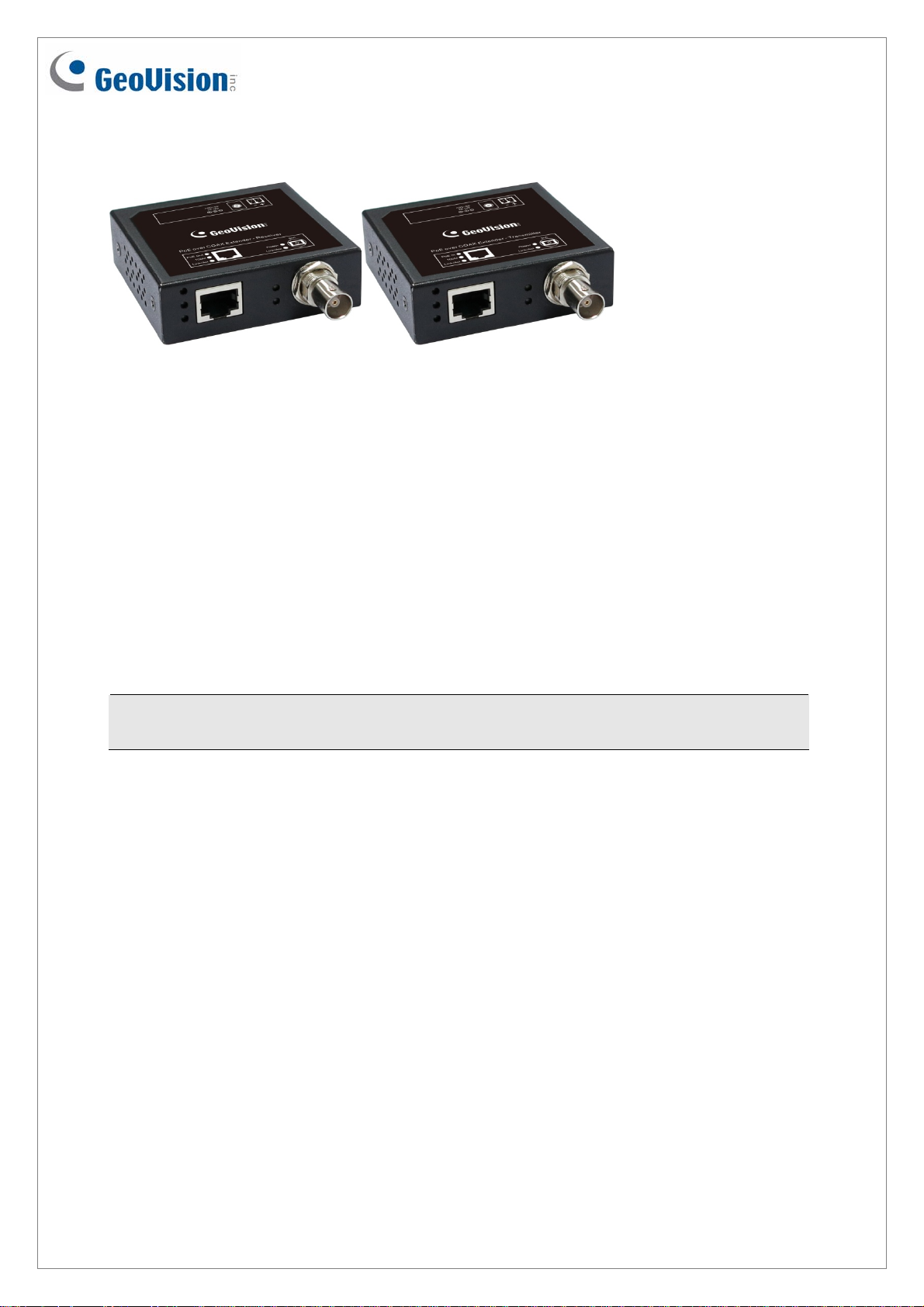
1. Power over Coaxial Cable Extender
Transmitter x 1
2. Power over Coaxial Cable Extender
Receiver x 1
3. Installation Guide x 1
4. Power Adapter x 1
5. Power Cord x 1
Note: If any of these items is found missing or damaged, please contact your local
supplier for replacement.
July 11, 2016
1
Page 2
Overview
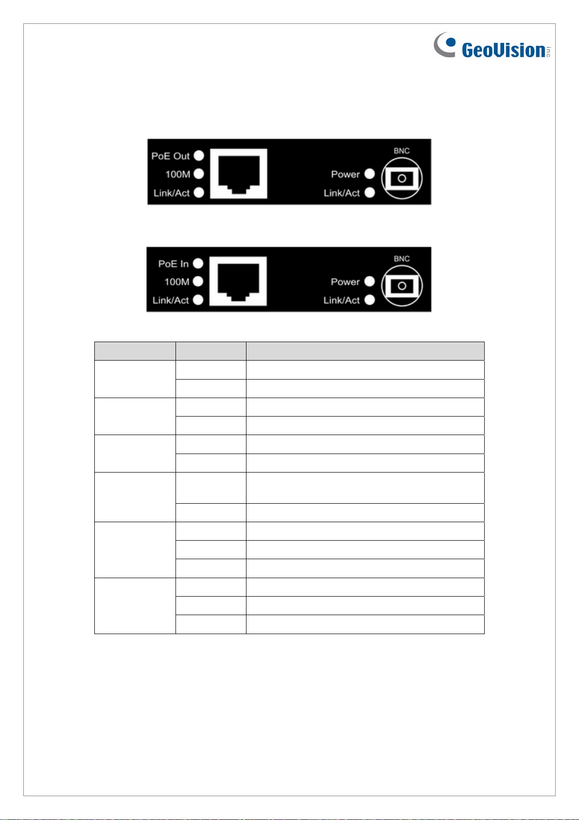
Transmitter
Receiver
LED Status Description
Green On Power is on.
Power
Off Power is off.
Yellow on Transmitting PoE Power PoE Out
(Transmitter)
Off Not Transmitting PoE Power
Yellow on Receiving PoE Power PoE In
(Receiver)
Speed (100 m
/ 328 ft)
Off Not Receiving PoE Power
Green on Transmitter/Receiver under 100 m (328 ft)
mode
Off Transmitter/Receiver under 10 m (32.8 ft) mode
Ethernet
Link/Act
Green on Ethernet Cable Connected
Blinking Transmitting/Receiving Data via Ethernet Cable
Off Ethernet Cable Not Connected
Coaxial
Link/Act
Green on Coaxial Cable Connected
Blinking Transmitting/Receiving Data via Coaxial Cable
Off Coaxial Cable Not Connected
2
July 11, 2016
Page 3

Application Diagram
Setup 1:
Note: Transmitter is powered by PSE/PoE+, using 100 m (328 ft) RJ-45 Cable.
Setup 2:
Note: Transmitter is powered by adapter.
Coaxial Cable
Type
RG6 (5C2V)
RG11 (7C)
RG6 (5C2V)
RG11 (7C)
Coaxial Cable
Length
180 Meters
(590.5 Feet)
230 Meters
(754.6 Feet)
180 Meters
(590.5 Feet)
230 Meters
(754.6 Feet)
Transmitter Power
Source
PoE Power Available
from Receiver
54V DC External power 14.05 Watts
54V DC External power 26.34 Watts
GeoVision PoE+ Switch /
3rd Party 56V PoE+ switch
GeoVision PoE+ Switch /
3rd Party 56V PoE+ switch
10.45 Watts
18.06 Watts
Note:
1. Users can choose to supply power to Transmitter by either PoE+ switch or adapter,
depending on their network environment. For instance, users who own a PoE+ switch
may choose to apply Setup 1.
2. Be sure to connect the coaxial cable at both ends (BNC ports of Transmitter and
Receiver) before powering the device.
July 11, 2016
3
Page 4

Specifications
Ports
Number of Ports 1-Port, 10/100BaseT(X), PoE over Coaxial Extender
IEEE 802.3 10BaseT
Network Standard
IEEE 802.3u 100BaseTX
IEEE 802.3af/at
Connectors
Cables
Mechanical Characteristics
LED
Indicators
Electrical Characteristics
Power Input
PoE Power IEEE 802.3at Compliant Voltage, Per Port Max. 30 watts
Power Output and
Range
Transmitter
Receiver
Ethernet: 10/100BaseT(X), RJ45 Connector, Auto-MDI/MDI-X
BNC Connector
PoE+: Cat.5e above
PoC: RG6 (75Ω), RG11 (75Ω)
5 LEDs: PoE Out, 100 m (328 ft), Ethernet Link/Act, Coaxial Power,
BNC Link/Act
5 LEDs: PoE In, 100 m (328 ft), Ethernet Link/Act, Coaxial Power,
BNC Link/Act
Power Adapter: 100 ~240V AC to 54V DC / 0.92A
5.5/2.1 mm DC Jack and 2-pin Terminal Block
For typical copper-core video coax. A full-rate network connection can
be established over RG6 (5C2V) and RG11 (7C)
The PoE power availability (measured from PoC Receiver PoE Out
port) depends on the length of coaxial cable and power source
connected to the Transmitter:
• PoE+ switch: 10.45 watts max. (RG6) and 18.06 watts max (RG11)
• External 54V power supply: 14.05 watts max. (RG6) and 26.34
watts max. (RG11)
General
Dimensions
(H x W x D)
Weight 135 g (0.3 lb)
Operating Temperature 0°C ~ 50°C (32°F ~ 122°F)
Storage Temperature -20°C ~ 85°C (-4°F ~ 185°F)
Humidity 10 to 90% RH (non-condensing)
Note: Specifications are subject to change without prior notice.
22 x 71 x 66 mm (0.87” x 2.8” x 2.6”) (BNC Connector excluded)
4
July 11, 2016
 Loading...