

Page 1

GV-NET Card V3.2
The GV-NET Card is a RS-485 / RS-232 interface converter. This Card connects to the RS232 port or USB port on your computer, and allows RS-485 devices, such as PTZ domes, to
be connected through the Card.
System Requirements
If the GV-NET/IO Card is listed as Prolific USB-to-Serial Comm Port under Windows
Device Manager, GV-System version 8.2 or above is required. If the GV-NET/IO Card is
listed as XR21B1411 USB UART under Windows Device Manager, GV-System version
8.5.7.0 or above is required.
To see how to check the device name under Windows Device Manager, refer to Installing
USB Driver later in this Installation Guide.
Packing List
1. GV-NET Card x 1
2. RJ-11 to DB9 Cable x 1
3. RJ-11 to USB Cable x 1
4. Pin Internal USB Cable x 1
5. Pin to 4-Pin Mini Power Cable x 1
February 10, 2015
1
Page 2
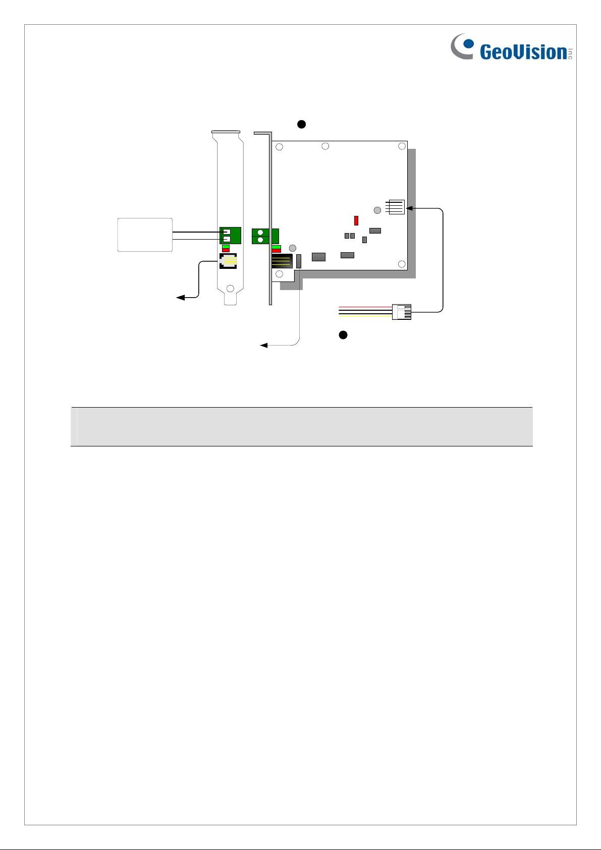
Overview
1
GV-NET Card
ON
RS-485 +
RS-485 -
Connects to
PC's COM port
or USB port
Connects to the USB
Connectors on t he PC's
motherboard
+-
4-pin to 4-pin
5
Mini PowerCable
GV-Net Card V3.2 Connections
Note: The GV-NET Card only provides RS-485 / RS-232 data conversion; the connection
to the GV-Video Capture Card is not required.
2
February 10, 2015
Page 3
Connections with Two Video Capture Cards
If your system is equipped with two video capture cards, connect the GV-NET/IO Card to the
video capture card of 1-16 channels.
Connections in NET/IO Card Mode
For the connections in the NET/IO Card Mode, please follow the instructions below:
• It is required to connect the GV-NET/IO Card to GV-Video Capture Card with the 20-Pin
Ribbon Cable.
• If you want to connect the GV-NET/IO Card to RS-485 devices, you have three ways of
connections. See below.
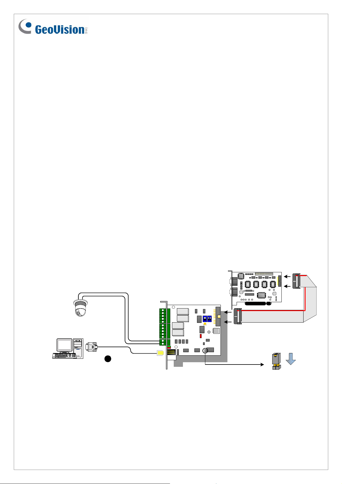
Three Ways of Connections of GV-NET/IO Card and RS-485 Devices:
1. You can connect a RJ-11 to DB9 Cable to the PC's COM Port when a RS-485 device is
connected. (Allowed for AC/DC Output Voltage)
GV Video CaptureCard
O
O
N
N
O
1
1 2
1
PTZ Dome
Connects to PC's COM Port
RJ-11 to DB9 Cable
3
RS-485+
RS-485-
N
With 2-pin header
February 10, 2015
3
Page 4

2. You can connect a RJ-11 to USB Cable to the PC's USB Port when a RS-485 device is
connected. (Allowed for AC/DC Output Voltage)
GV Video Capture Card
O
O
N
N
O
1
1 2
1
PTZ Dome
N
RS-485+
4
RJ-11toUSBCable
RS-485-
With 2-pin header
Connects to PC's USB Port
Note: It is required to install the USB driver. For details, see Installing USB Driver later in
the Installation Guide.
3. You can connect a 3-Pin Internal USB Cable to the USB Connectors on the PC's
Motherboard when a RS-485 device is connected. (Allowed for AC/DC Outpu t
Voltage)
GV Video Capture Card
O
O
N
N
O
1
1 2
1
PTZ Dome
VCC
(white)
DM (D-)
(green)
DP (D+)
(black)
GND
Connects to the USB
Connectors on the PC's
motherboard
5
3-pin Internal
USB Cable
GND
DM
DP
RS-485+
RS-485-
(white)
(green)
(black)
N
With 2-pi n header
Note: It is required to install the USB driver. For details, see Installing USB Drive later in
the Installation Guide.
4
February 10, 2015
Page 5

Connections In I/O Box Mode
For the connections in the I/O Box Mode, please follow the instructions below:
• It is not necessary to connect the GV-NET/IO Card to GV-Video Capture Card.
• Connect the GV-NET/IO Card to the PC by one of the following three ways.
Note: When you want to use any of GV-I/O 12-In Card and GV-I/O 12-Out Card with GV-Net/IO
Card, it is required to use both of 12-In Card and 12-Out Card together for work.
Three Ways of Connections of GV-NET/IO Card and PC:
1. You can connect a RJ-11 to DB9 Cable to the PC's COM Port. (Allowed for AC/DC
Output Voltage)
Connects to PC's COM Port
Chaining together with
GV-NET/IO Card V3.1
or later / GV-IO USB
Box
RJ-11 to DB9Cable
3
RS-485+
RS-485-
GV Video Capture Card
O
O
N
N
O
1
1
1 2
N
Without
2-pin header
2. You can connect a RJ-11 to USB Cable to the PC's USB Port. (A llowed for DC Outp u t
Voltage only)
Chaining together with
GV-NET/IO Card V3.1
or later / GV-IO USB
Box
GV Video Capture Card
O
O
N
N
O
1
1 2
1
N
Connects to PC's USBPort
Note: It is required to install the USB driver. For details, see Installing USB Driver later in the
Installation Guide.
February 10, 2015
4
RJ-11 to USB Cable
RS-485+
RS-485-
5
Without
2-pin header
Page 6

3. You can connect a 3-Pin Internal USB Cable to the USB Connectors on the PC's
Motherboard. (Allowed for DC Outpu t Voltage only)
VCC
(white)
DM (D-)
(green)
DP (D+)
(black)
GND
Connects to the USB Connectors on
the PC's motherboard
3-pin Internal
5
USB Cable
Chaining together with
GV-NET/IO Card V3.1
or later / GV-IO USB
Box
DM
(white)
DP
(green)
GND
(black)
RS-485+
RS-485-
GV VideoCapture Card
O
O
N
N
O
1
1 2
1
N
Without
2-pin header
Note: It is required to install the USB driver. For details, see Installing USB Driver later in the
Installation Guide.
Switching Modes
The GV-NET/IO Card provides two modes for users to expand its capability: I/O Box Mode
and NET/IO Card Mode. With a mode-switch jumper to insert on the 2-pin header, you can
switch between modes.
• NET/IO Card Mode (default): With the switch jumper inserted, this default mode acts as
a GV-NET/IO Card. It is required to connect the GV-NET/IO Card to the GV-Video
Capture Card for usage.
• I/O Box Mode: Without the switch jumper inserted, the GV-NET/IO Card can work as an
independent device. It is NOT necessary to connect to the GV-Video Capture Card for
usage.
6
February 10, 2015
Page 7

Extended Connections
Via the RS-485 connectors, up to 4 GV-NET/IO Cards can be chained together when the GVNET/IO Card is on the I/O Box mode. For extended connections, the address assignment is
shown below.
Note: When the GV-NET/IO Card is set to the I/O Box Mode, it can have extended
connections with GV-I/O Boxes.
DIP Switch
February 10, 2015
7
Page 8

Installing USB Driver
To use the USB function, it is required to install the driver on the PC. Follow these steps to
install the driver:
1. Insert the software DVD. It will run automatically and pop up a window.
2. Click Install GeoVision USB Devices Driver. This dialog box appears.
3. Click Install to install the drivers. When the installation is complete, this message will
appear: Install Successfully.
4. Click Exit to close the dialog box and restart the PC.
To verify the drivers are installed correctly, go to Windows Device Manager after restarting
the PC. Expanding the Ports field, you should see Prolific USB-to-Serial Comm Port or
XR21B1411 USB UART depending on the version of the driver. The COM number in the
parenthesis indicates the COM port currently in use.
Note: If you unplug the GV-NET/IO Card from the PC and connect another GV-Net/IO
Card to the same USB port, the COM port may still be changed. Access the Windows
Device Manager again to look up the new COM port number.
8
February 10, 2015
Page 9

Specifications
32-bit Windows XP / Vista / 7 / 8 / Server 2008
OS
64-bit Windows 7 / 8 / Server 2008 / Server 2012
Input 4
Input
Input Signal Dry Contact, Wet Contact 9~30V AC / DC
Relay Output 4
Relay Status Normal Open
Output
Relay Capacitance
Interface
Mode
Switch
Address
Communication
Operating Temperature
I/O Box Mode Without GV-Video Capture Card
NET/IO Card Mode With GV-Video Capture Card
USB Connection 30V DC, 3A
125 / 250V AC, 3A
RS-232 Connection
30V DC, 3A
RJ-11 to DB9
RJ-11 to USB
3-Pin Internal USB to Internal USB
1~4
RS-485, USB, RS-232
0° C ~50° C / 32°F ~122 °F
Humidity 5% ~ 95% (Non-Condensing)
Compatible Mod el
Dimensions (W x H)
February 10, 2015
All GV-Video Capture Card Models
99 x 90 mm / 3.90 x 3.54 in
9
 Loading...