

Page 1
Models
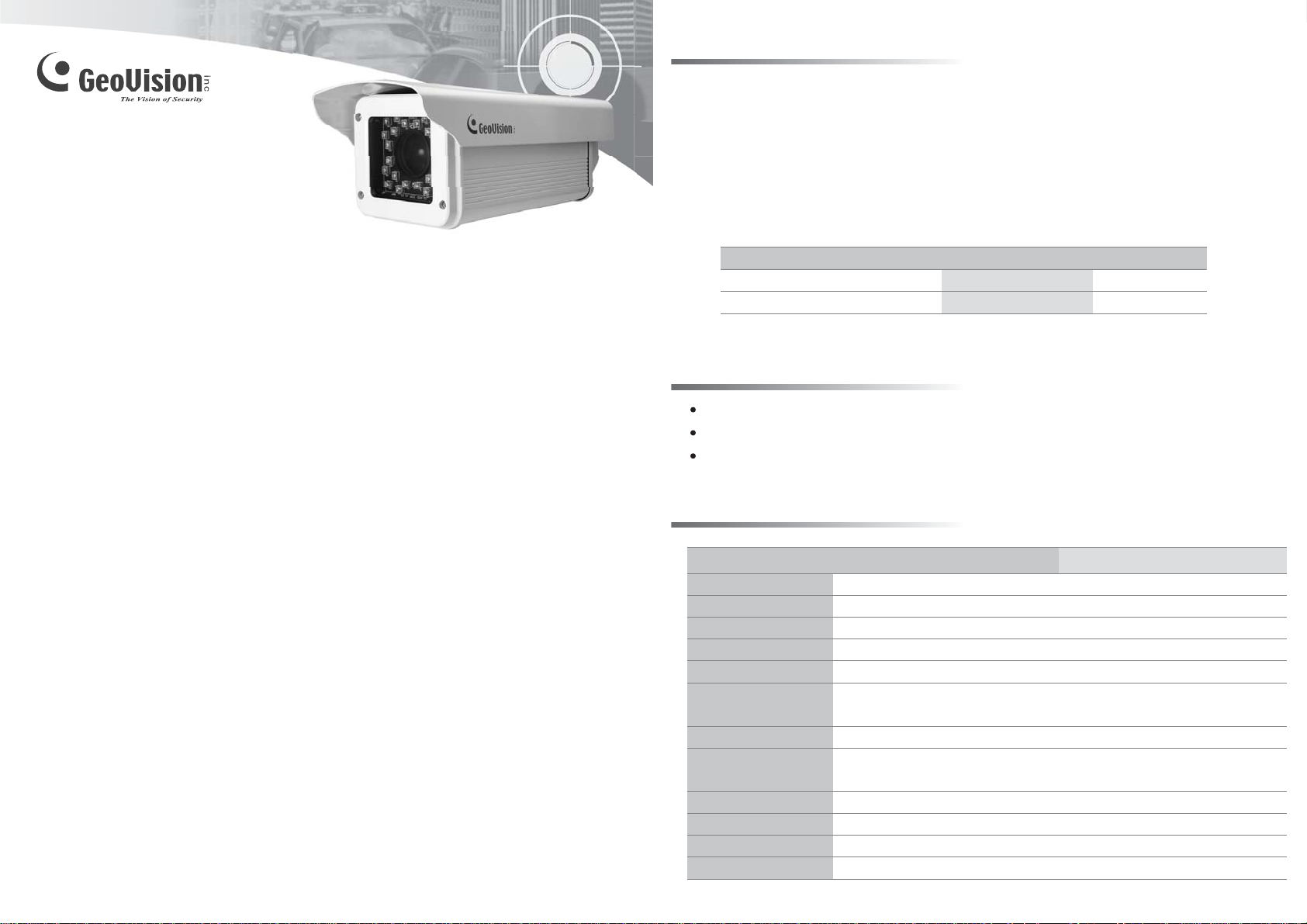
The GV-LPR CAM gives a 570TVL high-contrast license plate recognition video to the GV-LPR
software that identifies license plates. The camera features 24 high-efficient LEDs for an
illumination range of 30 meters. The camera also features a weather-sealed IP66-compliant
housing with the heater and blower inside. This installation guide will take you through the
functionality and use of the GV-LPR CAM.
List of Models
GV-LPR CAM V2.0
Installation Guide
Before attempting to connect or operate this product,
please read these instructions carefully and save this manual for future use.
Model
GV-LPR CAM 20M EIA DC12V
GV-LPR CAM 20M CCIR DC12V
Packing List
AC Power Cable (110-125V, 10A) x 1
Power Adapter (100-240V, 12V/5A) x 1
Outdoor Mounting Bracket x 1
Specifications
GV-LPR CAM 20M EIA DC12VModel GV-LPR CAM 20M CCIR DC12V
Sensor
Heater
Resolution
Construction
Protection classification
Temperature
LED Quantity
IR Distance
Illumination View Angle
Illuminator Life
Power Supply
Power Consumption
1/3" B/W EXview CCD
IR Optimal Distance
20 m / 65.61 ft
20 m / 65.61 ft
≤ 5˚C (ON) , > 5˚C (OFF) ; 20W
570 TVL
Robust aluminum with weatherproof sun-shield
IP 66
Operation: -30˚C ~ 50˚C / -22˚F ~ 122˚F
Storage: -30˚C ~ 70˚C / -22˚F ~ 158˚F
24 high-efficient LEDs
30 m / 98.43 ft
20 ± 5 m / 65.62 ± 16.4 ft (optimal)
30°
25,000 hrs
DC 12V
30W (normal), 50W (heater on)
Video Format
NTSC
PAL
© 2010 April GeoVision Inc. All rights reserved.
LPRCAMV20-A
Page 2
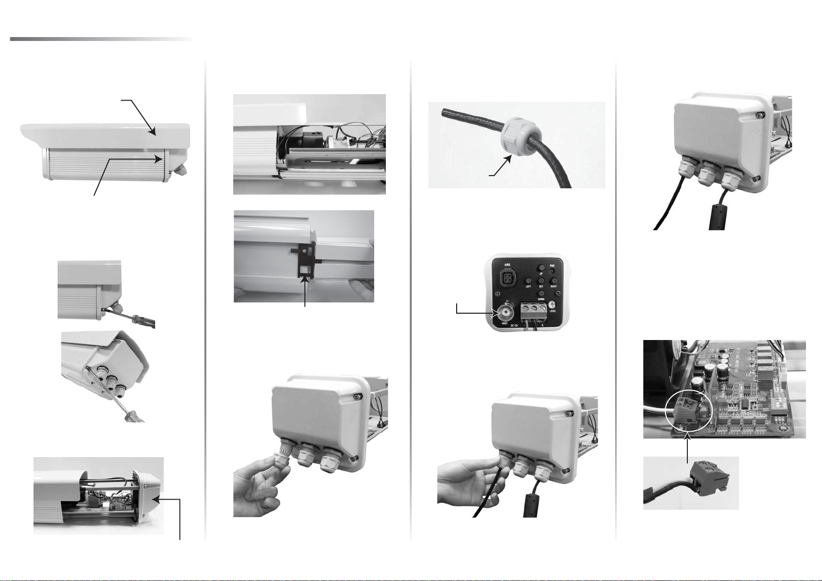
Installing Camera Module
Push the sun shield forward to align with
1. Slightly lift the camera module and slide it
the back of camera enclosure.
Sun Shield
Camera Enclosure Back
2.
Loosen the set screws on the back of the
camera enclosure.
4.
out completely.
Completely slide the camera
module out
Insert the video cable through the screw
6.
cap.
Screw Cap
7.
Attach the video cable to the BNC
connector and plug it into the “VIDEO OUT”
jack.
VIDEO OUT
Jack
Loosen the screw cap on the right, insert
9.
the power cable through the screw cap.
Remove the terminal block. Plug black and
10.
white wires of the power cable to the
terminal block. Reinsert the terminal block
onto the camera. The white wire is required
to connect to the positive pin (+) on the
camera and the black wire to the negative
pin (-).
Pull out the camera module.
3.
Camera Module
Adjust the length of the video cable and
Loosen the screw cap on the left.5.
8.
then tightly screw the cap.
Adjust the length of the cable and then
11.
tightly screw the cap (see Steps 8 for the
pictures).
Page 3

Adjusting Camera Settings
Overview
No
Function
1
89
7
6
1
5
4
2
3
Shutter Speed
See the lists below for shutter speed settings.
Distance between the object and the
camera is 550 cm (18.04 ft).
165 SEC
182 SEC
183 (*) SEC
184 SEC
185 SEC
225 SEC
Notes:
1. The default settings are marked with (*).
2. The gray areas in the charts are not recommended for use.
LED Brightness Settings
The GV-LPR CAM is designed with 24 high-efficient LEDs which you can adjust the brightness.
You can push up (ON) and down (OFF) the switches of SW2, SW3 and SW4 for LED
brightness settings. See the table below for 8 LED brightness setting values.
Note: The factory default setting of SW1 is ON. If you find the images of license plates captured
in the day time or sufficient lights are unclear, check the SW1 and make sure it is switched to
ON.
Auto Iris lens connector
2
Video out
3
Power Terminal (It is already connected. Follow
Steps 11 to 12 in Installing Camera Module to
insert the Power Cable.)
4
Moves down the OSD menu.
5
Moves the focus rightward to select menu options.
6
Power LED
7
Moves up the OSD menu.
8
Enters the OSD menu option and confirms the
selection
9
Moves the focus leftward to select menu options.
Distance between the object and the
camera is 1100 cm (36.08 ft).
145 SEC
150 SEC
155 SEC
170 SEC
180 SEC
200 SEC
SW2
1
ON
2
ON
3
ON
ON
4
OFF
5
OFF
6
OFF
7
OFF
8
SW3
ON
ON
OFF
OFF
ON
ON
OFF
OFF
SW4
ON
OFF
ON
OFF
ON
OFF
ON
OFF
LED Brightness (mA)
470 (Default Setting)
400
350
300
250
200
150
100
OSD Menu Options and Functions
Main Menu
LENS
SHUTTER
BLC
(Backlight
Compensation)
AGC (Automatic
Gain Control)
WHITE BAL.
(White Balance)
ADJUST
FUNCTION
RESET
EXIT
Note: The factory default GAMMA value is set to be 1. It will be adjusted to 0.45 every time when you select
RESET. For optimal image performance, it is recommended to adjust the GAMMA value to 1.
Sub Menu
MANUAL
DC
FIXED
MANUAL
AUTO
OFF
ON BLC AREA
BLC RATIO
OFF
ON
ATW
AWB
FIXED
MANUAL
CONTRAST
SHARPNESS
CB_GAIN
CR_GAIN
CMAERA ID
MIRROR
MOTION
PRIVACY
GAMMA
LANGUAGE
-
-
Function
Manually adjust the camera lens.
Press SET to adjust the lens brightness.
Includes these options: 1/60, 1/100, 1/250,
1/500, 1/2000, 1/5000, 1/10000, 1/100000.
Press SET to manually adjust the shutter
speed.
Not available when the LENS is set at DC.
Turn off BLC function.
Press SET to configure the areas.
Press SET to adjust the sensitivity values.
Turn off AGC function.
Press SET to adjust the AGC ratio values.
Auto Tracking White Balance
Automatic White Balance
Press SET to select the mode from 1 to 4.
Press SET to adjust Red and Blue gain.
Adjust the Contrast from values 0 to 255.
Adjust the Sharpness from values 0 to 255.
Adjust CB_GAIN from values 0 to 255.
Adjust CR_GAIN from values 0 to 255.
Press SET to name the camera.
Select ON to reverse the image.
Select ON and press SET to configure
MOTION areas.
Select ON and press SET to configure
PRIVACY areas.
Adjust the gamma values to control brightness.
Higher gamma value shows darker images.
Press SET to change the language setting of
OSD menu options.
Press SET to restore to the factory defaults.
Close the OSD menu.
Default Setting
1/500
Brightness: 70
87
10
176
176
OFF
OFF
OFF
OFF
1
English
-
-
-
-
-
-
-
-
-
-
Page 4

Installing Camera Enclosure
After the installation of camera module and settings adjustment, you are now ready to install the
camera enclosure back.
1. Adjust the lens focus. 2. Lift the camera module.
4.
3.
Align the camera module to the camera
enclosure and slide it back.
Secure the camera enclosure with the
screws on both sides.
Push the sun shield back.5.
9F, No. 246, Sec. 1, Neihu Rd.,
Neihu District, Taipei, Taiwan
Tel: +886-2-8797-8377
Fax: +886-2-8797-8335
sales@geovision.com.tw
http://www.geovision.com.tw
 Loading...