

Page 1
Before attempting to connect or operate this product,
please read these instructions carefully and save this manual for future use.
User's Manual
User's Manual
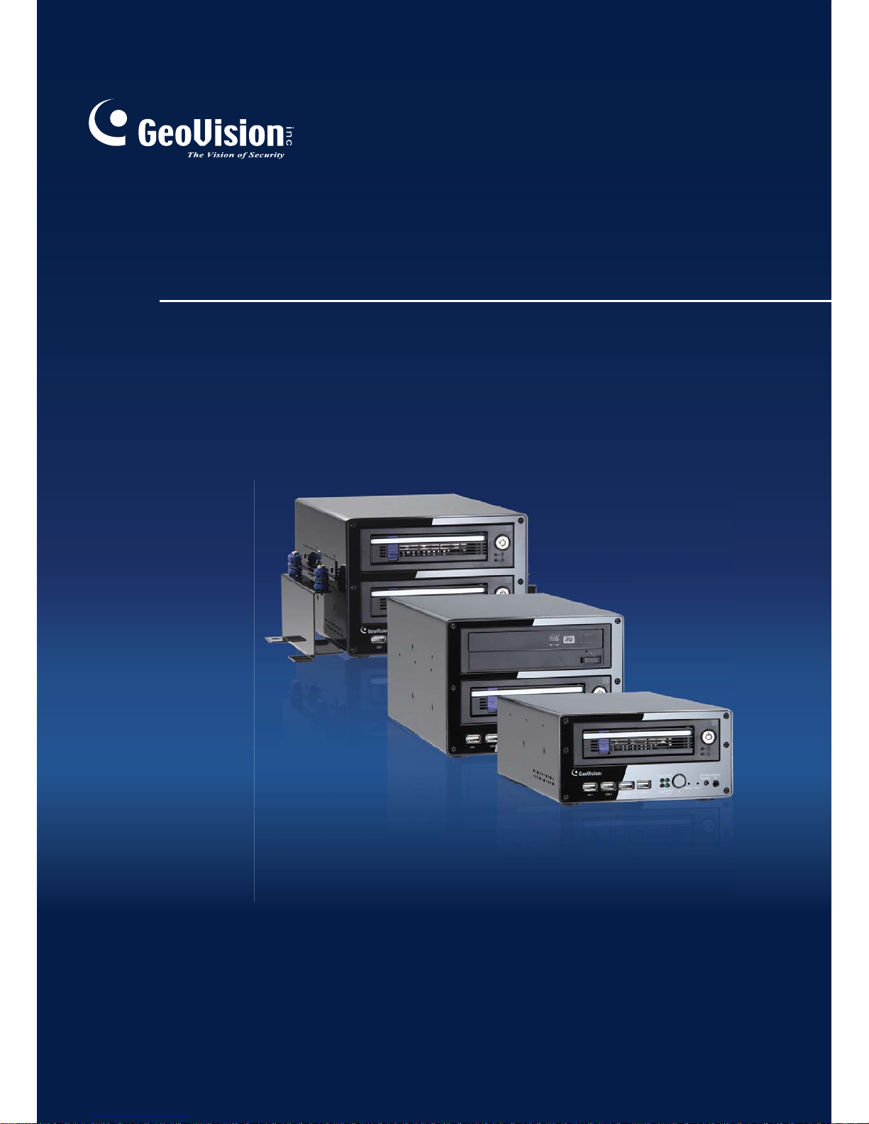
GV-Compact DVR V3
CDVR3-4CHV101-8CHV10-A
Page 2
© 2012 GeoVision, Inc. All rights reserved.
Under the copyright laws, this manual may not be copied, in whole or in part,
without the written consent of GeoVision.
Every effort has been made to ensure that the information in this manual is
accurate. GeoVision, Inc. makes no expressed or implied warranty of any kind
and assumes no responsibility for errors or omissions. No liability is assumed
for incidental or consequential damages arising from the use of the information
or products contained herein. Features and specifications are subject to
change without notice.
GeoVision, Inc.
9F, No. 246, Sec. 1, Neihu Rd.,
Neihu District, Taipei, Taiwan
Tel: +886-2-8797-8377
Fax: +886-2-8797-8335
http://www.geovision.com.tw
Trademarks used in this manual: GeoVision, the GeoVision logo and GV
series products are trademarks of GeoVision, Inc. Windows and Windows XP
are registered trademarks of Microsoft Corporation.
January 2012
Page 3
i
Preface
Welcome to the GV-Compact DVR V3 User’s Manual.
The GV-Compact DVR V3 has a series of models designed to meet different needs. This
Manual is designed for the following models and firmware version:
Note: Be sure to restore the four-channel GV-Compact DVR V3 to default settings
after upgrading the firmware to V1.01. For details, see 8.4 Restoring to Factory Default
Settings.
The Four-Channel Unit
Models Model Name Firmware Version
GV-LX4C3D1
GV- LX4C3D2
Standard Models
GV- LX4C3D2W
Anti-Vibration ACC Model GV-LX4C3V
1.01
The Eight-Channel Unit
Models Model Name Firmware Version
GV-LX8CD1
GV-LX8CD2
Standard Models
GV-LX8CD2W
GV-LX8CV1
Anti-Vibration ACC Models
GV-LX8CV2
1.00
Page 4

ii
Contents
Chapter 1 Introduction ..........................................................1
1.1 Features..................................................................................................................2
1.2 Models ....................................................................................................................3
1.2.1 The Four-Channel Unit ...............................................................................3
1.2.2 The Eight-Channel Unit...............................................................................4
1.3 Packing List............................................................................................................5
1.3.1 The Four-Channel Unit................................................................................5
1.3.2 The Eight-Channel Unit...............................................................................7
1.4 Options ...................................................................................................................9
1.5 System Requirement ...........................................................................................10
Chapter 2 Physical Description..........................................11
2.1 Front Panel ...........................................................................................................11
2.1.1 The Four-Channel Unit .............................................................................11
2.1.2 The Eight-Channel Unit.............................................................................14
2.2 Rear Panel ............................................................................................................18
2.2.1 The Four-Channel Unit .............................................................................18
2.2.2 The Eight-Channel Unit.............................................................................20
2.3 Remote Control....................................................................................................22
2.3.1 The Four-Channel Unit .............................................................................22
2.3.2 The Eight-Channel Unit.............................................................................24
Chapter 3 Getting Started ...................................................26
3.1 Basic Connection for Standard Models.............................................................27
3.1.1 The Four-Channel Unit..............................................................................27
3.1.2 The Eight-Channel Unit.............................................................................28
3.2 Basic Connection for Anti-Vibration Models.....................................................29
3.2.1 The Four-Channel Unit..............................................................................29
3.2.2 The Eight-Channel Unit.............................................................................30
3.3 Connecting Anti-Vibration ACC Models ............................................................31
3.3.1 Connecting and Testing ............................................................................31
3.3.2 Connecting to a vehicle.............................................................................33
3.4 Connecting Optional Video Output Devices .....................................................38
3.4.1 The Four-Channel Unit..............................................................................38
3.4.2 The Eight-Channel Unit.............................................................................39
3.5 Installing a Hard Drive.........................................................................................40
3.5.1 The Four-Channel Unit..............................................................................40
3.5.2 The Eight-Channel Unit.............................................................................43
3.6 Turning On / Off the Power.................................................................................45
3.6.1 Turning On the Power...............................................................................45
3.6.2 Turning Off the Power...............................................................................45
Page 5

iii
3.7 Formatting a Hard Drive......................................................................................46
3.8 Main Screen Overview.........................................................................................47
3.9 Basic Operation ...................................................................................................48
3.9.1 Date/Time Adjustment...............................................................................48
3.9.2 Recording Operation.................................................................................48
3.9.3 Search/Playback Operation ......................................................................49
3.9.4 PTZ Operation...........................................................................................49
3.9.5 Channel Number and Camera Name........................................................49
3.9.6 Video Backup............................................................................................49
Chapter 4 OSD Menu Configurations ................................50
4.1 Channel Settings .................................................................................................52
4.1.1 Channel Name ..........................................................................................52
4.1.2 Video/Audio Settings.................................................................................53
4.1.3 Motion Detection .......................................................................................54
4.1.4 Motion Trigger Output Settings .................................................................56
4.1.5 Alarm Settings...........................................................................................57
4.1.6 Camera Settings .......................................................................................57
4.1.7 PTZ Settings .............................................................................................58
4.1.8 PTZ Control...............................................................................................59
4.1.9 Privacy Mask.............................................................................................60
4.2 Digital IO Settings................................................................................................61
4.2.1 Digital Input Settings .................................................................................61
4.2.2 Digital Output Settings ..............................................................................62
4.2.3 GPS Settings ............................................................................................63
4.3 Events and Alerts ................................................................................................65
4.3.1 E-mail........................................................................................................66
4.3.2 FTP ...........................................................................................................67
4.3.3 Center V2..................................................................................................68
4.3.4 VSM ..........................................................................................................69
4.3.5 GV-GIS......................................................................................................70
4.3.6 Video Gateway / Recording Server...........................................................71
4.3.7 Remote Playback......................................................................................72
4.3.8 3GPP.........................................................................................................73
4.4 Monitoring Settings .............................................................................................74
4.5 Recording Schedule ............................................................................................76
4.5.1 Specific Day ..............................................................................................76
4.5.2 Channel Schedule.....................................................................................77
4.5.3 I/O Monitoring Schedule............................................................................78
4.6 Search / Playback ................................................................................................79
4.6.1 Time Map List............................................................................................79
4.6.2 List All........................................................................................................80
4.6.3 Manual Recording List ..............................................................................80
4.6.4 Alarm Recording List.................................................................................80
4.6.5 Motion Recording List ...............................................................................80
Page 6

iv
4.6.6 Time Search..............................................................................................80
4.6.7 Advanced Search......................................................................................81
4.7 Network.................................................................................................................82
4.7.1 Network Status..........................................................................................82
4.7.2 Connection Settings..................................................................................83
4.7.3 Wireless Settings ......................................................................................84
4.7.4 Advanced TCP/IP......................................................................................85
4.7.5 UMTS Settings..........................................................................................86
4.7.6 DDNS Settings..........................................................................................87
4.7.7 Multicast Settings......................................................................................88
4.7.8 Web User Account Info .............................................................................89
4.8 Advanced..............................................................................................................90
4.8.1 Date and Time...........................................................................................90
4.8.2 Firmware Settings .....................................................................................91
4.8.3 Storage Settings........................................................................................92
4.8.4 Display Settings ........................................................................................93
4.8.5 Spot Monitor Settings................................................................................94
4.8.6 Alert Settings.............................................................................................95
4.8.7 System Settings ........................................................................................96
4.8.8 System Log ...............................................................................................97
4.8.9 Backup ......................................................................................................98
Chapter 5 Remote Viewing Using A Web Browser...........99
5.1 Assigning an IP Address ....................................................................................99
5.1.1 Using OSD Menu ......................................................................................99
5.1.2 Connecting with a PC..............................................................................100
5.2 Accessing Your Surveillance Images ..............................................................102
5.3 Functions Featured on the Main Page.............................................................103
5.3.1 The Live View Window............................................................................104
5.3.2 The Control Panel of the Live View Window...........................................105
5.3.3 Snapshot of a Live Video ........................................................................106
5.3.4 Video Recording......................................................................................106
5.3.5 Picture-in-Picture and Picture-and-Picture View.....................................107
5.3.6 Alarm Notification....................................................................................109
5.3.7 Video and Audio Configuration ...............................................................110
5.3.8 Remote Configuration .............................................................................110
5.3.9 Camera Name Display............................................................................110
5.3.10 Image Enhancement.............................................................................111
5.3.11 PTZ Control...........................................................................................111
5.3.12 Visual PTZ.............................................................................................112
5.3.13 I/O Control.............................................................................................113
5.3.14 Visual Automation .................................................................................114
5.3.15 Multicast................................................................................................115
5.3.16 Network Status......................................................................................116
Page 7

v
Chapter 6 Remote Configurations ...................................117
6.1 Video & Motion...................................................................................................119
6.1.1 Video Settings.........................................................................................119
6.1.2 Motion Detection .....................................................................................123
6.1.3 Text Overlay............................................................................................124
6.1.4 Visual Automation ...................................................................................125
6.1.5 VGA Output Settings...............................................................................126
6.1.6 Video Channel Source Settings ..............................................................126
6.2 Digital I/O & PTZ.................................................................................................127
6.2.1 I/O Control...............................................................................................127
6.2.2 PTZ Settings ...........................................................................................129
6.2.3 GPS ........................................................................................................130
6.2.4 Buzzer.....................................................................................................132
6.2.5 Spot Monitor............................................................................................133
6.3 Events & Alerts ..................................................................................................134
6.3.1 E-mail......................................................................................................135
6.3.2 FTP .........................................................................................................136
6.3.3 Center V2................................................................................................138
6.3.4 VSM ........................................................................................................140
6.3.5 GV-GIS ...................................................................................................142
6.3.6 Backup Center ........................................................................................144
6.3.7 Video Gateway / Recording Server.........................................................146
6.3.8 ViewLog Server.......................................................................................148
6.3.9 RTSP / 3GPP..........................................................................................149
6.4 Monitoring ..........................................................................................................150
6.5 Recording Schedule ..........................................................................................152
6.5.1 Recording Schedule Settings..................................................................152
6.5.2 I/O Monitoring Settings............................................................................153
6.6 Remote ViewLog................................................................................................154
6.7 Network...............................................................................................................155
6.7.1 LAN .........................................................................................................155
6.7.2 Wireless-Client Mode..............................................................................157
6.7.3 Advanced TCP/IP....................................................................................159
6.7.4 UMTS/ZigBee..........................................................................................162
6.7.5 Multicast..................................................................................................164
6.7.6 IP Filtering...............................................................................................166
6.7.7 SNMP Setting..........................................................................................167
6.8 Management.......................................................................................................168
6.8.1 Date & Time Setting................................................................................168
6.8.2 GPS Maps Settings.................................................................................170
6.8.3 Storage Settings......................................................................................171
6.8.4 User Account...........................................................................................173
6.8.5 Log Information .......................................................................................174
6.8.6 Tools .......................................................................................................175
6.8.7 ACC Settings...........................................................................................177
Page 8

vi
Chapter 7 Remote Recording and Playback ...................178
7.1 Remote Recording.............................................................................................178
7.2 Remote Playback ...............................................................................................178
7.2.1 Playback of Files Recorded on Hard Drive .............................................179
7.2.2 Playback over Network ...........................................................................180
7.2.3 Access to the Recorded Files through FTP Server.................................181
7.2.4 Playback of Backup Files........................................................................181
7.2.5 Playback of GPS Tracks .........................................................................183
Chapter 8 Advanced Applications ...................................186
8.1 Upgrading System Firmware ............................................................................186
8.1.1 Using the Web Interface..........................................................................187
8.1.2 Using the IP Device Utility.......................................................................188
8.2 Backing Up and Restoring Settings.................................................................190
8.2.1 Backing Up the Settings..........................................................................190
8.2.2 Restoring the Settings.............................................................................191
8.3 GPS Tracking .....................................................................................................192
8.4 Restoring to Factory Default Settings .............................................................194
8.5 Verifying Watermark..........................................................................................195
8.5.1 Accessing the Recorded Files.................................................................195
8.5.2 Running Watermark Proof.......................................................................195
8.5.3 The Watermark Proof Window................................................................196
Chapter 9 Mobile Phone Surveillance..............................197
9.1 Android Smartphone .........................................................................................198
9.1.1 Connecting to GV-Compact DVR V3 ......................................................198
9.2 iPhone and iPod Touch.....................................................................................201
9.2.1 Connecting to GV-Compact DVR V3 ......................................................202
Chapter 10 DVR Configurations.......................................204
10.1 Setting up GV-Compact DVR V3.....................................................................205
10.2 Remote Monitoring with Multi View ...............................................................209
10.3 Remote Monitoring with E-Map ......................................................................211
Chapter 11 CMS Configurations.......................................213
11.1 Center V2 ..........................................................................................................213
11.2 VSM...................................................................................................................215
11.3 Dispatch Server ...............................................................................................216
11.4 Control Center..................................................................................................217
Page 9

vii
Chapter 12 The I/O Terminal Block ..................................219
12.1 Pin Assignment.................................................................................................219
12.1.1 The Four-Channel Unit ...........................................................................219
12.1.2 The Eight-Channel Unit...........................................................................220
12.2 Output Devices .................................................................................................221
12.2.1 The Four-Channel Unit..........................................................................221
12.2.2 The Eight-Channel Unit...........................................................................222
12.3 Camera Power Supply......................................................................................224
12.3.1 The Four-Channel Unit..........................................................................224
12.3.2 The Eight-Channel Unit...........................................................................225
Specifications: The Four-Channel Unit..............................226
Specifications: The Eight-Channel Unit.............................230
Appendix……........................................................................234
A. Supported Wireless LAN USB Adaptor.............................................................234
B. Supported Mobile Broadband Device ...............................................................234
C. Settings for Internet Explore 8...........................................................................235
D. The CGI Command..............................................................................................236
E. The RTSP Command...........................................................................................237
F. Supported PTZ Cameras ...................................................................................238
G. Running IFS Driver under 32-bit Windows 7....................................................240
H. Default Port Value...............................................................................................243
Page 10

Introduction
1
1
Chapter 1 Introduction
The GV-Compact DVR V3 is a mobile video recorder that comes in the four-channel and
eight-channel units. The four-channel unit can simultaneously display real-time images from
four cameras, while the eight-channel unit can simultaneously display real-time images from
eight cameras.
The recording frame rate of each channel is adjustable up to 30 / 25 fps at the resolution of
704 x 480 (NTSC) / 704 x 576 (PAL). The dual-stream design allows you to set up two
different codec and resolutions for a single video transmission. In a limited bandwidth network,
you can enable the dual streams (for four-channel models only) to lower the resolution and
codec for live images, but still get the highest recording quality and smallest file size
compressed with H.264 codec.
The Anti-Vibration ACC model of the GV-Compact DVR V3 has already been tested to
withstand severe levels of shock and vibration in mobile environments. It is perfect to be
installed in any vehicles, such as buses and vans, for surveillance and recording.
The special design of the GV-Compact DVR V3 enables you to link up with TV, VGA and spot
monitors simultaneously for direct display. The GV-Compact DVR V3 offers many features
that you can expect to have.
Page 11

2
1.1 Features
Recording
• Dual streams from H.264 and MJPEG (for four-channel models only)
• Up to 120 fps at D1 resolution for 4-channel units; up to 240 fps at D1 resolution for
8-channel units
• Independent channel resolution, quality and frame rate settings
Local Display
• VGA output in high resolution (1280 x 1024)
• Display video on TV, VGA and Spot Monitor simultaneously
• GPS Speed Text overlay on live view and recordings
Storage and Backup
• 3.5” or 2.5” SATA HDD (3.5” to 2.5” HDD converter required)
• External USB mass storage devices
• DVD-RW Backup
• Backup Center for PC-based storage and backup solution
Monitoring
• Continuous, motion detection, schedule and input-triggered recordings
• Buzzer alarm on video lost, input triggered, motion detected and disk full
• 4 alarm inputs and outputs for the 4-channel unit; 8 alarm inputs and outputs for the
8-channel unit
Playback
• Retrieve video by date, time and event
• Remote playback
Remote Monitoring
• Mobile broadband (HSDPA, UMTS, EDGE, EVDO, etc.)
• Mobile Phone Surveillance (Android Smartphone, iPhone, iPad)
• Central monitoring systems Center V2, VSM, Control Center, Recording Server
• Geographic information system GV-GIS
• GPS tracking for the Anti-Vibration ACC models (GPS module required)
Language Support
• Support 16 languages on Web interface
Page 12
Introduction
3
1
1.2 Models
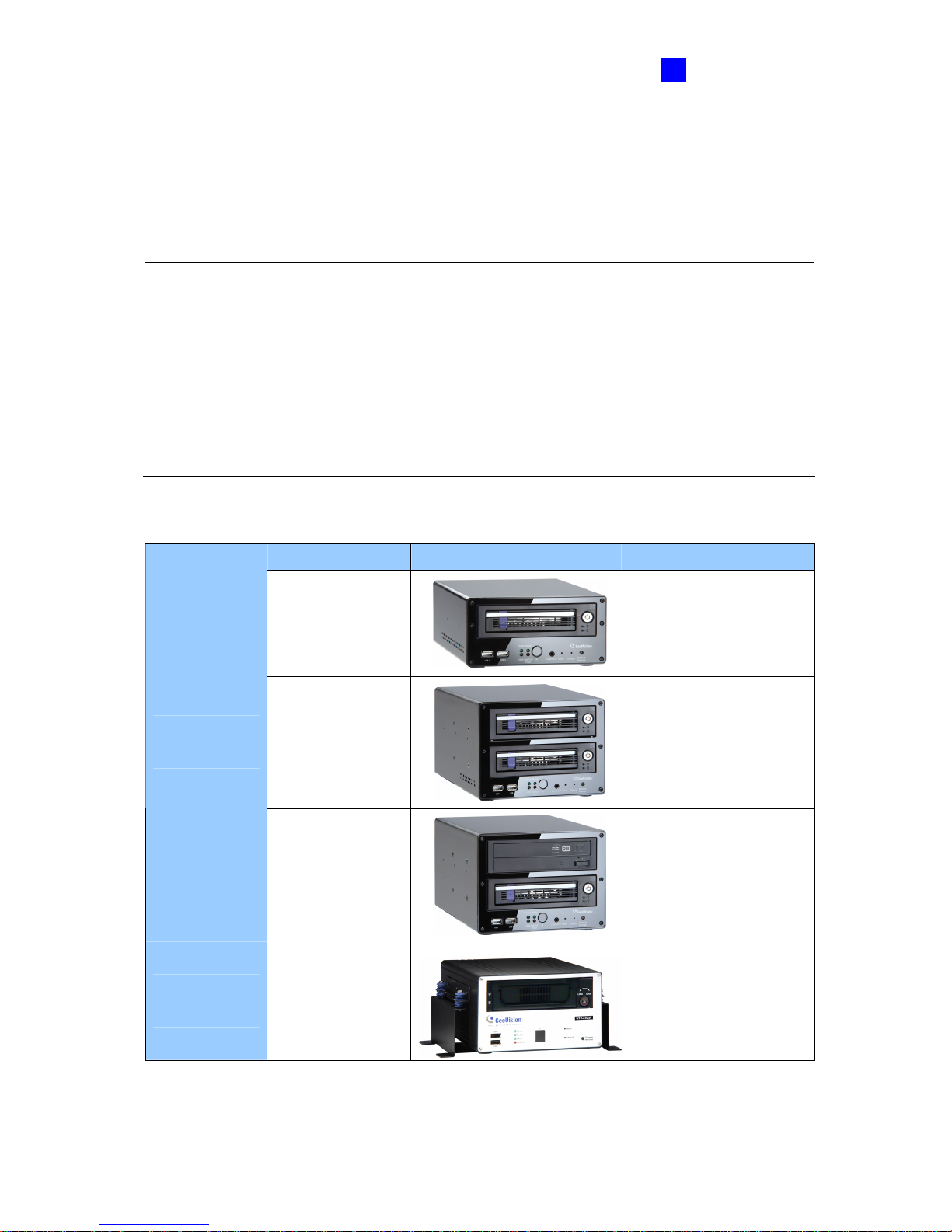
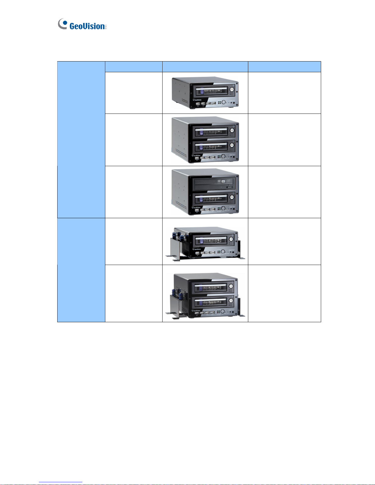
The GV-Compact DVR V3 comes in the four-channel and eight-channel units. Each unit is
available in the Standard models and the Anti-Vibration ACC models as listed below.
IMPORTANT:
1. Standard and Anti-Vibration ACC models have different internal designs. It is forbidden
to connect the Standard model to vehicle power supply.
2. For the Anti-vibration ACC models (GV-LX4C3V, GV-LX8CV1 and GV-LX8CV2), it is
necessary to use the hard drive especially for notebook, vehicle or surveillance
applications, and tightly fasten the unit on the vehicle to prevent vibration and shock
hazard.
1.2.1 The Four-Channel Unit
Model Name Image Description
GV-LX4C3D1
Equipped with 2 USB
ports and 1 hard drive
bay.
GV- LX4C3D2
Equipped with 2 USB
ports and 2 hard drive
bays.
Standard
models
GV- LX4C3D2W
Equipped with 2 USB
ports, 1 hard drive bay
and 1 DVD-RW drive.
Anti-Vibration
ACC model
GV-LX4C3V
Equipped with vibration
absorbers, 2 USB ports
and 1 hard drive bay.
Page 13
4
1.2.2 The Eight-Channel Unit
Model Name Image Description
GV-LX8CD1
Equipped with 4 USB
ports and 1 hard drive
bay.
GV-LX8CD2
Equipped with 4 USB
ports and 2 hard drive
bays.
Standard
models
GV-LX8CD2W
Equipped with 4 USB
ports, 1 hard drive bay
and 1 DVD-RW drive.
GV-LX8CV1
Equipped with vibration
absorbers, 4 USB ports
and 1 hard drive bay.
Anti-Vibration
ACC models
GV-LX8CV2
Equipped with vibration
absorbers, 4 USB ports
and 2 hard drive bays.
Page 14
Introduction
5
1
1.3 Packing List
If any of the items are missing or damaged, contact your dealer to arrange a replacement.
Note: The hard disk is not included in the standard package.
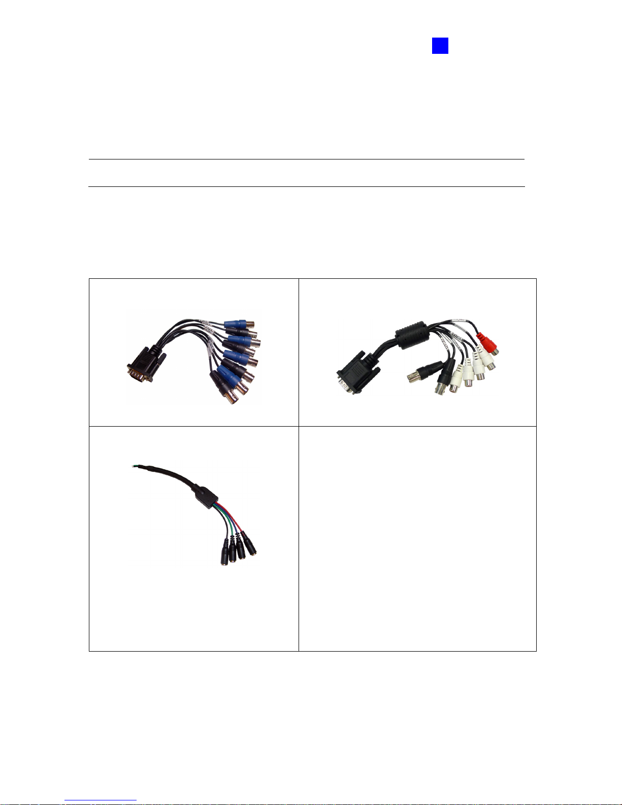
1.3.1 The Four-Channel Unit
• Standard Models (GV-LX4C3D1 / GV-LX4C3D2 / GV-LX4C3D2W)
• D-Type Video Cable x 1 • D-Type Audio/TV/Spot Monitor Cable x 1
• Camera Power Cable x 1
• Power Adaptor 12V, 5A x 1
• AC Power Cord x 1
• Lock Key x 2 (1 Bay), x 4 (2 Bays)
• Round Screws x 6 (1 Bay), x 12 (2 Bays)
• T-Cap Screw x 4 (1 Bay), x 8 (2 Bays)
• Remote Control x 1
• GV-Compact DVR Quick Start Guide x 1
• GV-Compact DVR Software DVD x 1
• GV-NVR Quick Start Guide x 1
• GV-NVR Software DVD x 1
Page 15
6
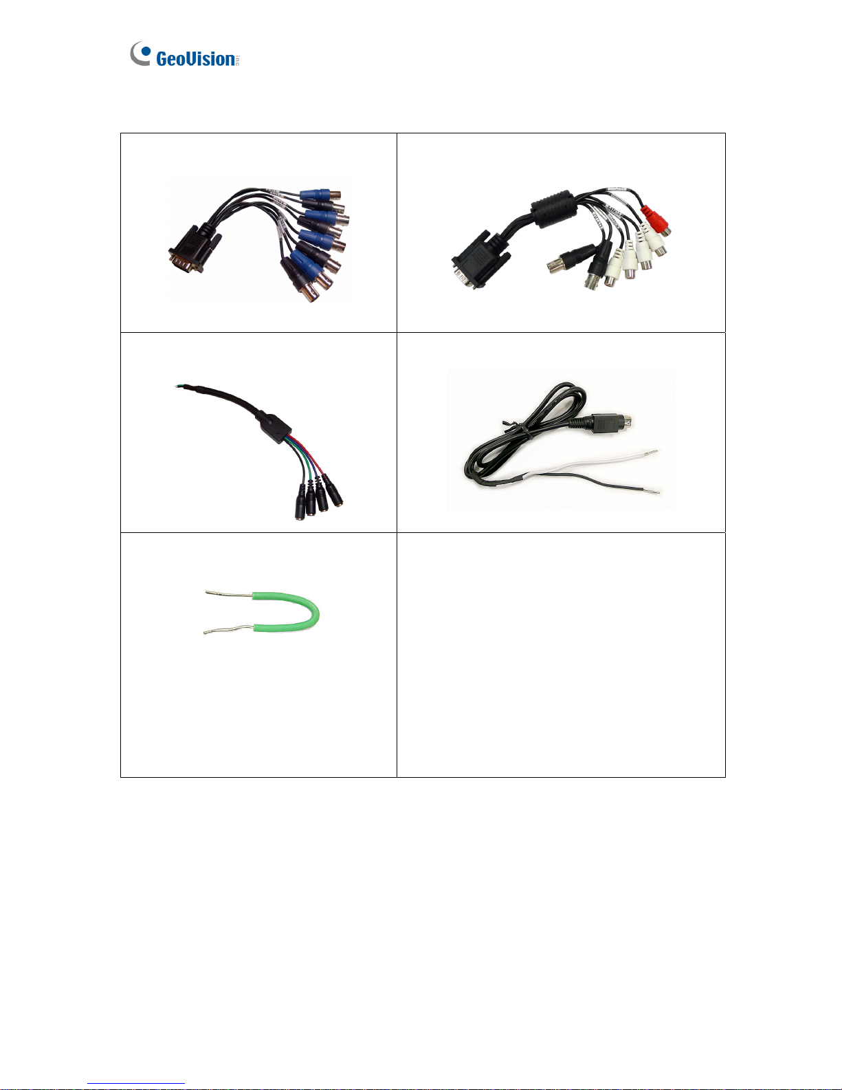
• Anti-Vibration ACC Model (GV-LX4C3V)
• D-Type Video Cable x 1 • D-Type Audio/TV/Spot Monitor Cable x 1
• Camera Power Cable x 1 • Power Cable x 1
• Shorting Cable x 1
• Lock Key x 2 (1 Bay), x 4 (2 Bays)
• Round Screws x 6 (1 Bay), x 12 (2 Bays)
• T-Cap Screw x 4 (1 Bay), x 8 (2 Bays)
• Remote Control x 1
• GV-Compact DVR Quick Start Guide x 1
• GV- Compact DVR Software DVD x 1
• GV-NVR Quick Start Guide x 1
• GV-NVR Software DVD x 1
Page 16
Introduction
7
1
1.3.2 The Eight-Channel Unit
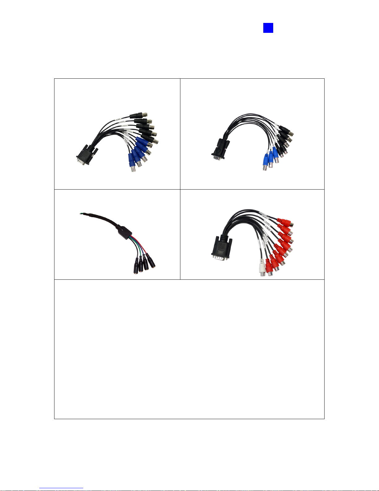
• Standard Models (GV-LX8CD1 / GV-LX8CD2 / GV-LX8CD2W)
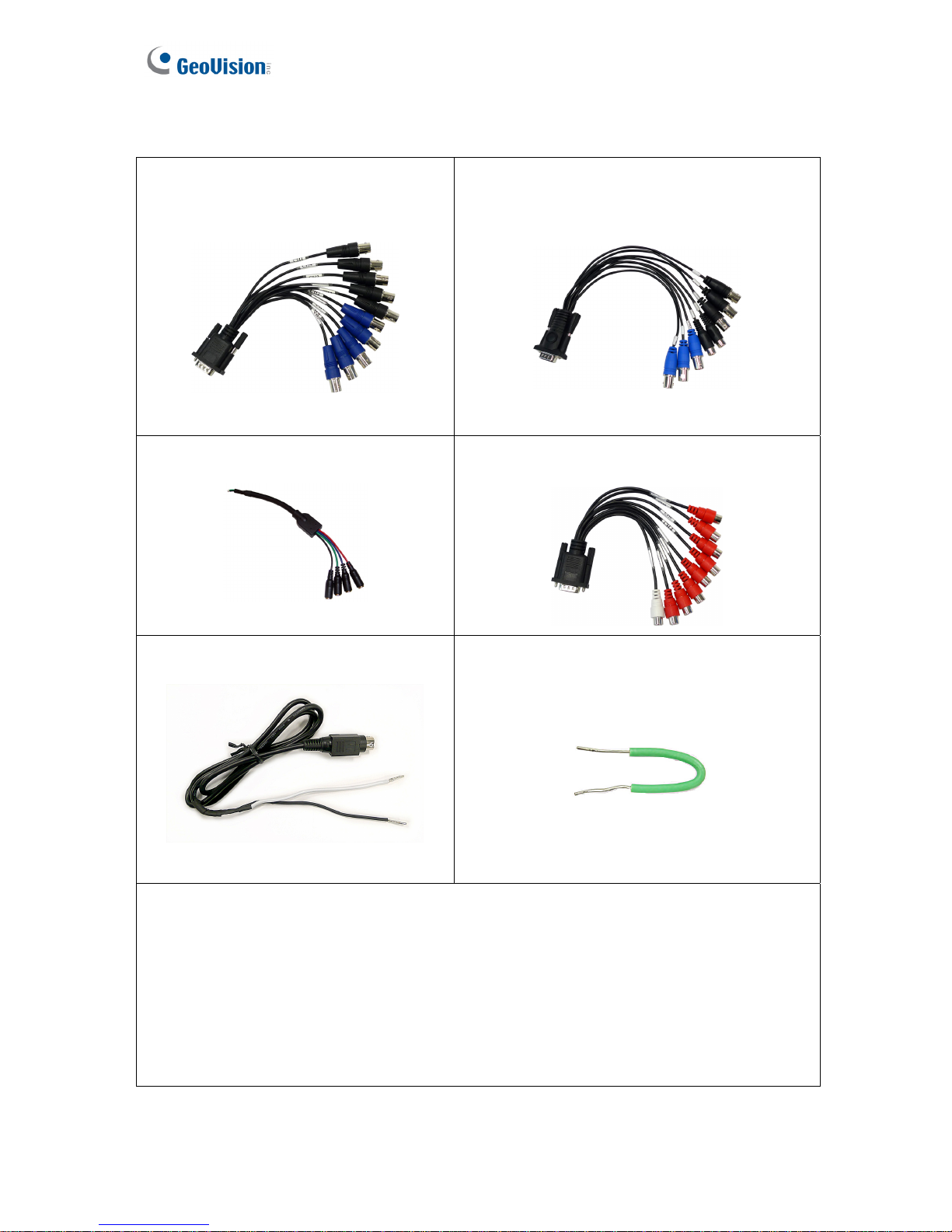
• 1 to 5 D-Type Video Cable x 1 • 6 to 8 D-Type Video/TV/Spot Monitor Cable
x 1
• Camera Power Cable x 2 • D-Type Audio Cable x 1
• Power Adaptor 12V, 5A x 1
• AC Power Cord x 1
• Lock Key x 2 (1 Bay), x 4 (2 Bays)
• Round Screws x 6 (1 Bay), x 12 (2 Bays)
• T-Cap Screw x 4 (1 Bay), x 8 (2 Bays)
• Remote Control x 1
• GV-Compact DVR Quick Start Guide x 1
• GV-Compact DVR Software DVD x 1
• GV-NVR Quick Start Guide x 1
• GV-NVR Software DVD x 1
Page 17
8
• Anti-Vibration ACC Models (GV-LX8CV1 / GV-LX8CV2)
• 1 to 5 D-Type Video Cable x 1 • 6 to 8 D-Type Video/ TV/ Spot Monitor
Cable x 1
• Camera Power Cable x 2 • D-Type Audio Cable x 1
• Power Cable x 1 • Shorting Cable x 1
• Lock Key x 2 (1 Bay), x 4 (2 Bays)
• Round Screws x 6 (1 Bay), x 12 (2
Bays)
• T-Cap Screw x 4 (1 Bay), x 8 (2
Bays)
• Remote Control x 1
• GV-Compact DVR Quick Start Guide x 1
• GV- Compact DVR Software DVD x 1
• GV-NVR Quick Start Guide x 1
• GV-NVR Software DVD x 1
Page 18
Introduction
9
1
1.4 Options
Optional devices can expand your GV-Compact DVR V3’s capabilities and versatility. Contact
your dealer for more information.
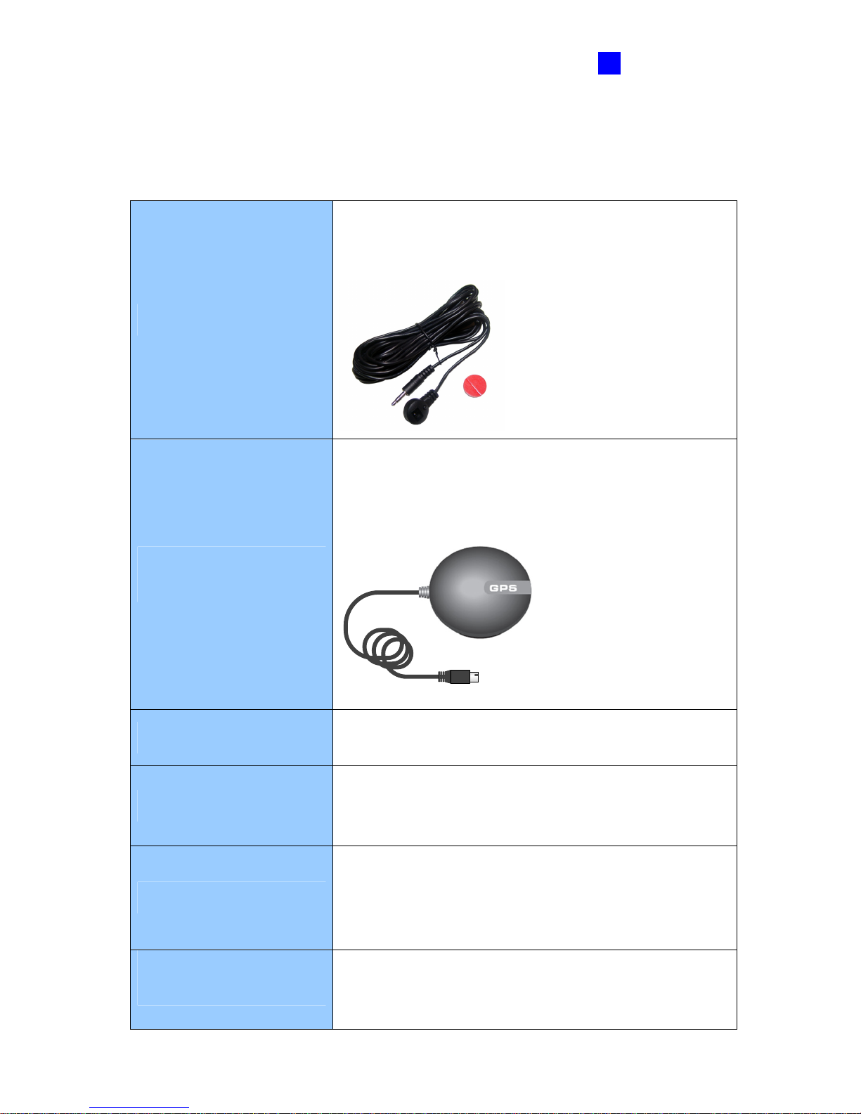
External IR Receiver
The external IR receiver, with a 5-meter cable (16.4 feet),
allows long-distance remote control of the GV-Compact DVR
V3.
GV-GPS 232 Receiver with
PS/2 Connector
GV-GPS 232 Receiver, with RS-232 interface, is a Global
Position System receiver. It can be applied to vehicle
tracking and location verification. The device is designed for
Anti-Vibration ACC models only.
2.5” to 3.5” HDD Converter
The HDD converter allows you to install a 2.5’’ SATA HDD
into GV-Compact DVR V3.
GV-Relay V2
Working with the GV-Relay V2, GV-Compact DVR V3 can
expand the voltage load up to 10A 250V AC / 10A 125V AC /
5A 100V DC.
WiFi USB Adaptor
The WiFi USB Adaptor is designed to connect the GV IP
devices, such as GV-Video Servers or GV-Compact DVRs,
to the wireless network. This product complies with IEEE
802.11 b/g/n (Draft 3.0) standards for wireless networking.
Power Adaptor of DC 12V,
5A
The power adaptor is used to power on the Anti-Vibration
ACC model to test the connection. This device is designed
for Anti-Vibration ACC models only.
Page 19

10
1.5 System Requirement
To access the Web interface of the GV-Compact DVR V3, it is required to use Microsoft
Internet Explorer 7.x or later.
Note: If you are using Microsoft Internet Explorer 8, additional settings are required. See
Setting for Internet Explorer 8 in Appendix C.
Page 20
Physical Description
11
2
Chapter 2 Physical Description
This section identifies the various components of the GV-Compact DVR V3, and provides the
overview of the remote control.
2.1 Front Panel
2.1.1 The Four-Channel Unit
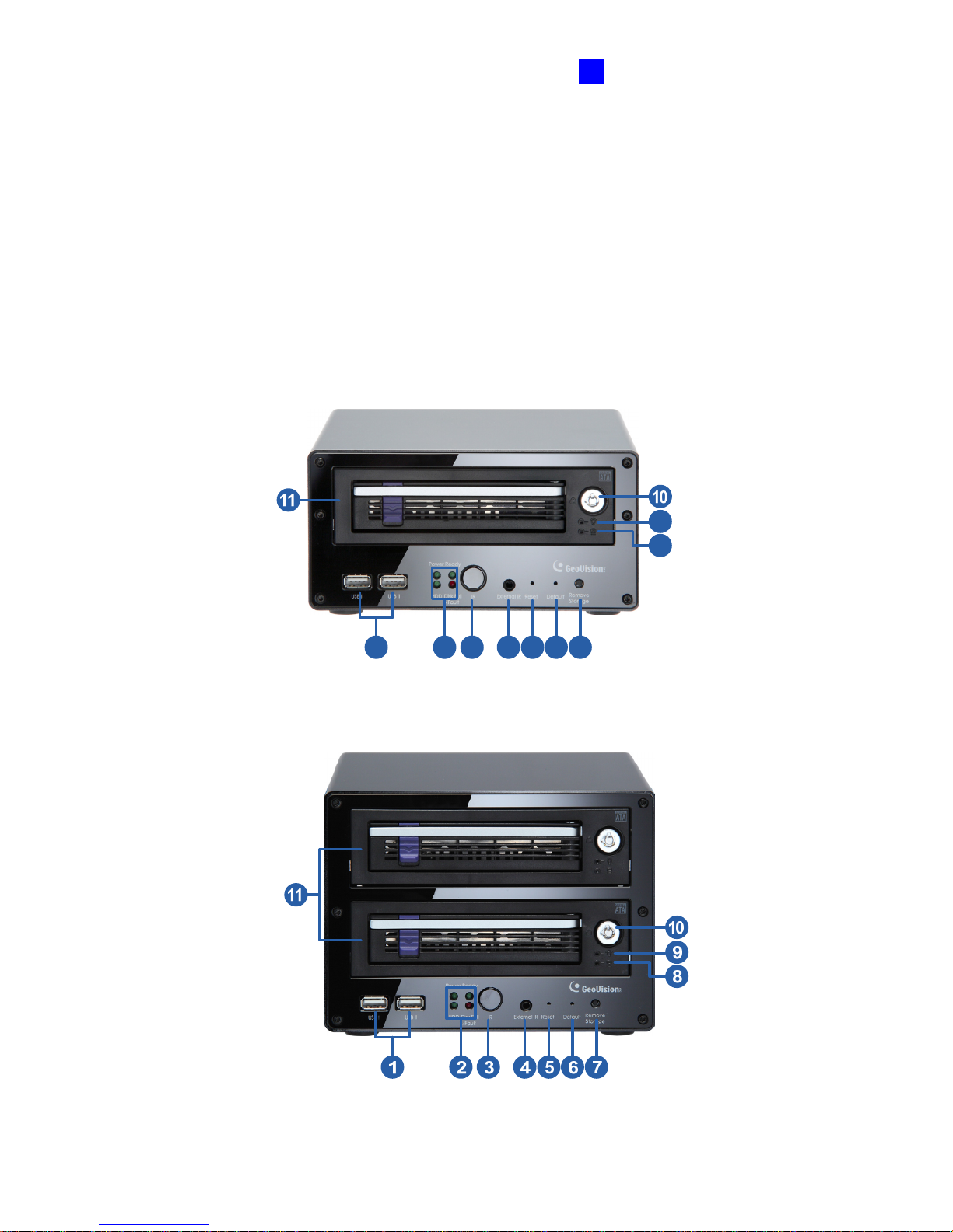
• Standard Models (GV-LX4C3D1 / GV-LX4C3D2 / GV-LX4C3D2W)
1. GV-LX4C3D1
1 2 3 4 5 6 7
8
9
Figure 2-1
2. GV-LX4C3D2
Figure 2-2
Page 21
12
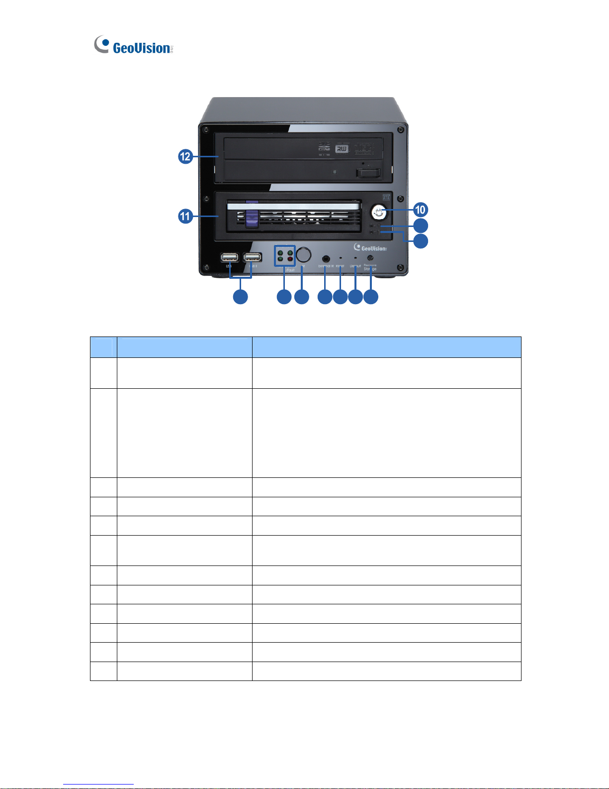
3. GV-LX4C3D2W
1 2 3 4 5 6 7
8
9
Figure 2-3
No. Name
Description
1 USB Port
The two USB ports can connect the USB storage device,
Wireless LAN adaptor and/or mobile Internet device.
2 System LED
• Power LED: Turns on when the power is supplied.
• Ready LED: Turns on when the unit is ready for use.
• HDD LED: Turns on when the HDD is reading or
writing data.
• Disk Full/ Fault LED: Turns on when the HDD is full
or read/write error occurs..
3 IR Receiver
Receives data from the infrared remote control.
4 External IR
Connects to an optional External IR Receiver.
5 Reset Button
Restarts the unit, and keeps all current configurations.
6 Default Button
Sets all configurations to their factory settings. See 8.4
Restoring to Factory Default Settings.
7 Storage Removal Button
Stops recording and detaches the HDD from the system.
8 HDD Activity LED
Blinks when the HDD is reading or writing data.
9 HDD Power LED
Turns on when the power is supplied.
10 Key Lock
Locks and unlocks the HDD drive bay.
11 HDD Drive Bay
Installs the SATA hard drive for recording.
12 DVD-RW Drive
Writes the DVD disc for data backup.
Page 22
Physical Description
13
2
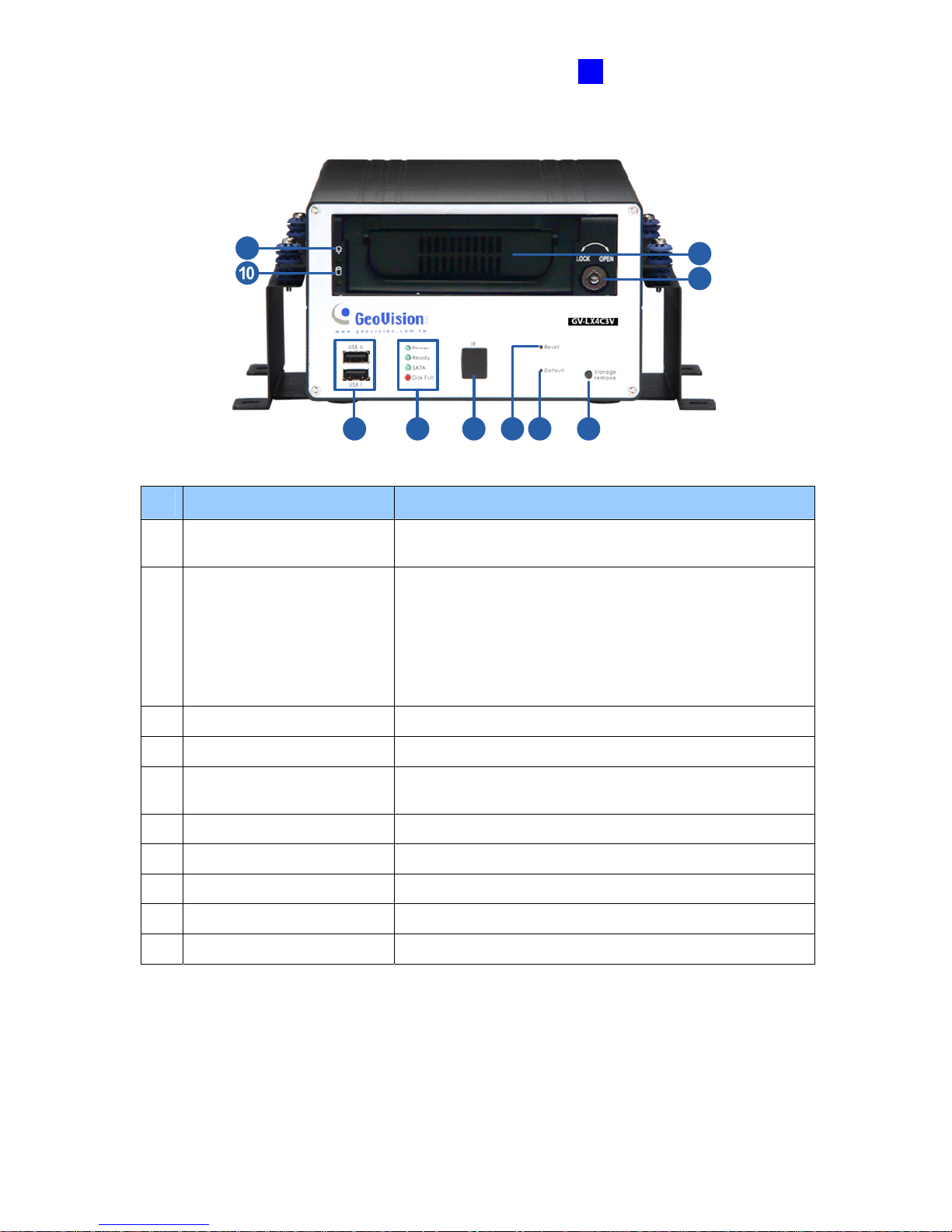
• The Anti-Vibration ACC Model (GV-LX4C3V)
1 4 5 62 3
7
8
9
Figure 2-4
No. Name
Description
1 USB Port
The two USB ports can connect the USB storage device,
Wireless LAN adaptor and/or mobile Internet device.
2 System LED
• Power LED: Turns on when the power is supplied.
• Ready LED: Turns on when the unit is ready for use.
• SATA LED: Turns on when the HDD is reading or
writing data.
• Disk Full LED: Turns on when the HDD is full or
read/write error occurs.
3 IR Receiver
Receives data from the infrared remote control.
4 Reset Button
Restarts the unit, and keeps all current configurations.
5 Default Button
Sets all configurations to their factory settings. See 8.4
Restoring to Factory Default Settings.
6 Storage Removal Button
Stops recording and detaches the HDD from the system.
7 Key Lock
Locks and unlocks the HDD drive bay.
8 HDD Drive Bay
Installs the SATA hard drive for recording.
9 HDD Power LED
Turns on when the power is supplied.
10 HDD Activity LED
Blinks when the HDD is reading or writing data.
Page 23
14
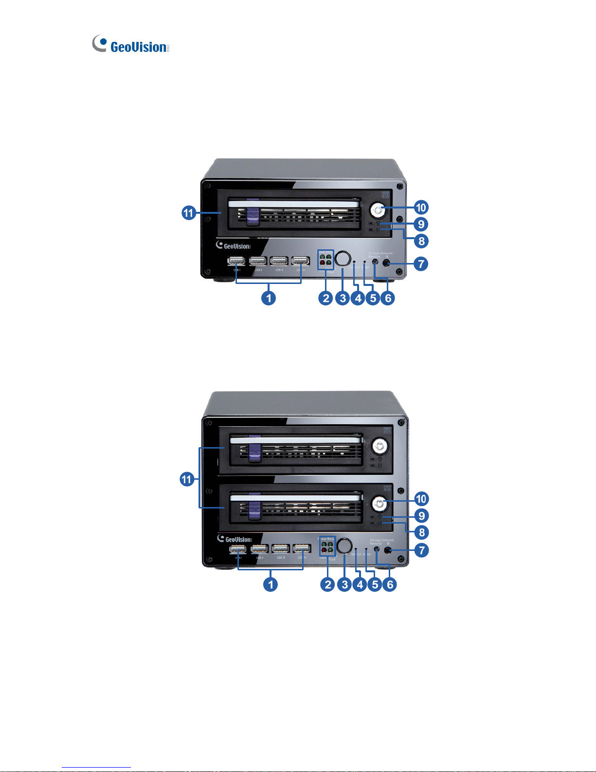
2.1.2 The Eight-Channel Unit
• Standard Models (GV-LX8CD1 / GV-LX8CD2 / GV-LX8CD2W)
1. GV-LX8CD1
Figure 2-5
2. GV-LX8CD2
Figure 2-6
Page 24
Physical Description
15
2
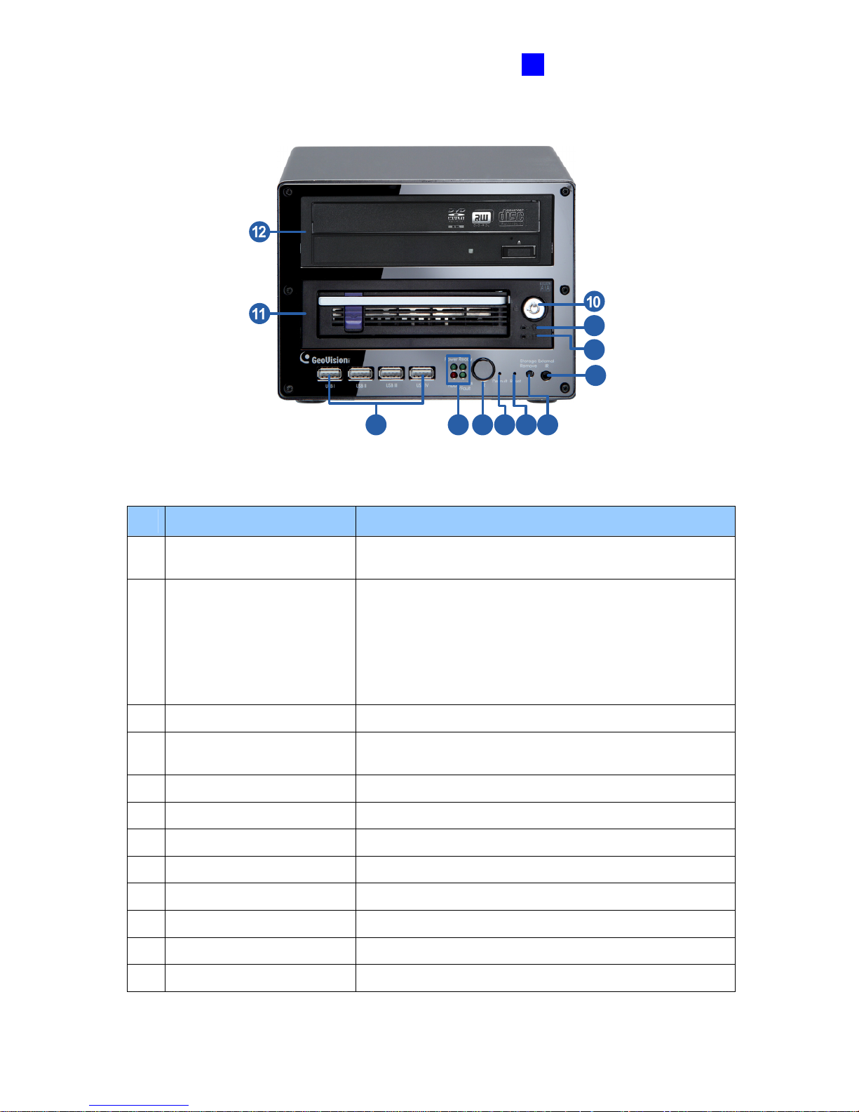
3. GV-LX8CD2W
1 2 3 4 5 6
7
8
9
Figure 2-7
No. Name
Description
1 USB Port
The four USB ports can connect the USB storage device,
Wireless LAN adaptor and/or mobile Internet device.
2 System LED
• Power LED: Turns on when the power is supplied.
• Ready LED: Turns on when the unit is ready for use.
• HDD LED: Turns on when the HDD is reading or
writing data.
• Disk Full / Fault LED: Turns on when the HDD is full
or read/write error occurs.
3 IR Receiver
Receives data from the infrared remote control.
4 Default Button
Sets all configurations to their factory settings. See 8.4
Restoring to Factory Default Settings.
5 Reset Button
Restarts the unit, and keeps all current configurations.
6 Storage Removal Button
Stops recording and detaches the HDD from the system.
7 External IR
Connects to an optional External IR Receiver.
8 HDD Activity LED
Blinks when the HDD is reading or writing data.
9 HDD Power LED
Turns on when the power is supplied.
10 Key Lock
Locks and unlocks the HDD drive bay.
11 HDD Drive Bay
Installs the SATA hard drive for recording.
12 DVD-RW Drive
Writes the DVD disc for data backup.
Page 25
16
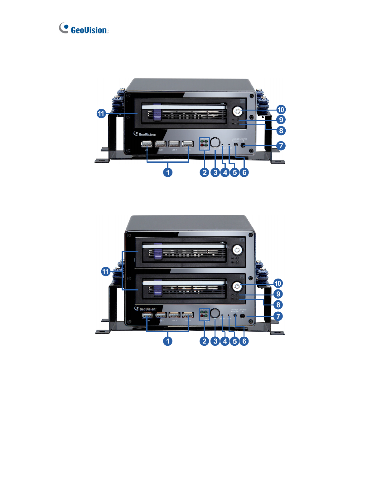
• Anti-Vibration ACC Models (GV-LX8CV1 / GV-LX8CV2)
1. GV- GV-LX8CV1
Figure 2-8
2. GV- GV-LX8CV2
Figure 2-9
Page 26
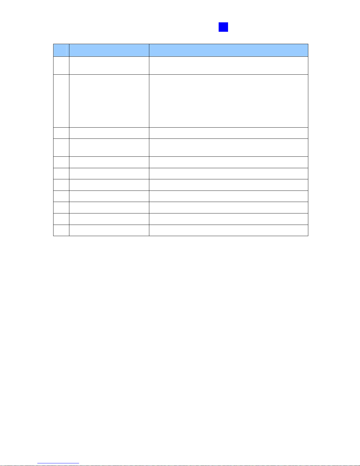
Physical Description
17
2
No. Name
Description
1 USB Port
The four USB ports can connect the USB storage device,
Wireless LAN adaptor and/or mobile Internet device.
2 System LED
• Power LED: Turns on when the power is supplied.
• Ready LED: Turns on when the unit is ready for use.
• HDD LED: Turns on when the HDD is reading or
writing data.
• Disk Full / Fault LED : Turns on when the HDD is
full or read/write error occurs.
3 IR Receiver
Receives data from the infrared remote control.
4 Default Button
Sets all configurations to their factory settings. See 8.4
Restoring to Factory Default Settings.
5 Reset Button
Restarts the unit, and keeps all current configurations.
6 Storage Removal Button
Stops recording and detaches the HDD from the system.
7 External IR
Connects to an optional External IR Receiver.
8 HDD Activity LED
Blinks when the HDD is reading or writing data.
9 HDD Power LED
Turns on when the power is supplied.
10 Key Lock
Locks and unlocks the HDD drive bay.
11 HDD Drive Bay
Installs the SATA hard drive for recording.
Page 27
18
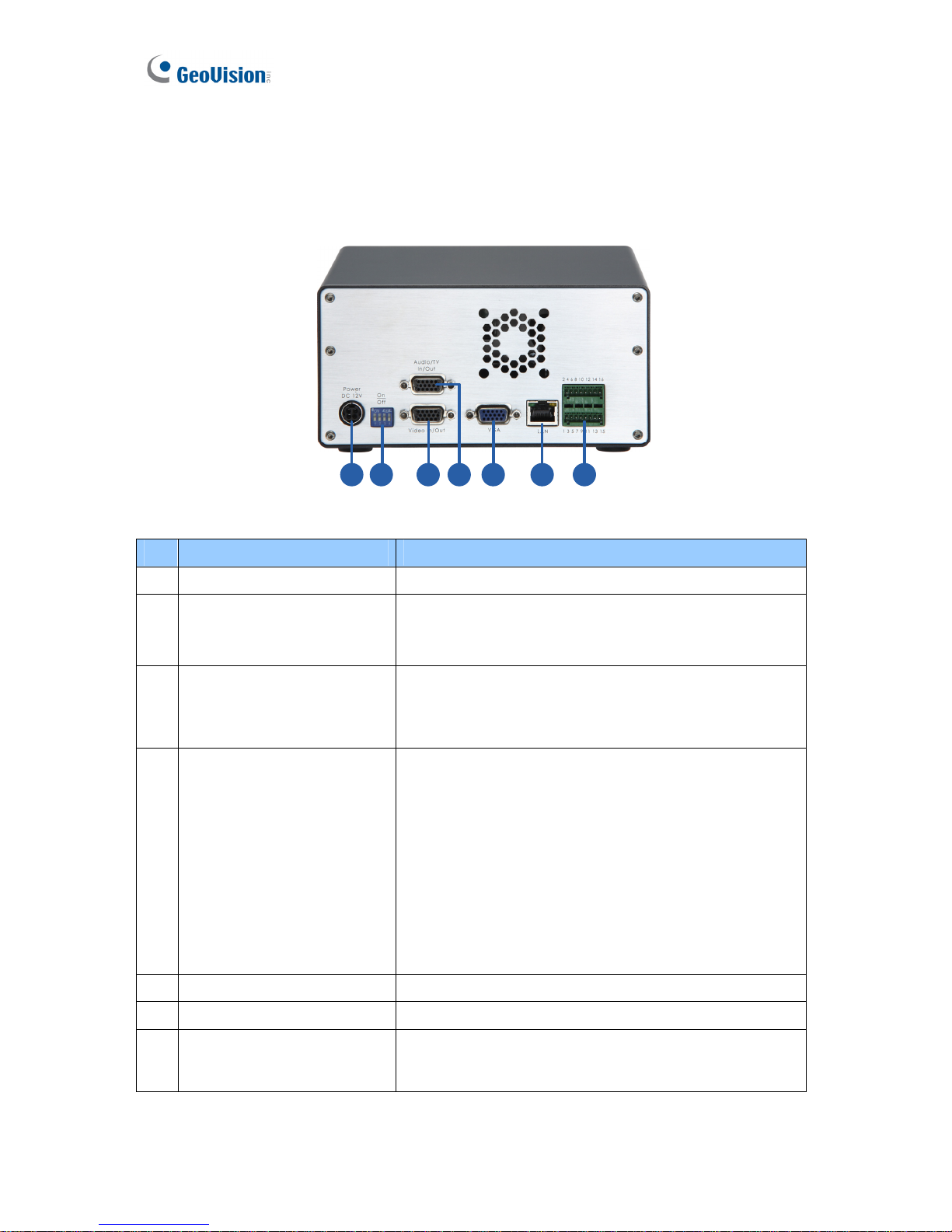
2.2 Rear Panel
2.2.1 The Four-Channel Unit
• Standard Models (GV-LX4C3D1 / GV-LX4C3D2 / GV-LX4C3D2W)
1 2 3 4 5 6 7
Figure 2-10
No. Name
Description
1 DC Power Input (12V)
Connects to power supply.
2 75 Ω
When using the Loop function, turn the switches to OFF
positions. The switch number is corresponding to the
channel number. The default setting is ON.
3 Video In/Out
• Inputs (4 Blue Connectors/CH1-4): Connects to
cameras.
• Outputs (4 Black Connectors/CH1-4): Loops out
each camera input to monitors.
4 Audio/TV In/Out
• TV Output (1 Black Connector/QUAD): Connects
to a TV monitor.
• Spot Monitor Output (1 Black Connector/MUX):
Connects to a spot monitor to display video
sequentially from each video input.
• Audio Inputs (4 White Connectors/CH1-4):
Connects to microphones.
• Audio Output for playback (1 Red Connector/
AUD-OUT): Connects to speakers. Note the audio
output only works during playback or when
receiving callback audio.
5 VGA Monitor Port
Connects to a PC monitor.
6 LAN Port
Connects to the network.
7 I/O Terminal Block
Connects to input and output devices, PTZ cameras,
and etc. For details see Chapter 12 The I/O Terminal
Block.
Page 28
Physical Description
19
2
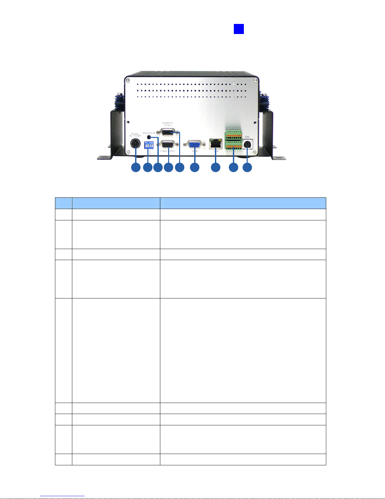
• The Anti-Vibration ACC Model (GV-LX4C3V)
1 2 4 5 6 7 83 9
Figure 2-11
No. Name
Description
1 DC Power Input (12V)
Connects to power supply.
2 75 Ω
When using the Loop function, turn the switches to OFF
positions. The switch number is corresponding to the
channel number. The default setting is ON.
3 External IR
Connects to an optional External IR Receiver.
4 Video In/Out
• Inputs (4 Blue Connectors/CH1-4): Connects to
cameras.
• Outputs (4 Black Connectors/CH1-4): Loops out
each camera input to monitors.
5 Audio/TV In/Out
• TV Output (1 Black Connector/QUAD): Connects
to a TV monitor.
• Spot Monitor Output (1 Black Connector/MUX):
Connects to a spot monitor to display video
sequentially from each video input.
• Audio Inputs (4 White Connectors/CH1-4):
Connects to microphones.
• Audio Output for playback (1 Red Connector/
AUD-OUT): Connects to speakers. Note the audio
output only works during playback or when
receiving callback audio.
6 VGA Monitor Port
Connects to a PC monitor.
7 LAN Port
Connects to the network.
8 I/O Terminal Block
Connects to input and output devices, PTZ cameras
and etc. For details see Chapter 12 The I/O Terminal
Block.
9 GPS Port (PS/2 Connector)
Connects to a GPS 232 receiver.
Page 29
20
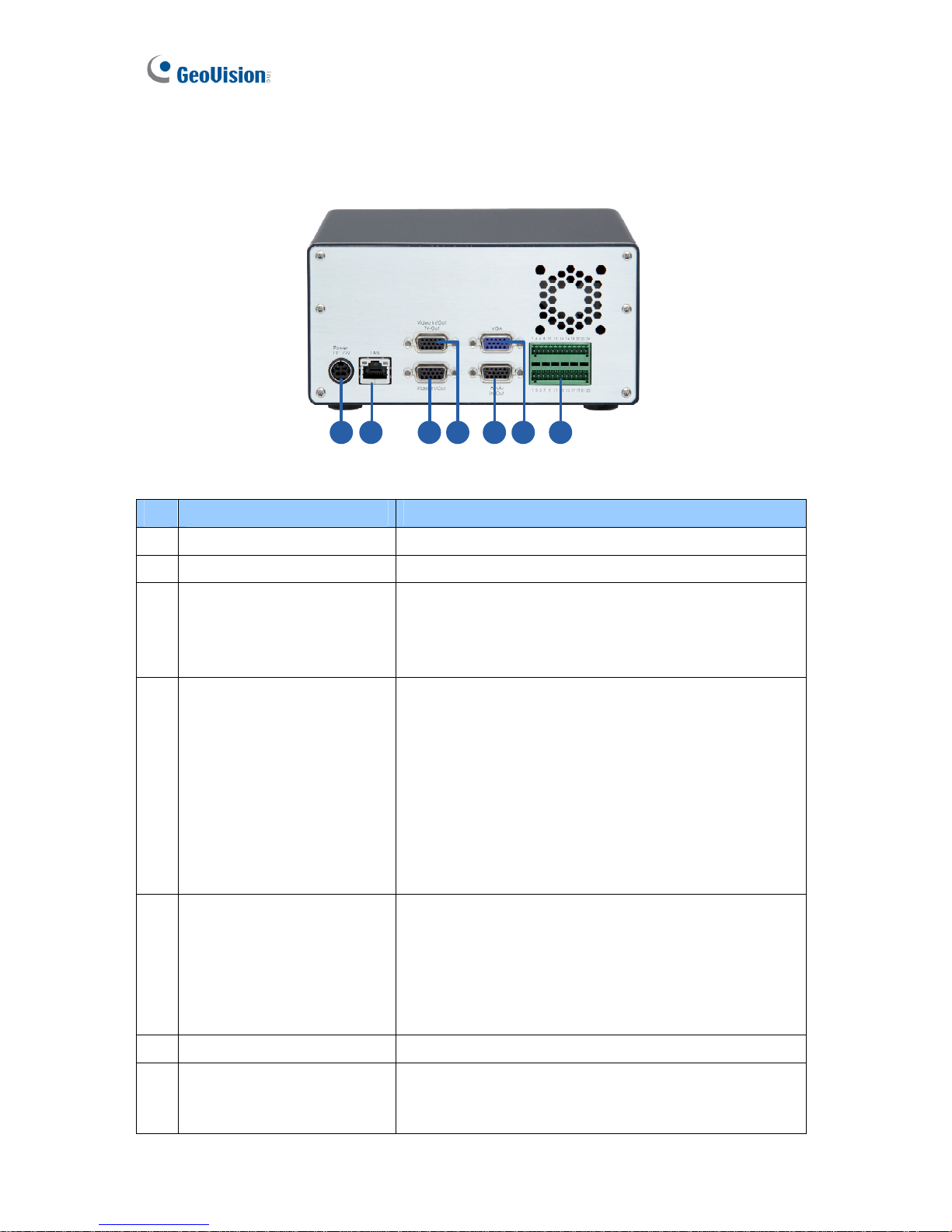
2.2.2 The Eight-Channel Unit
• Standard Models (GV-LX8CD1 / GV-LX8CD2 / GV-LX8CD2W)
1 2 3 4 5 76
Figure 2-12
No. Name
Description
1 DC Power Input (12V)
Connects to power supply.
2 LAN Port
Connects to the network.
3
Video In/Out
• Inputs (5 Blue Connectors/CH1-5): Connects to
cameras.
• Outputs (5 Black Connectors/CH1-5): Loops out
each camera input to monitors.
4
Video In/Out & TV-Out
• Inputs (3 Blue Connectors/CH6-8): Connects to
cameras.
• Outputs (3 Black Connectors/CH6-8): Loops out
each camera input to monitors.
• TV Output (1 Black Connector/QUAD): Connects
to a TV monitor.
• Spot Monitor Output (1 Black Connector/MUX):
Connects to a spot monitor to display video
sequentially from each video input.
5 Audio In/Out
• Audio Inputs (8 Red Connectors/CH1-8):
Connects to microphones.
• Audio Output for playback (1 White Connector/
AUD-OUT): Connects to speakers. Note the audio
output only works during playback or when
receiving callback audio.
6 VGA Monitor Port
Connects to a PC monitor.
7 I/O Terminal Block
Connects to input and output devices, PTZ cameras
and etc. For details see Chapter 12 The I/O Terminal
Block.
Page 30
Physical Description
21
2
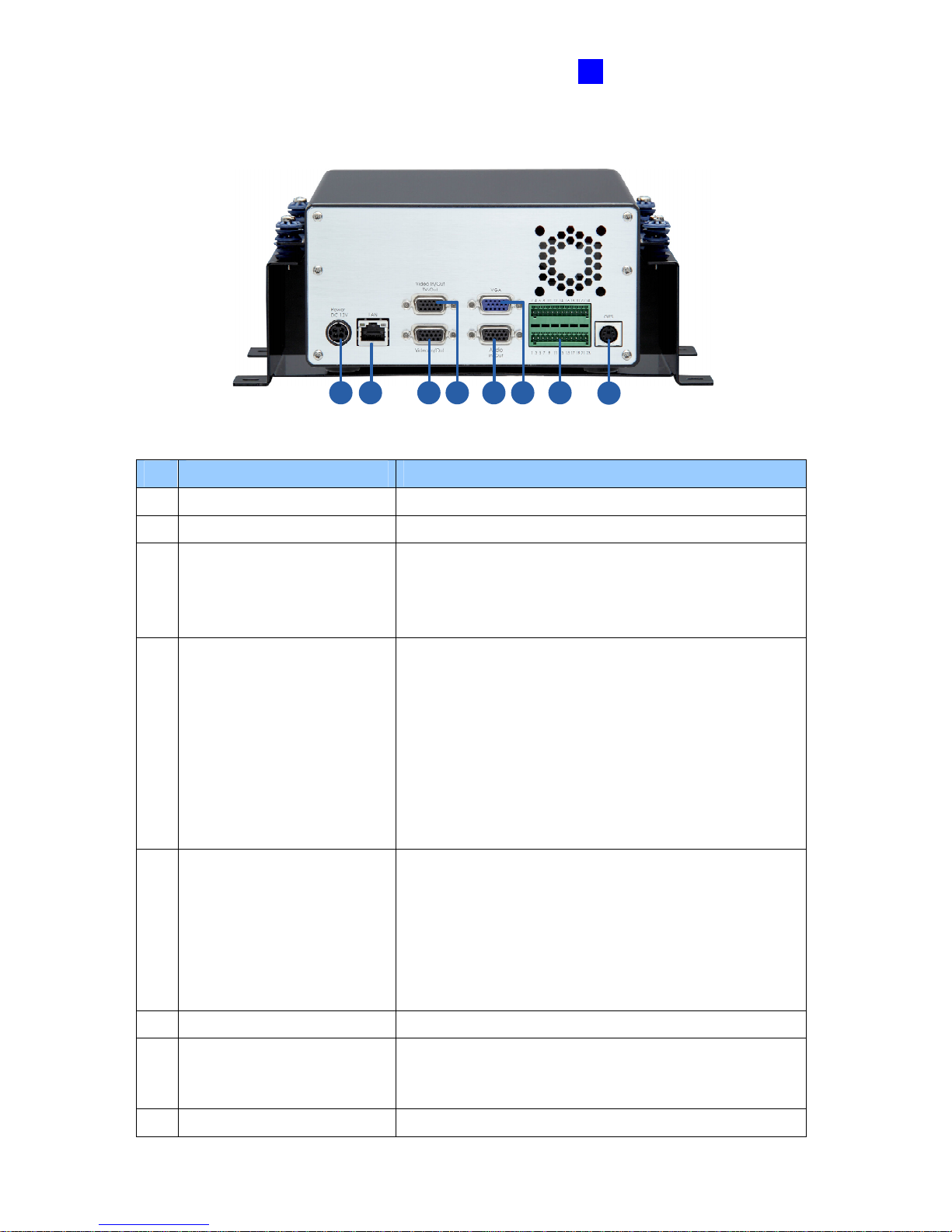
• Anti-Vibration ACC Models (GV-LX8CV1 / GV-LX8CV2)
1 2 3 4 5 76
8
Figure 2-13
No. Name
Description
1 DC Power Input (12V)
Connects to power supply.
2 LAN Port
Connects to the network.
3 Video In/Out
• Inputs (5 Blue Connectors/CH1-5): Connects to
cameras.
• Outputs (5 Black Connectors/CH1-5): Loops out
each camera input to monitors.
4 Video In/Out TV-Out
• Inputs (3 Blue Connectors/CH6-8): Connects to
cameras.
• Outputs (3 Black Connectors/CH6-8): Loops out
each camera input to monitors.
• TV Output (1 Black Connector/QUAD): Connects
to a TV monitor.
• Spot Monitor Output (1 Black Connector/MUX):
Connects to a spot monitor to display video
sequentially from each video input.
5
Audio In/Out
• Audio Inputs (8 Red Connectors/CH1-8):
Connects to the microphone.
• Audio Output for playback (1 White Connector/
AUD-OUT): Connects to speakers. Note the audio
output only works during playback or when
receiving callback audio.
6 VGA Monitor Port
Connects to a PC monitor.
7 I/O Terminal Block
Connects to input and output devices, PTZ cameras
and etc. For details see Chapter 12 The I/O Terminal
Block.
8 GPS Port (PS/2 Connector)
Connects to a GPS 232 receiver.
Page 31
22
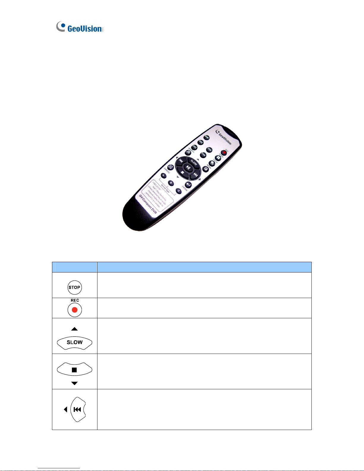
2.3 Remote Control
The GV-Compact DVR V3 Remote Control is provided to configure and operate the
GV-Compact DVR V3.
2.3.1 The Four-Channel Unit
Figure 2-14
Button Description
Stops recording.
Starts recording.
OSD menu: Moves the focus upward to the desired item.
Playback: Decreases the speed of playback.
OSD menu: Moves the focus downward to the desired item.
Playback: Stops playback.
OSD menu: Moves the focus leftward to the desired item; moves to the
previous page.
Playback: Plays the video backward at different speeds (2x, 4x, 8x, 16x and
32x).
Page 32
Physical Description
23
2
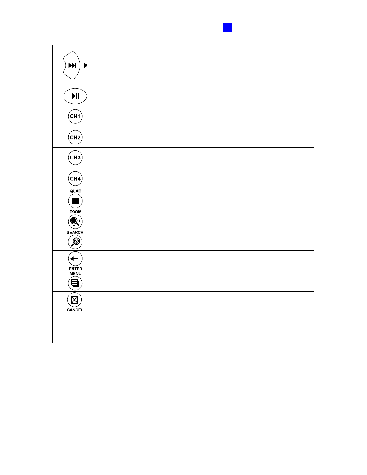
OSD menu: Moves the focus rightward to the desired item; moves to the
next page.
Playback: Plays the video forward at different speeds (2x, 4x, 8x, 16x and
32x).
OSD menu: Enters the menu option and confirms the selection.
Playback: Plays or pauses video.
Switches to Channel 1 or I/O device 1.
Switches to Channel 2 or I/O device 2.
Switches to Channel 3 or I/O device 3.
Switches to Channel 4 or I/O device 4.
Switches to the screen of 4 divisions.
Zooms in or out.
Calls up the menu of SEARCH/PLAYBACK.
Confirms the menu selection.
Calls up the main menu.
Quits the menu selection or exits the menu.
A / B / C
Device Type
Switches among up to 3 units of GV-Compact DVR V3 for remote control. To
set the device type of the GV-Compact DVR V3, see IR TYPE, 4.8.4 Display
Settings.
Page 33
24
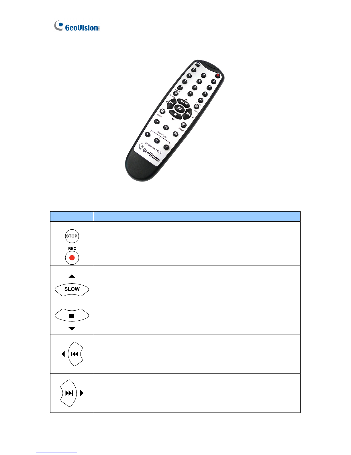
2.3.2 The Eight-Channel Unit
Figure 2-15
Button Description
Stops recording.
Starts recording.
OSD menu: Moves the focus upward to the desired item.
Playback: Decreases the speed of playback.
OSD menu: Moves the focus downward to the desired item.
Playback: Stops playback.
OSD menu: Moves the focus leftward to the desired item; moves to the
previous page.
Playback: Plays the video backward at different speeds (2x, 4x, 8x, 16x and
32x).
OSD menu: Moves the focus rightward to the desired item; moves to the
next page.
Playback: Plays the video forward at different speeds (2x, 4x, 8x, 16x and
32x).
Page 34
Physical Description
25
2
OSD menu: Enters the menu option and confirms the selection.
Playback: Plays or pauses video.
to
Switches to Channel 1 to Channel 8 or I/O device 1 to 8.
Switches to the screen of 4 divisions.
Zooms in or out.
Calls up the menu of SEARCH/PLAYBACK.
Confirms the menu selection.
Calls up the main menu.
Quits the menu selection or exits the menu.
A / B / C
Device Type
Switches among up to 3 units of GV-Compact DVR V3 for remote control. To
set the device type of the GV-Compact DVR V3, see IR TYPE, 4.8.4 Display
Settings.
Page 35

26
Chapter 3 Getting Started
Getting started with the GV-Compact DVR V3 consists of the following steps:
3.1 Basic Connection for Standard Models
Install the video display devices.
3.2 Basic Connection for Anti-Vibration Models
Connect the unit to the vehicle.
3.3 Connecting Anti-Vibration ACC Models
Describe the ACC connection in detail.
3.4 Connecting Optional Video Output Devices
Connect optional video output devices.
3.5 Installing a Hard Drive
Install a hard drive for video recording.
3.6 Turning on and off the Power
Turn on and off the unit.
3.7 Formatting a Hard Drive
Format the hard drive before recording.
3.8 Main Screen Overview
Access the system information on the main screen.
3.9 Basic Operation
Page 36
Getting Started
27
3
3.1 Basic Connection for Standard Models
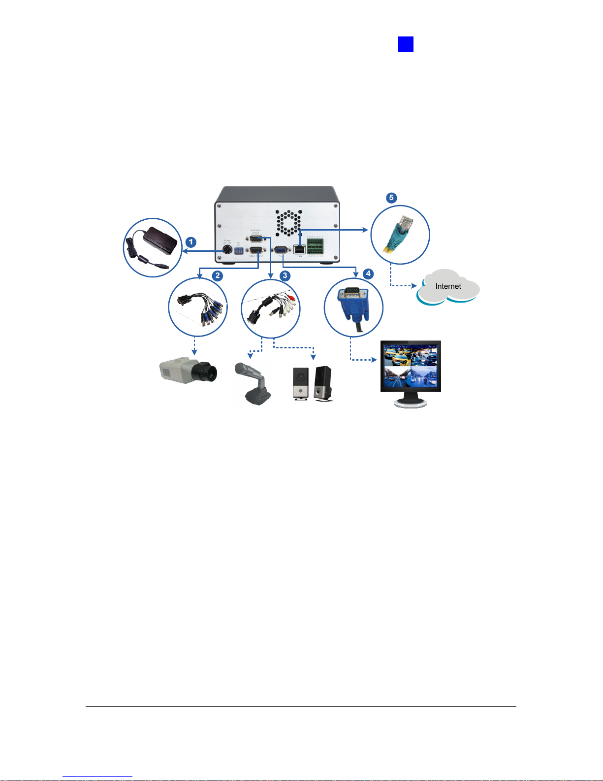
The following instructions describe the basic connection to the GV-Compact DVR V3.
3.1.1 The Four-Channel Unit
Figure 3-1
1. Use the supplied power adaptor to connect to power.
2. Connect to cameras by using the blue connectors of the supplied D-Type Video Cable.
3. Connect to microphones and a speaker by using the supplied D-Type Audio/TV/Spot
Monitor Cable. Connect microphones to the four white connectors of the cable, and a
speaker to the red connector.
4. Connect video output. There are two options:
• Using the black connector (QUAD) of the supplied D-Type Audio/TV/Spot Monitor
Cable, connect to a TV monitor.
• Using the VGA cable supplied by the monitor manufacturer, connect to a VGA
monitor (as illustrated in the figure).
5. Use the standard RJ-45 cable to connect the unit to the network.
Note:
1. To set the video resolution on the VGA monitor, see VGA SETTINGS, 4.8.4 Display
Settings.
2. The GV-Compact DVR V3 cannot work with the microphone that acquires power from the
unit. Use the microphone that has external power supply.
Page 37
28
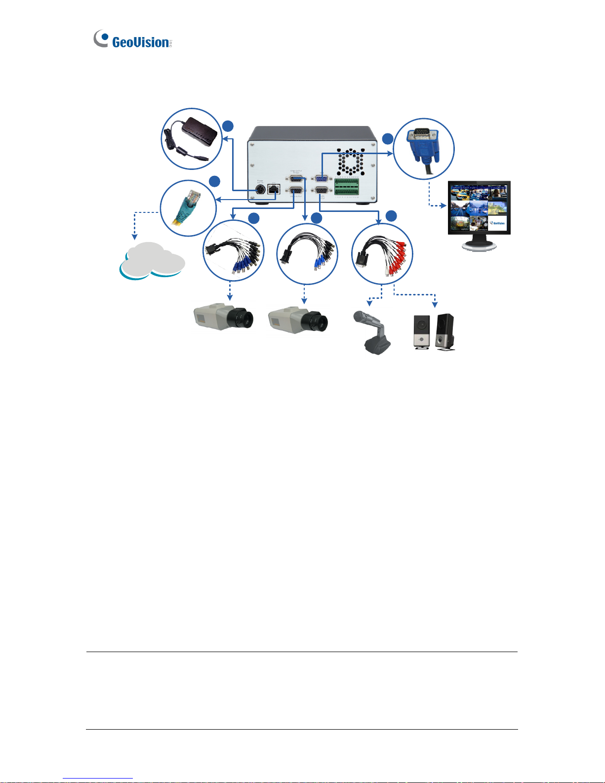
3.1.2 The Eight-Channel Unit
1
4
5
Internet
6
2
3
Figure 3-2
1. Use the supplied power adaptor to connect to power.
2. Connect to cameras (Camera 1 to 5) by using the blue connectors of the supplied 1 to 5
D-Type Video Cable.
3. Connect to cameras (Camera 6 to 8) by using the blue connectors of the supplied 6 to 8
D-Type Video/ TV/Spot Monitor Cable.
4. Connect to microphones and a speaker by using the supplied D-Type Audio Cable.
Connect microphones to the eight red connectors of the cable, and a speaker to the white
connector.
5. Connect video output. There are two options:
• Using the black connector (QUAD) of the supplied 6 to 8 D-Type Video/TV/Spot
Monitor Cable, connect to a TV monitor.
• Using the VGA cable supplied by the monitor manufacturer, connect to a VGA
monitor (as illustrated in the figure).
6. Use the standard RJ-45 cable to connect the unit to the network.
Note:
1. To set the video resolution on the VGA monitor, see VGA SETTINGS, 4.8.4 Display
Settings.
2. The GV-Compact DVR V3 cannot work with the microphone that acquires power from the
unit. Use the microphone that has external power supply.
Page 38
Getting Started
29
3
3.2 Basic Connection for Anti-Vibration Models
You need to connect the Anti-Vibration ACC model to ACC wire and power wire on the vehicle.
When the unit is connected to the ACC wire properly, it will automatically start after you power
on the vehicle for 5 seconds. After you power off the vehicle for 30 seconds, the unit will turn
off automatically. During the 30 seconds after power off, the GV-Compact DVR V3 will stop
recording and the hard drive will be removed from the system automatically.
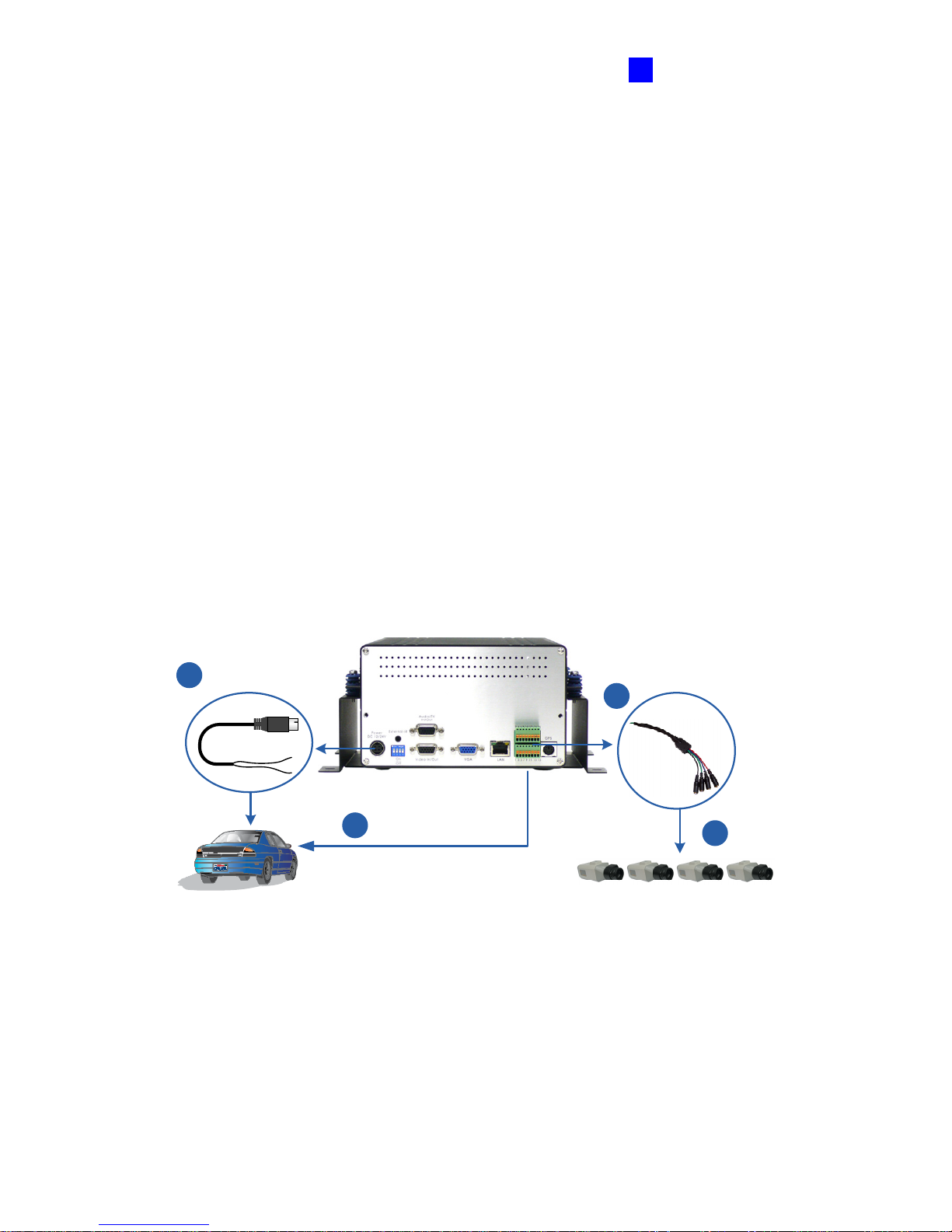
3.2.1 The Four-Channel Unit
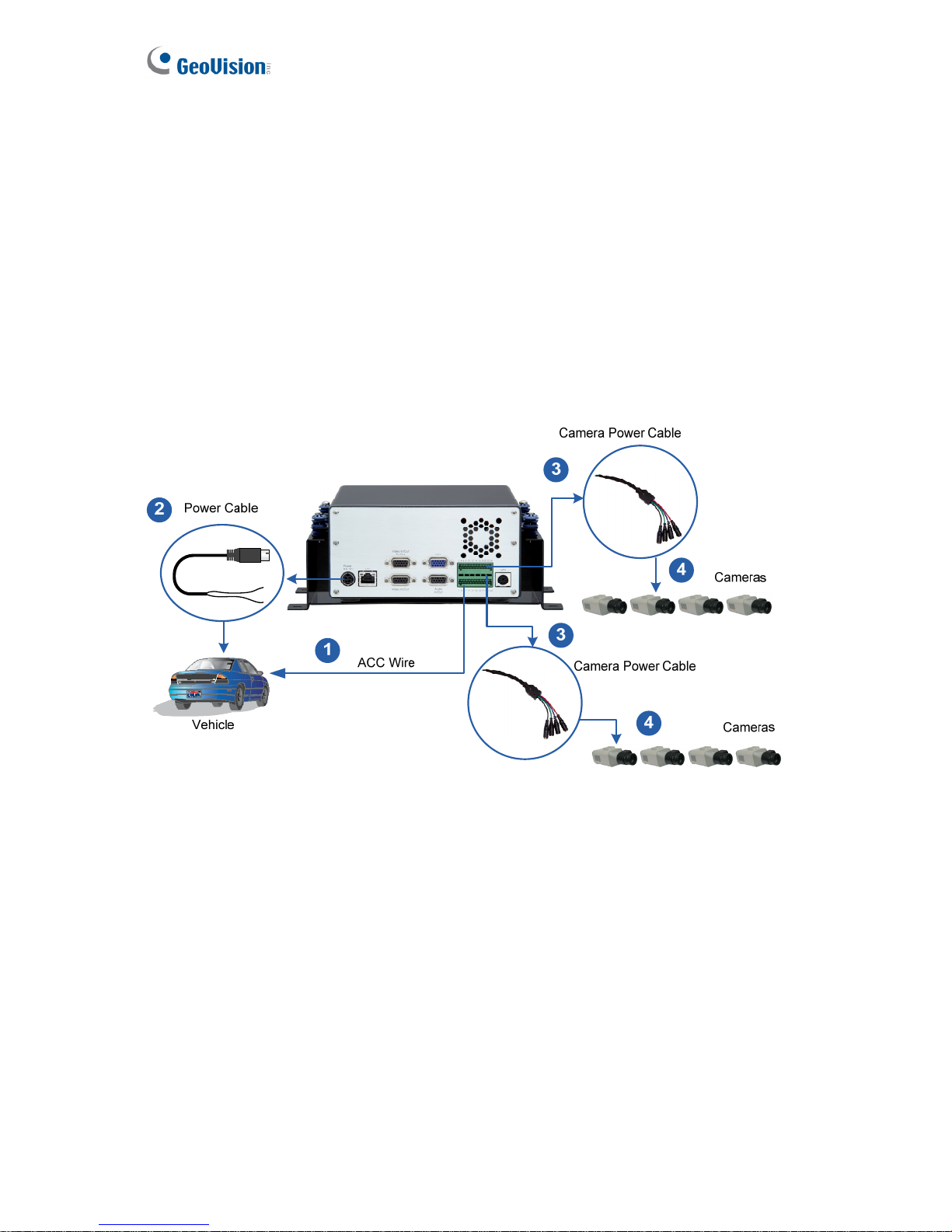
1. Connect the ACC wire from the vehicle to Pin 16 on the terminal Block. For details, see
Connecting the ACC Wire of 3.3.2 Connecting to a Vehicle.
2. Connect the Power Cable to the GV-Compact DVR V3 and to the vehicle. For details, see
Connecting the Power Wire of 3.3.2 Connecting to a Vehicle.
3. Connect the black wire of the Camera Power Cable to Pin 10 on the terminal block, and
red wire to Pin 11 on the terminal Block.
4. Connect the Camera Power Cable to up to four cameras.
Vehicle
ACC Wire
Cameras
Camera Power
Cable
Power Cable
1
2
3
4
Figure 3-3
Page 39
30
3.2.2 The Eight-Channel Unit
1. Connect the ACC wire from the vehicle to Pin 24 on the terminal block. For details, see
Connecting the ACC Wire of 3.3.2 Connecting to a Vehicle.
2. Connect the Power Cable to the GV-Compact DVR V3 and to the vehicle. For details, see
Connecting the Power Wire of 3.3.2 Connecting to a Vehicle.
3. Connect the black wires of the Camera Power Cables to Pin 18 and Pin 20 on the
terminal block; connect the red wires of the Camera Power Cables to Pin 17 and Pin 19
on the terminal block.
4. Connect the Camera Power Cables to up to eight cameras.
Figure 3-4
Page 40

Getting Started
31
3
3.3 Connecting Anti-Vibration ACC Models
You need to connect the Anti-Vibration ACC model to the ACC wire and power wire on the
vehicle. Before real deployment, it is suggested to test connection to the ACC wire and set up
the unit.
3.3.1 Connecting and Testing
Before you connect the Anti-Vibration ACC model to a vehicle, it is recommended to test and
set up the unit first by using the supplied Shorting Cable. The Shorting Cable is designed to
simulate the ACC wiring between the unit and the vehicle. For the test, you need to prepare a
power adaptor (DC 12V, 5.0A) to power on the unit. Follow the steps below.
Items required for testing:
z Supplied Shorting Cable
z Power Adaptor of DC 12V, 5A (which can be purchased from GeoVision)
Page 41
32
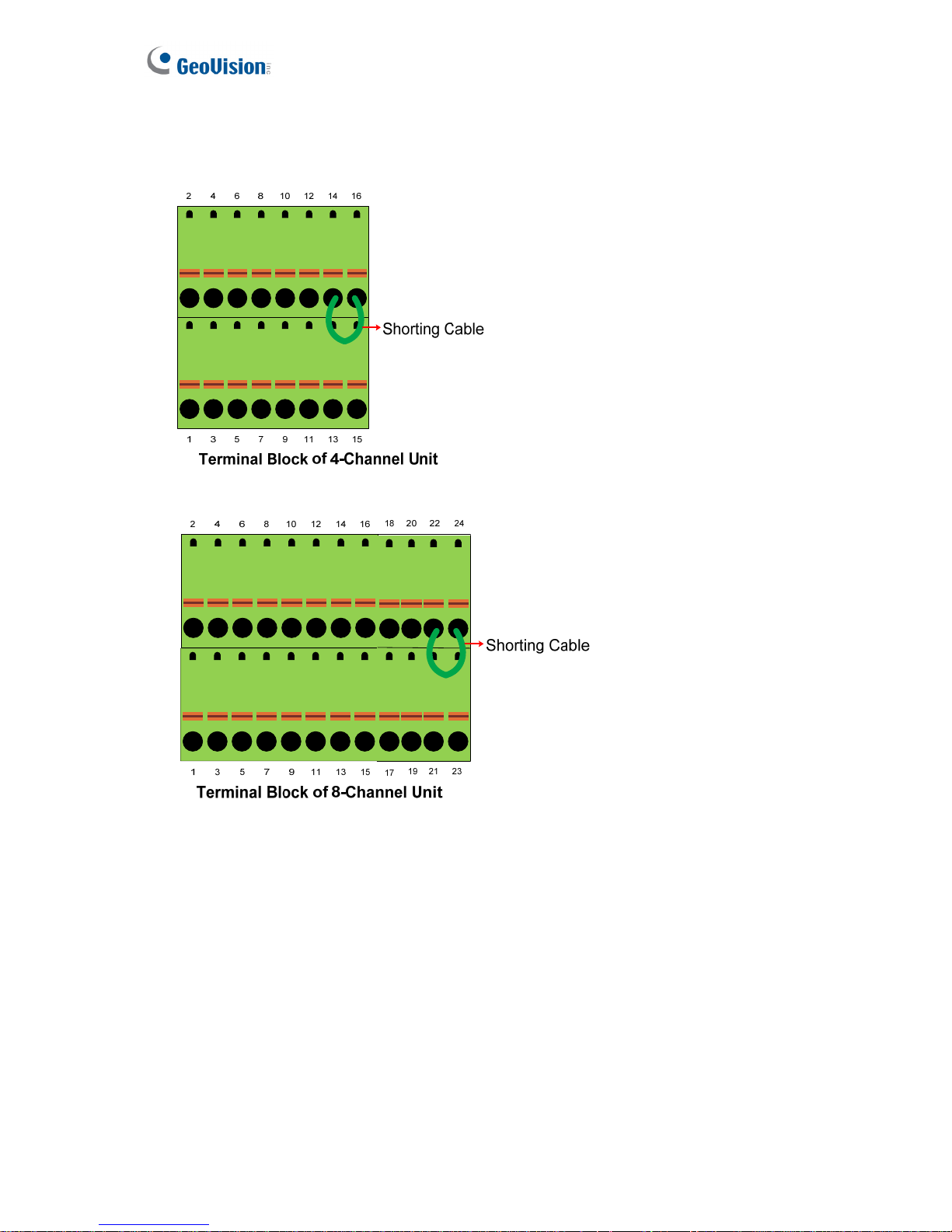
1. Connect the Shorting Cable to Pins 14 and 16 (4-chaneel unit) or Pins 22 and 24
(8-channel unit) on the terminal block.
Figure 3-5
2. Power on the unit by using a power adaptor. The unit automatically starts after powering
up for 5 seconds.
3. Set up the settings of the GV-Compact DVR V3, such as storage, images, recording and
etc through its OSD or Web interface. See 3.6 Formatting Hard Drive and 3.8 Basic
Operation.
4. Remove the power adaptor. The unit turns off immediately after powering off.
Page 42
Getting Started
33
3
3.3.2 Connecting to a vehicle
IMPORTANT:
Below is an example of how to connect the Anti-Vibration ACC model to the vehicle. Since
each vehicle differs in design, refer to the owner’s manual of your vehicle for details and
carefully follow the safety measures. If you are unsure about how to carry out the
instructions, have the installation done by a properly trained technician.
Connecting the ACC Wire
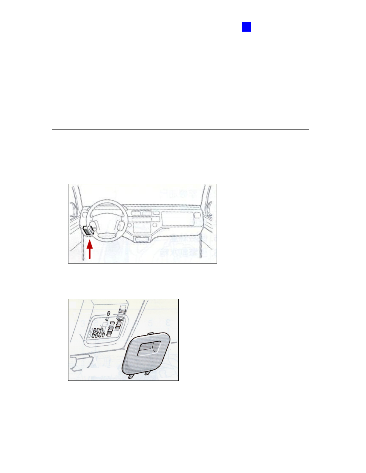
1. Locate the fuse box. The fuse box is usually located below the dashboard and to the left
of the steering wheel. You may need to refer to the owner’s manual of your vehicle.
Figure 3-6
2. Open the cover of the fuse box.
Figure 3-7
Page 43
34
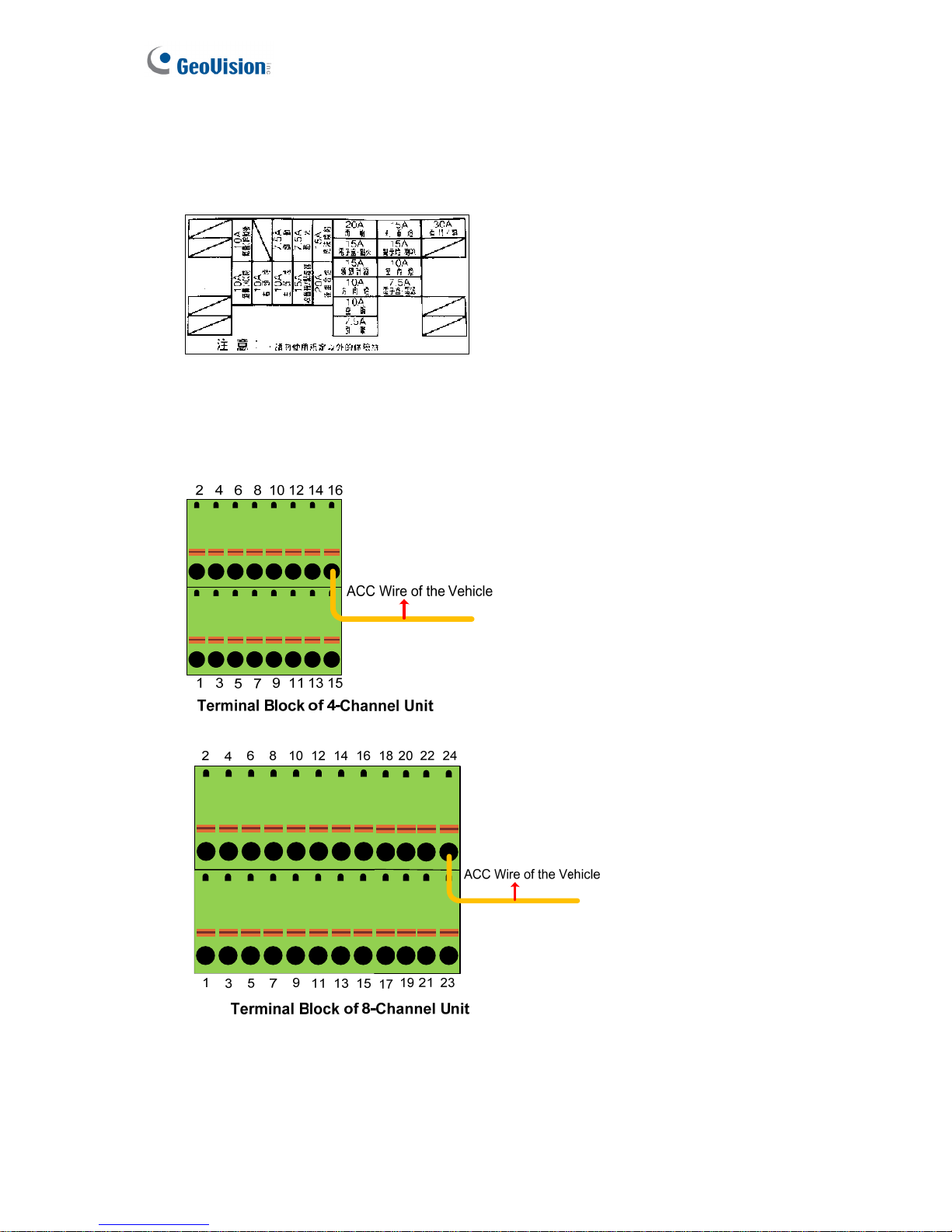
3. Find the fuse specification diagram in the owner’s manual, which tells you what each
fuse controls. Look for the fuse location of the “cigarette lighter.” The fuse diagram is
sometimes located on the back of the fuse box cover.
Figure 3-8
4. Connect the ACC wire from the cigarette lighter fuse to Pin 16 (4-channel unit) or Pin
24 (8-channel unit) on the terminal block.
Figure 3-9
Page 44
Getting Started
35
3
Connecting the Power Wire
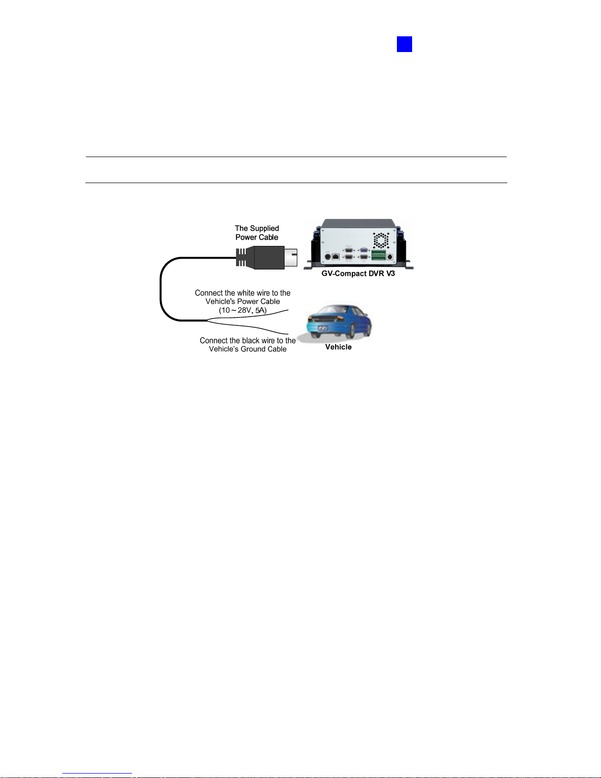
The supplied power cable of the Anti-Vibration ACC model splits into two wires. Connect the
white wire to the vehicle’s power cable and use the black wire to make the ground connection.
Note: The Compact DVR V3 supports the power input of 10V to 28V, 5A.
Figure 3-10
Page 45
36
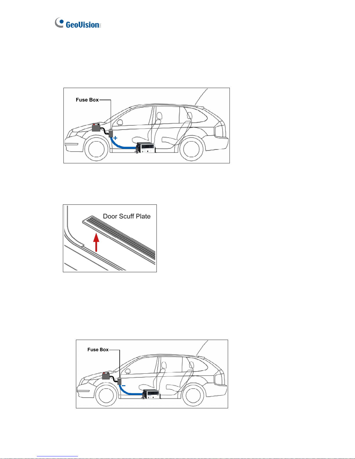
1. Using the fuse specification diagram, locate the power cable connecting to the fuse box.
Connect the white power wire of the GV-Compact DVR V3 to the positive-voltage
power cable. You may need to use a voltmeter to determine which one is the positive
voltage.
Figure 3-11
2. Remove the car door scuff plate and wire the power cable along the driver’s door toward
the back seat.
Figure 3-12
3. Use one of the two methods below to connect the black ground wire of the GV-Compact
DVR V3.
• Method 1: Connect the black ground wire to the negative-voltage power cable from
the fuse box.
Figure 3-13
Page 46
Getting Started
37
3
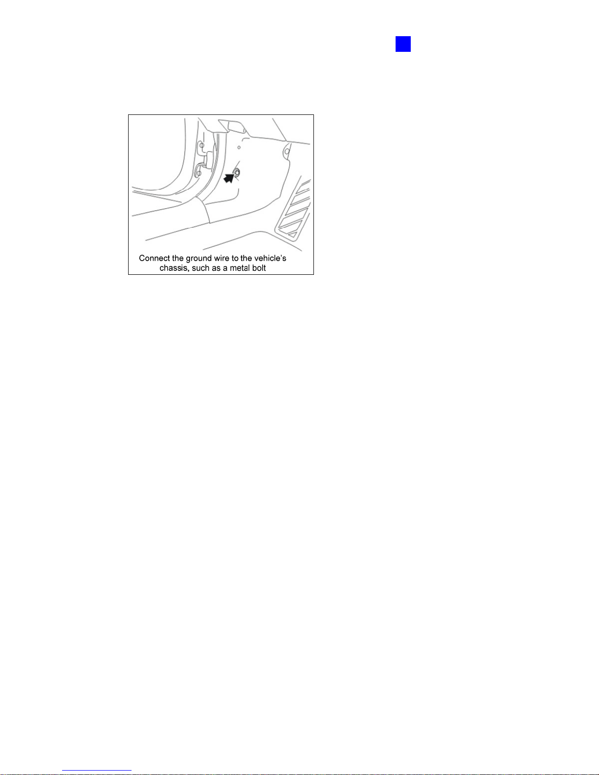
• Method 2: Connect the black ground wire to the vehicle’s chassis so that the wire
contacts the bare metal, for example, a metal bolt nearby.
Figure 3-14
Depending on the make and model of your vehicle, sometimes only one method will work.
When the black ground wire is connected correctly, GV-Compact DVR V3 will
automatically shut down 30 seconds after the car’s power is off. If GV-Compact DVR V3
does not shut down 30 seconds after the car ignition is off, try to connect the black ground
wire using the other method.
4. Turn on the car ignition and the GV-Compact DVR V3 should start automatically within 5
seconds. Turn off the car ignition and the GV-Compact DVR V3 should shut down 30
seconds after the car ignition is off.
Page 47
38
3.4 Connecting Optional Video Output Devices
3.4.1 The Four-Channel Unit
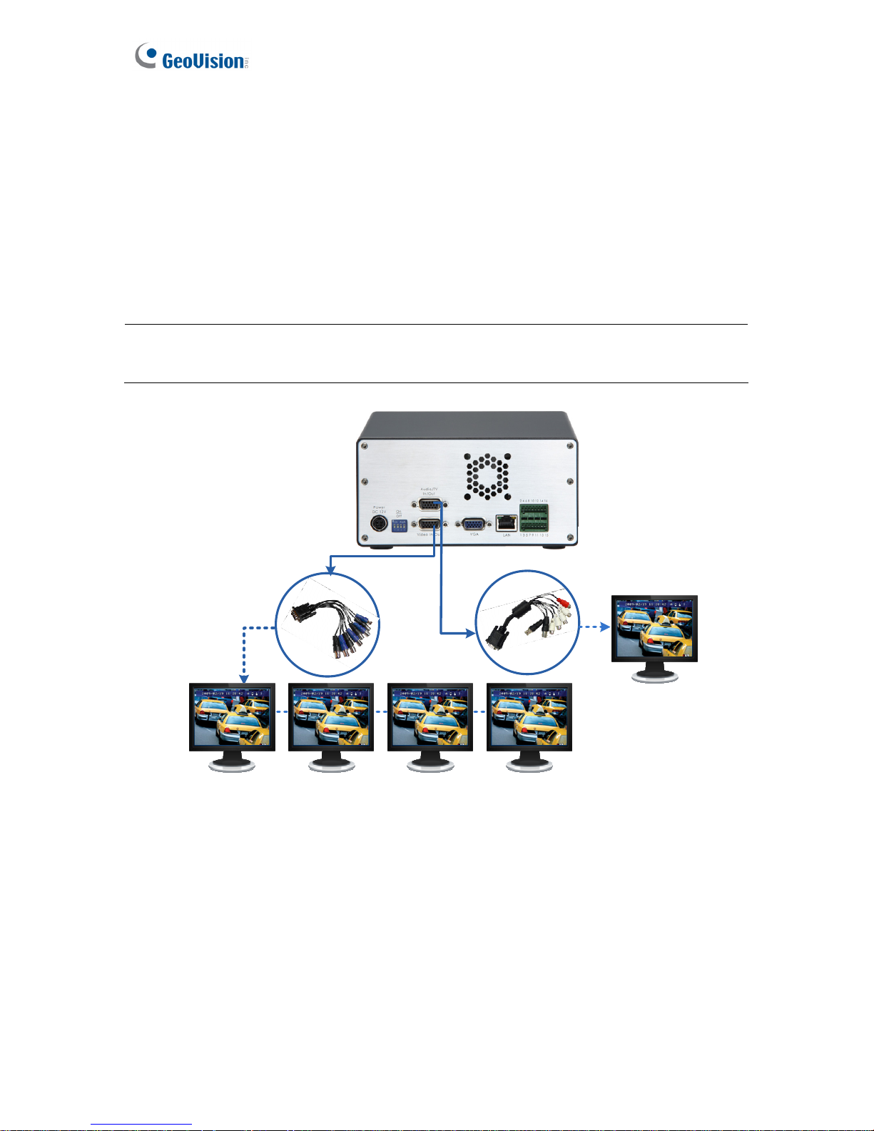
The four-channel GV-Compact DVR V3 offers the looping video output for 4 monitors. It also
offers the spot monitor output to display video sequentially from each video input.
For the settings of the spot monitor, see 4.8.5 Spot Monitor Settings.
Note: To loop out videos, turn the 75 Ω switches to OFF positions. See No. 2, Figure 2-10 /
2-11. The switch number is corresponding to the channel number.
Looping Video Monitors
4 x Black Connector
Spot Monitor
1 x Black Connector
(MUX)
Figure 3-15
Page 48
Getting Started
39
3
3.4.2 The Eight-Channel Unit
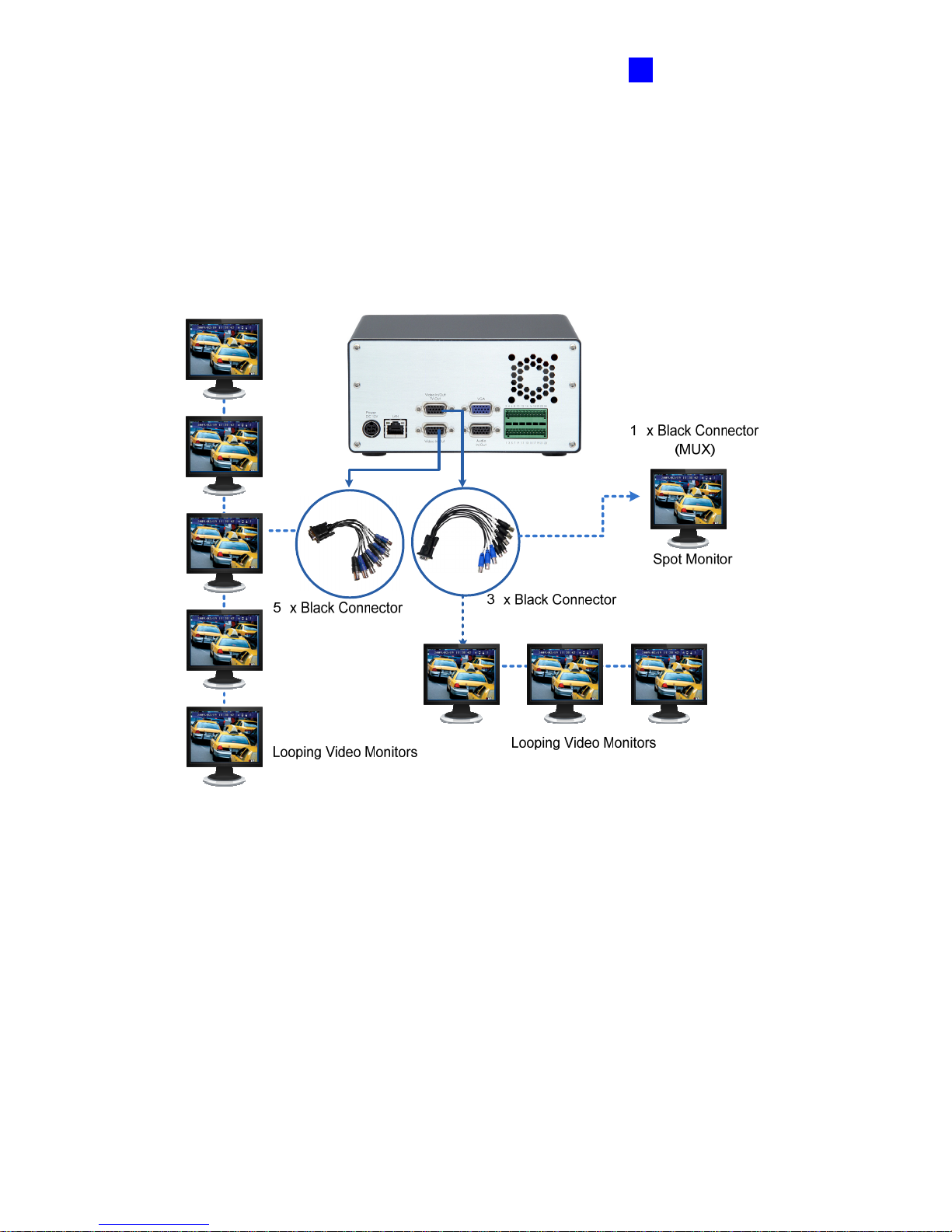
The eight-channel GV-Compact DVR V3 offers the looping video output for 8 monitors. It also
offers the spot monitor output to display video sequentially from each video input.
For the settings of the spot monitor, see 4.8.5 Spot Monitor Settings.
Figure 3-16
Page 49
40
3.5 Installing a Hard Drive
The GV-Compact DVR V3 comes equipped with one or two 3.5” SATA hard drive bay(s) for
video recording. Follow these steps to install the hard drive.
IMPORTANT:
1. The GV-Compact DVR V3 does not support hot swap. Ensure to power off the unit before
removing the hard drive. Also ensure to remove the hard drive only after power was shut
off for more than 60 seconds. This would protect and extend the operating life of the hard
drive.
2. For the Anti-vibration ACC models (GV-LX4C3V, GV-LX8CV1 and GV-LX8CV2), it is
necessary to use the hard drive especially for notebook, vehicle or surveillance
applications, and tightly fasten the unit on the vehicle to prevent vibration and shock
hazard.
3.5.1 The Four-Channel Unit
• Standard Models (GV-LX4C3D1 / GV-LX4C3D2 / GV-LX4C3D2W)
1. Make sure the unit is powered off.
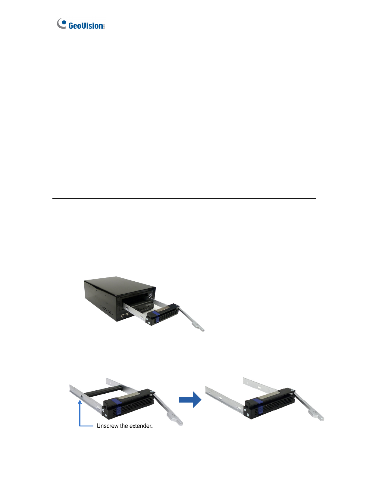
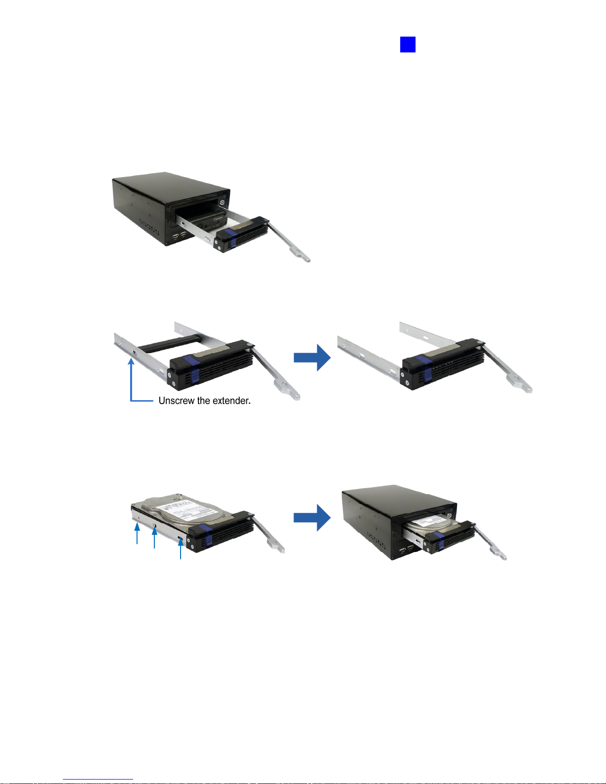
2. Push down the blue button to loose the latch of the hard drive drawer, and pull out the
drawer.
Figure 3-17
3. Unscrew and remove the extender of the drawer.
Figure 3-18
Page 50
Getting Started
41
3
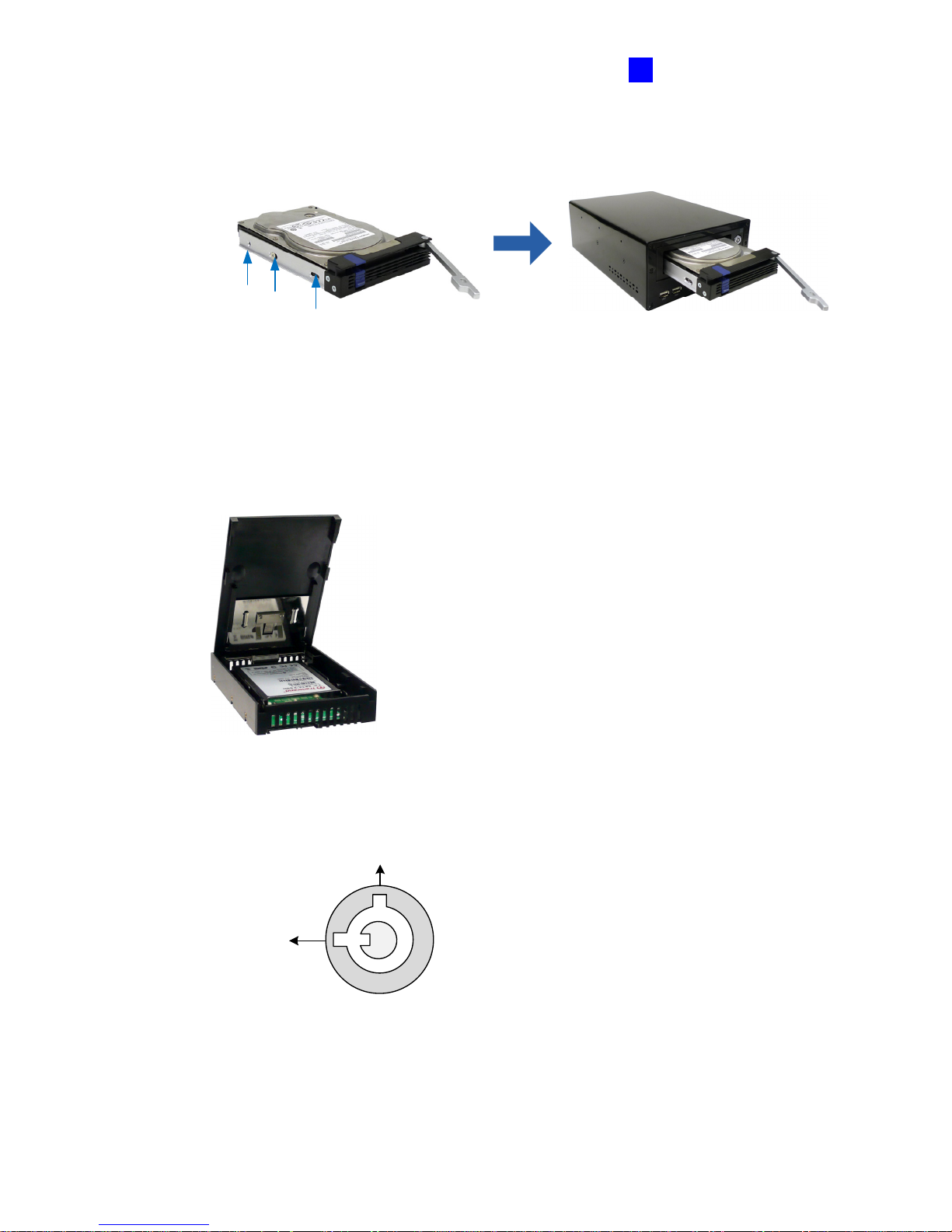
4. Insert the hard drive in the drawer, secure the hard drive with 6 supplied T-Cap
screws, and push the drawer back in the drive bay of the unit.
Screw the hard drive in the drawer.
Push the drawer back.
Figure 3-19
5. To install a 2.5” SATA hard drive, you need a HDD Converter from GeoVision to
enclose the 2.5” hard drive. Insert the Converter installed with a 2.5” hard drive into
the pull-out drive drawer, secure the Converter with 6 supplied T-Cap screws, and
push the drive drawer back in the drive bay.
Figure 3-20
6. Lock the drive bay with the supplied key.
Locked
Unlocked
Figure 3-21
Page 51
42
• Anti-Vibration ACC Model (GV-LX4C3V)
1. Make sure the unit is powered off.
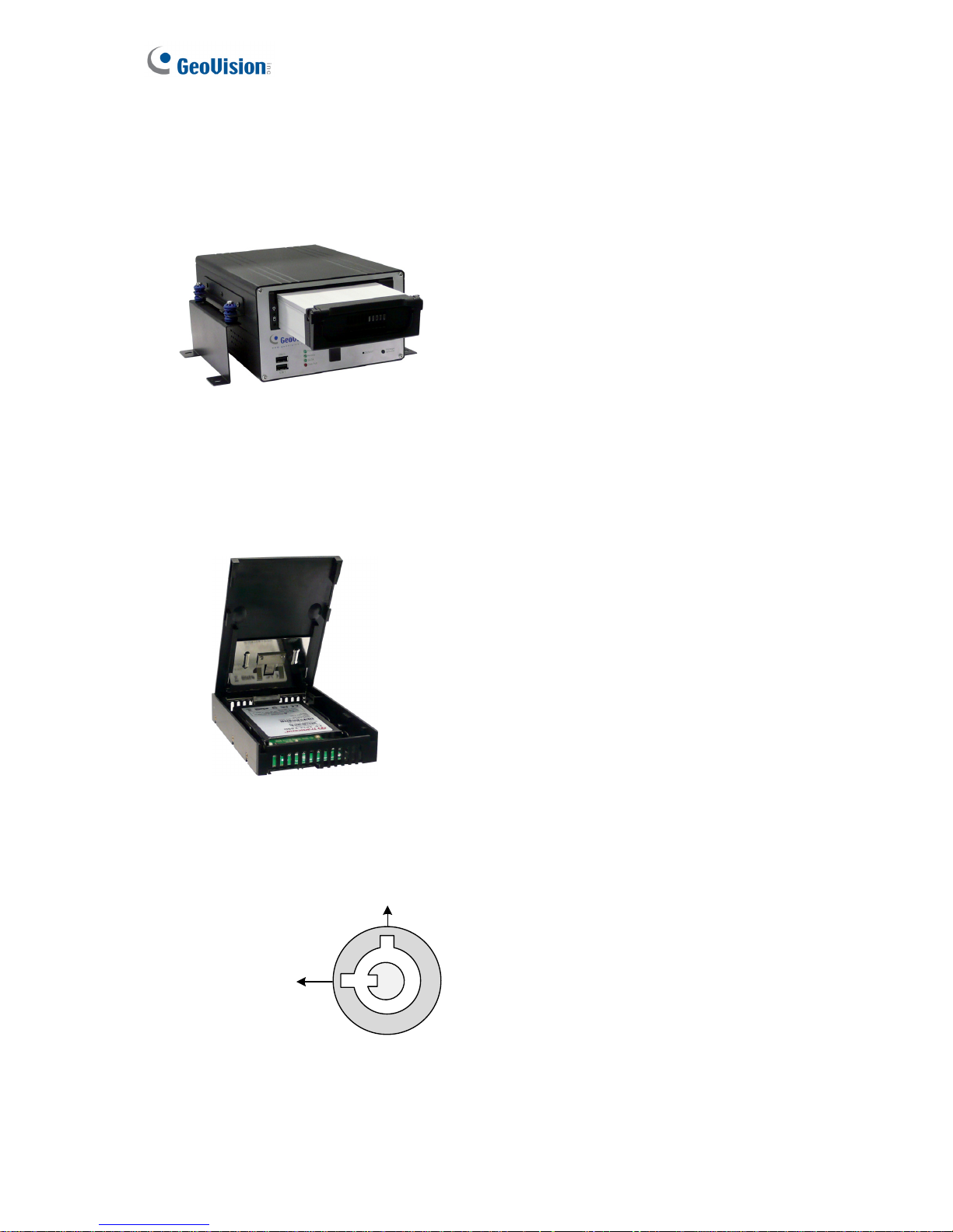
2. Pull out the drive drawer, insert the hard drive in the drawer, secure the hard drive with 4
supplied T-Cap screws, and push the drawer back in the drive bay of the unit.
Figure 3-22
3. To install a 2.5” SATA hard drive, you need a HDD Converter from GeoVision to
enclose the 2.5” hard drive. Insert the Converter installed with a 2.5” hard drive into the
pull-out drive drawer, secure the Converter with 4 supplied screws, and push the drive
drawer back in the drive bay.
Figure 3-23
4. Lock the drive bay with the supplied key.
Locked
Unlocked
Figure 3-24
Page 52
Getting Started
43
3
3.5.2 The Eight-Channel Unit
1. Make sure the unit is powered off.
2. Push down the blue button to loose the latch of the hard drive drawer, and pull out the
drawer.
Figure 3-25
3. Unscrew and remove the extender of the drawer.
Figure 3-26
4. Insert the hard drive in the drawer, secure the hard drive with 6 supplied T-Cap screws,
and push the drawer back in the drive bay of the unit.
Screw the hard drive in the drawer.
Push the drawer back.
Figure 3-27
Page 53
44
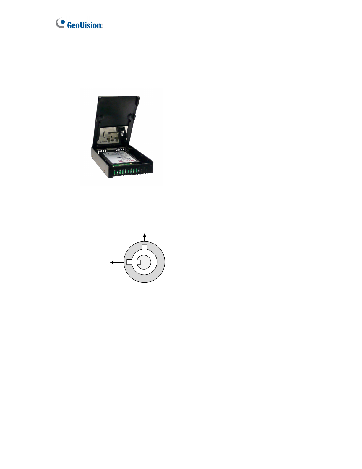
5. To install a 2.5” SATA hard drive, you need a HDD Converter from GeoVision to enclose
the 2.5” hard drive. Insert the Converter installed with a 2.5” hard drive into the pull-out
drive drawer, secure the Converter with 6 supplied T-Cap screws, and push the drive
drawer back in the drive bay.
Figure 3-28
6. Lock the drive bay with the supplied key.
Locked
Unlocked
Figure 3-29
Page 54

Getting Started
45
3
3.6 Turning On / Off the Power
3.6.1 Turning On the Power
1. Connect the GV-Compact DVR V3 to the power, and the Power LED should turn on. If a
HDD is installed on the GV-Compact DVR V3, the HDD Power LED should turn on as
well.
2. The system starts initializing for several seconds. After this, the Ready LED will turn to
green and the main screen will be displayed.
If the GV-Compact DVR V3 is connected to the ACC wire of the vehicle, the unit will
automatically start after you power on the vehicle for 5 seconds. Power is supplied to the unit
as long as the vehicle ignition is on.
3.6.2 Turning Off the Power
Before unplugging the power cable, ensure both the HDD LED and HDD Activity LED turn off;
otherwise, the recorded video may be lost.
If the GV-Compact DVR V3 is installed in a vehicle, the unit will automatically turn off after you
power off the vehicle for 30 seconds. During the 30 seconds, the GV-Compact DVR V3 will
stop recording and the hard drive will be removed from the system automatically.
Page 55
46
3.7 Formatting a Hard Drive
The GV-Compact DVR V3 is a Linux-based system. You must follow the steps below to format
the hard drive before recording.
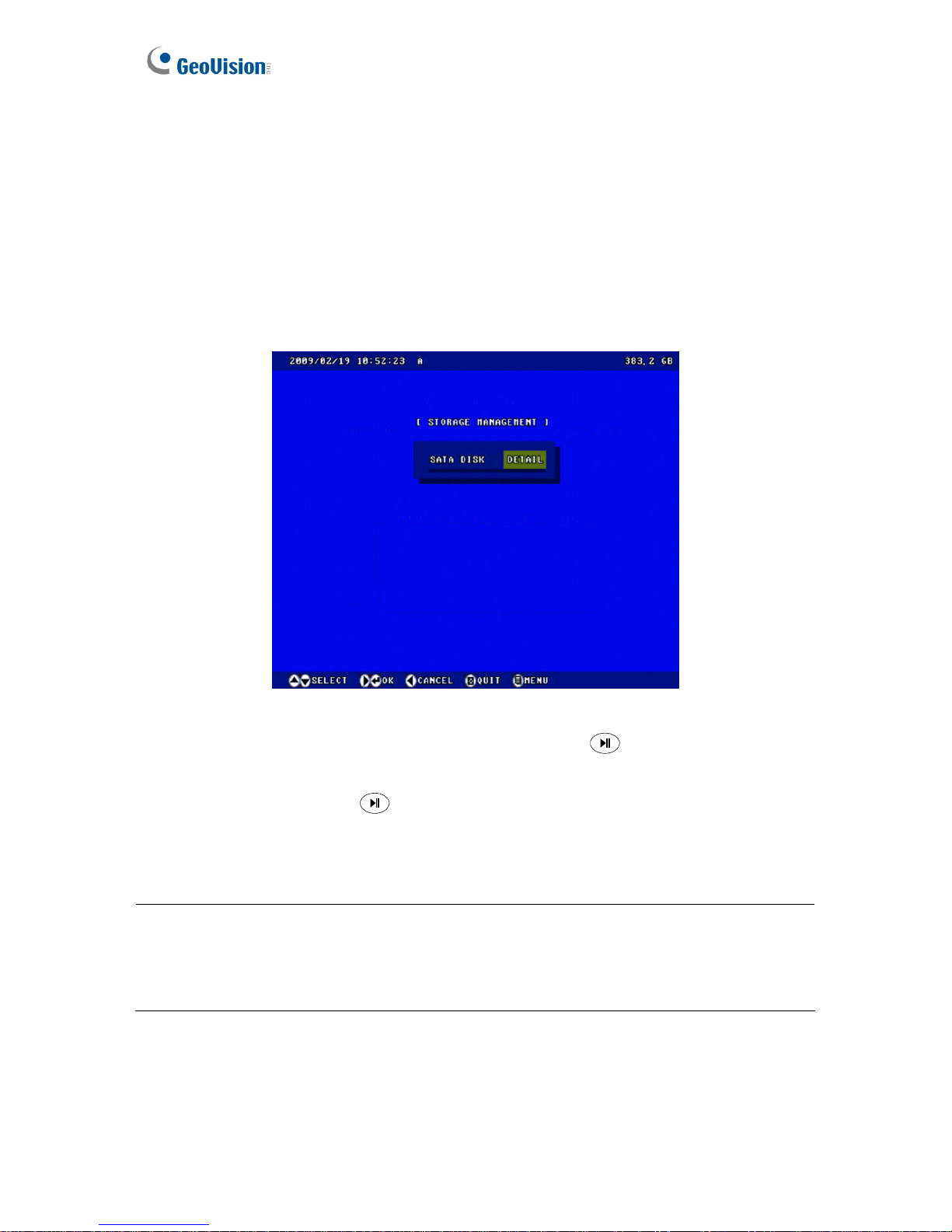
1. Press the Menu button on the Remote Control to enter the main menu.
2. Select ADVANCED, select STORAGE SETTINGS, and then select STORAGE
MANAGEMENT. The model name of the connected hard drive appears.
Figure 3-30
3. Move the focus to DETAIL, select FORMAT and press the
button. You will be
prompted to confirm the action.
4. Select YES and press the
button to start formatting. The format progress will appear
in the top right of the screen, e.g. “PART 1: 94/100”. When the format is complete, the
amount of free disk space will be displayed.
Note:
1. The maximum space of one partition is 200 GB.
2. The connected USB mass storage device must also be formatted according to above
instructions before use.
Page 56
Getting Started
47
3
3.8 Main Screen Overview
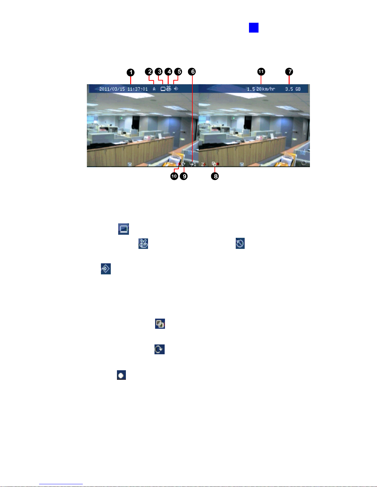
Figure 3-31
1. Date and time: Indicates the current date and time when viewing live video.
2. A / B / C: Indicates the type of device defined for the GV-Compact DVR V3.
3. Monitoring icon
: Appears when the monitoring is activated.
4. Manual recording icon
or Schedule recording icon : Appears when the
recording is started manually or by schedule.
5. Input icon
: Appears when the input device is installed and activated.
6. Channel number/Camera name: Displays the camera number or name.
7. Hard disk status: Indicates the amount of free space on the hard disk. When the disk is
full, the status will turn to red.
8. Motion detection mode icon
: Appears when the camera is set to the recording
mode of motion detection.
9. Round-the-clock mode icon
: Appears when the camera is set to the recording
mode of round-the-clock.
10. Recording icon
: Appears when the monitoring is started. A red icon indicates the
image of the camera is being recorded.
11. Vehicle speed: Indicates the average speed of the vehicle when the GPS function is
enabled. This function is only available for the Anti-Vibration ACC models (GV-LX4C3V,
GV-LX8CV1 and GV-LX8CV2).
Page 57
48
3.9 Basic Operation
This section describes the basic operation of the GV-Compact DVR V3.
3.9.1 Date/Time Adjustment
It is recommended that you enter the current date and time before start recording so that the
correct date and time is associated with all videos.
• To adjust the date and time, press the Menu button on the Remote Control, select
ADVANCED and then select DATE AND TIME. For details, see 4.8.1 Date and Time.
3.9.2 Recording Operation
Before start recording, configure the recording settings properly according to your needs.
• To start recording, press the REC button on the Remote Control to record video onto the
hard drive with the corresponding programmed recording settings. The RED recording
icon
will appear on the corresponding camera screen. The HDD Power LED and
HDD Activity LED lights will be blinking, indicating the GV-Compact DVR V3 is in
recording mode.
• To stop recording, press the Stop button on the Remote Control at any time.
To Steps
Set the recording mode
Press the Menu button and select MONITORING
SETTINGS.
Activate the audio recording
1. Press the Menu button, select CHANNEL SETTINGS,
press one Channel button (Ch1 - CH4 for the
four-channel unit; CH1 - CH8 for the eight-channel unit),
and select VIDEO/AUDIO SETTINGS.
2. Select AUDIO RECORDING, change OFF to ON.
Set the recording schedule
1. Press the Menu button, select RECORDING
SCHEDULE, and select one of scheduling methods. See
4.5 Recording Schedule.
2. To start scheduled recording, press the Menu button,
select MONITORING SETTINGS, change MONITORING
MODE to SCHEDULE, and then select START.
Set the pre-recording and
post-recording
Press the Menu button, select CHANNEL SETTINGS, press
one Channel button (Ch1 - CH4 for the four-channel unit;
CH1 - CH8 for the eight-channel unit), and select ALARM
SETTINGS.
Page 58

Getting Started
49
3
3.9.3 Search/Playback Operation
To access the recorded video for playback, press the Search button to have several search
and playback options. For details, see 4.6 Search / Playback.
3.9.4 PTZ Operation
To install the PTZ camera, press the Menu button on the Remote Control, select CHANNEL
SETTINGS, press one Channel button (Ch1 - CH4 for the four-channel unit; CH1 - CH8 for
the eight-channel unit), and then select PTZ Settings. For details, see 4.1.7 PTZ Settings.
To control the PTZ movement, press the Channel button to display the PTZ channel, and use
directional buttons to control the PTZ.
3.9.5 Channel Number and Camera Name
To display the channel number or camera title, see 4.8.4 Display Settings. To change the
camera name, see 4.1.1 Channel Name.
3.9.6 Video Backup
To back up data and video on a DVD disc or USB storage device, see 4.8.9 Backup.
Page 59
50
Chapter 4 OSD Menu Configurations
The GV-Compact DVR V3 is configured through a series of menus on screen by using the
Remote Control. This section describes the functions and options in the on-screen display
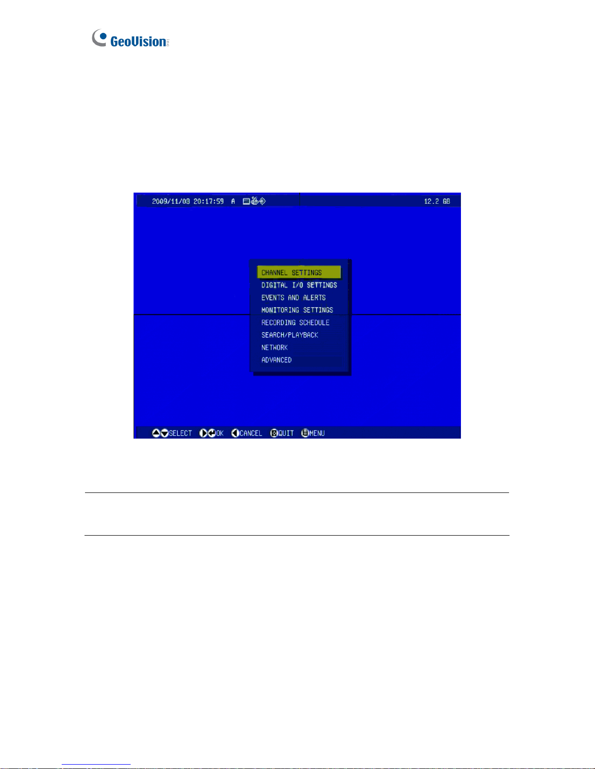
(OSD) menus. To enter the main menu, press the Menu button on the Remote Control. Eight
submenus will appear as shown below.
Figure 4-1
Note: A few of functions are only available in Web-based configurations. For the functions of
IP filtering, Visual Automation and Backup Center, see Chapter 6 Remote Configurations.
Page 60
OSD Menu Configurations
51
4
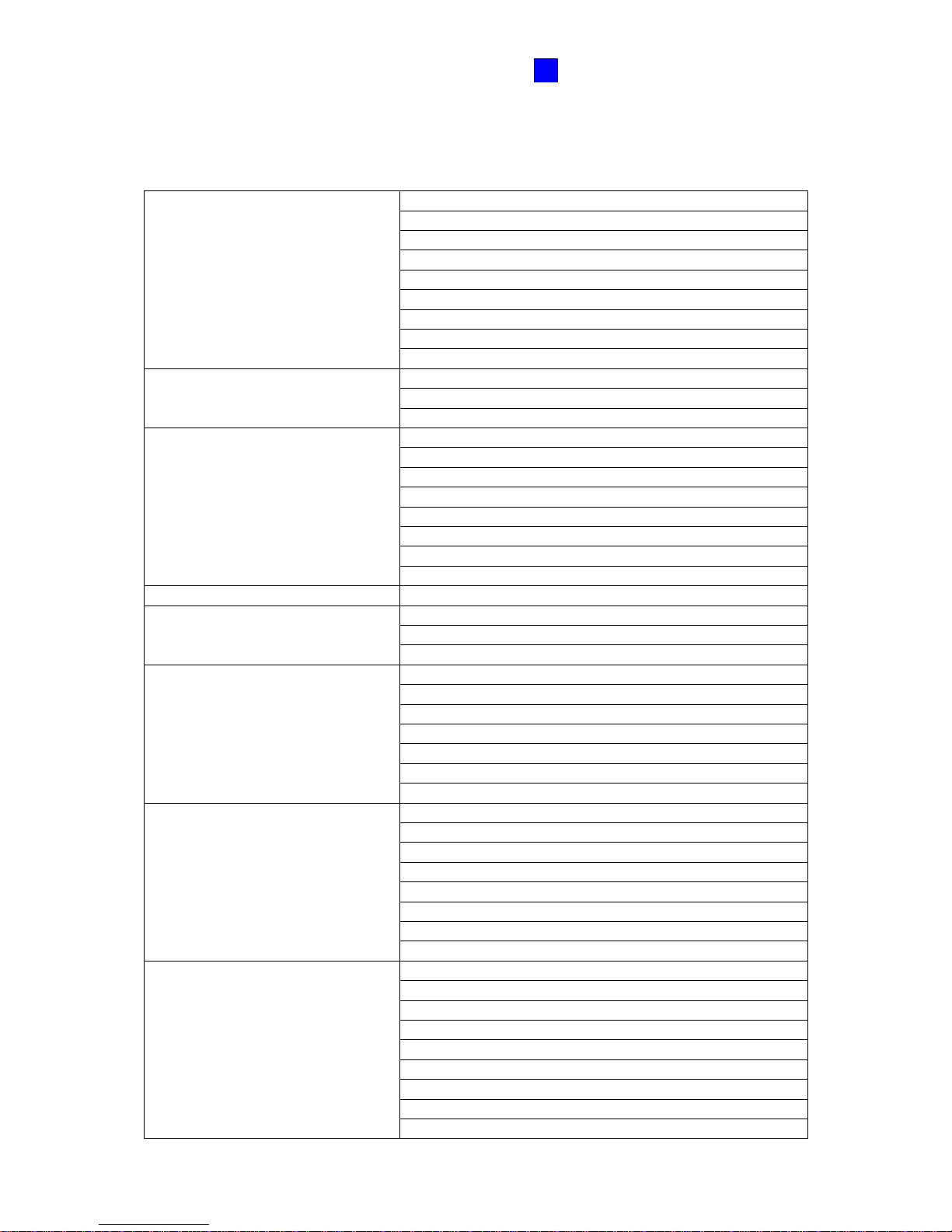
List of Main Menu Options
Find the topic of interest by referring to the section number prefixed to each option.
4.1.1 CHANNEL NAME
4.1.2 VIDEO/AUDIO SETTINGS
4.1.3 MOTION DETECTION
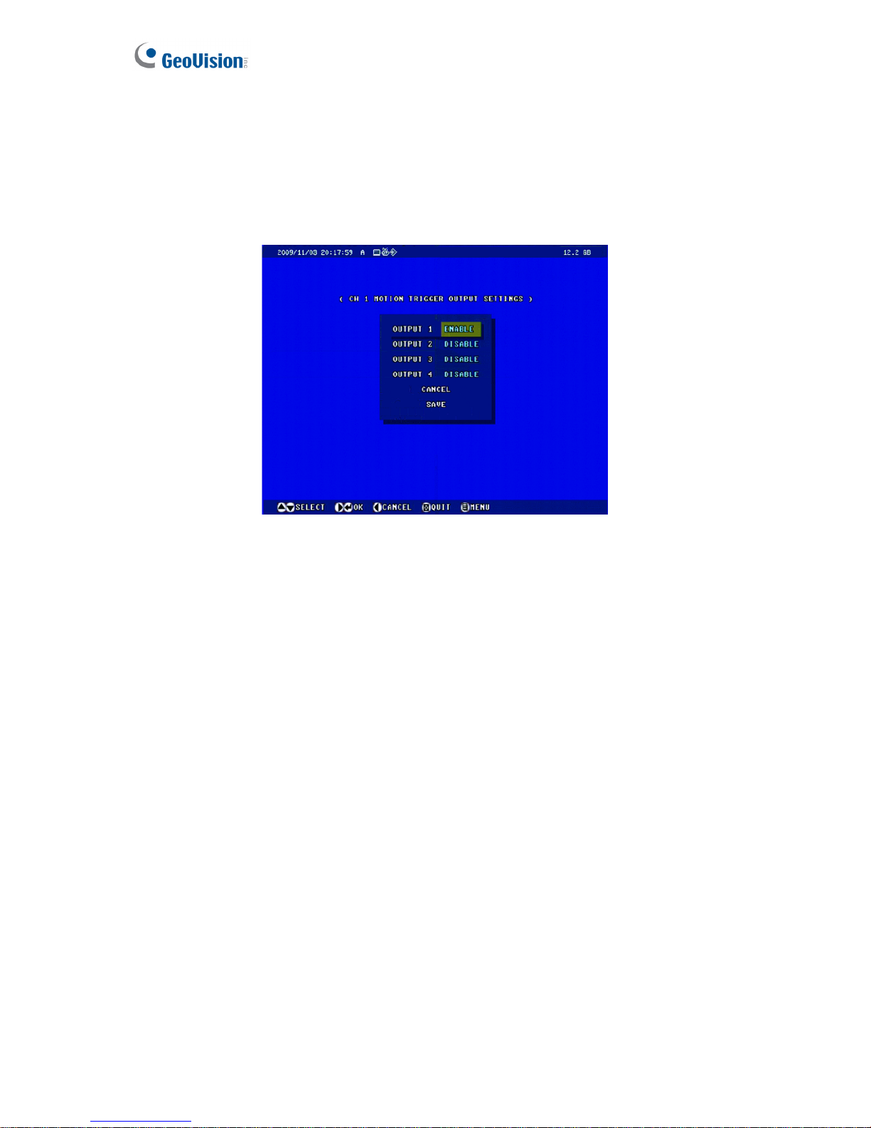
4.1.4 MOTION TRIGGER OUTPUT SETTINGS
4.1.5 ALARM SETTINGS
4.1.6 CAMERA SETTINGS
4.1.7 PTZ SETTINGS
4.1.8 PTZ CONTROL
4.1 CHANNEL SETTINGS
4.1.9 PRIVACY MASK
4.2.1 DIGITAL INPUT SETTINGS
4.2.2 DIGITAL OUTPUT SETTINGS
4.2 DIGITAL I/O SETTINGS
4.2.3 GPS SETTINGS
4.3.1 E-MAIL
4.3.2 FTP
4.3.3 CENTER V2
4.3.4 VSM
4.3.5 GV-GIS
4.3.6 VIDEO GATEWAY / RECORDING SERVER
4.3.7 REMOTE PLAYBACK
4.3 EVENTS AND ALERTS
4.3.8 3GPP
4.4 MONITORING SETTINGS
4.5.1 SPECIFIC DAY
4.5.2 CHANNEL SCHEDULE
4.5 RECORDING SCHEDULE
4.5.3 I/O MONITOR
4.6.1 TIME MAP LIST
4.6.2 LIST ALL
4.6.3 MANUAL RECORDING LIST
4.6.4 ALARM RECORDING LIST
4.6.5 MOTION RECORDING LIST
4.6.6 TIME SEARCH
4.6 SEARCH/PLAYBACK
4.6.7 ADVANCED SEARCH
4.7.1 NETWORK STATUS
4.7.2 CONNECTION SETTINGS
4.7.3 WIRELESS SETTINGS
4.7.4 ADVANCED TCP/IP
4.7.5 UMTS SETTINGS
4.7.6 DDNS SETTINGS
4.7.7 MULTICAST SETTINGS
4.7 NETWORK
4.7.8 WEB USER ACCOUNT INFO
4.8.1 DATE AND TIME
4.8.2 FIRMWARE SETTINGS
4.8.3 STORAGE SETTINGS
4.8.4 DISPLAY SETTINGS
4.8.5 SPOT MONITOR SETTINGS
4.8.6 ALERT SETTINGS
4.8.7 SYSTEM SETTINGS
4.8.8 SYSTEM LOG
4.8 ADVANCED
4.8.9 BACKUP
Page 61
52
4.1 Channel Settings
In Channel Settings, you can adjust the device settings for each channel.
To set up a channel, press the Menu button on the Remote Control, select CHANNEL
SETTINGS, press one Channel button (CH1 – CH4 for the four-channel unit; CH1 – CH8 for
the eight-channel unit), and select one of the setting options. These setting options are
described in the following.
4.1.1 Channel Name
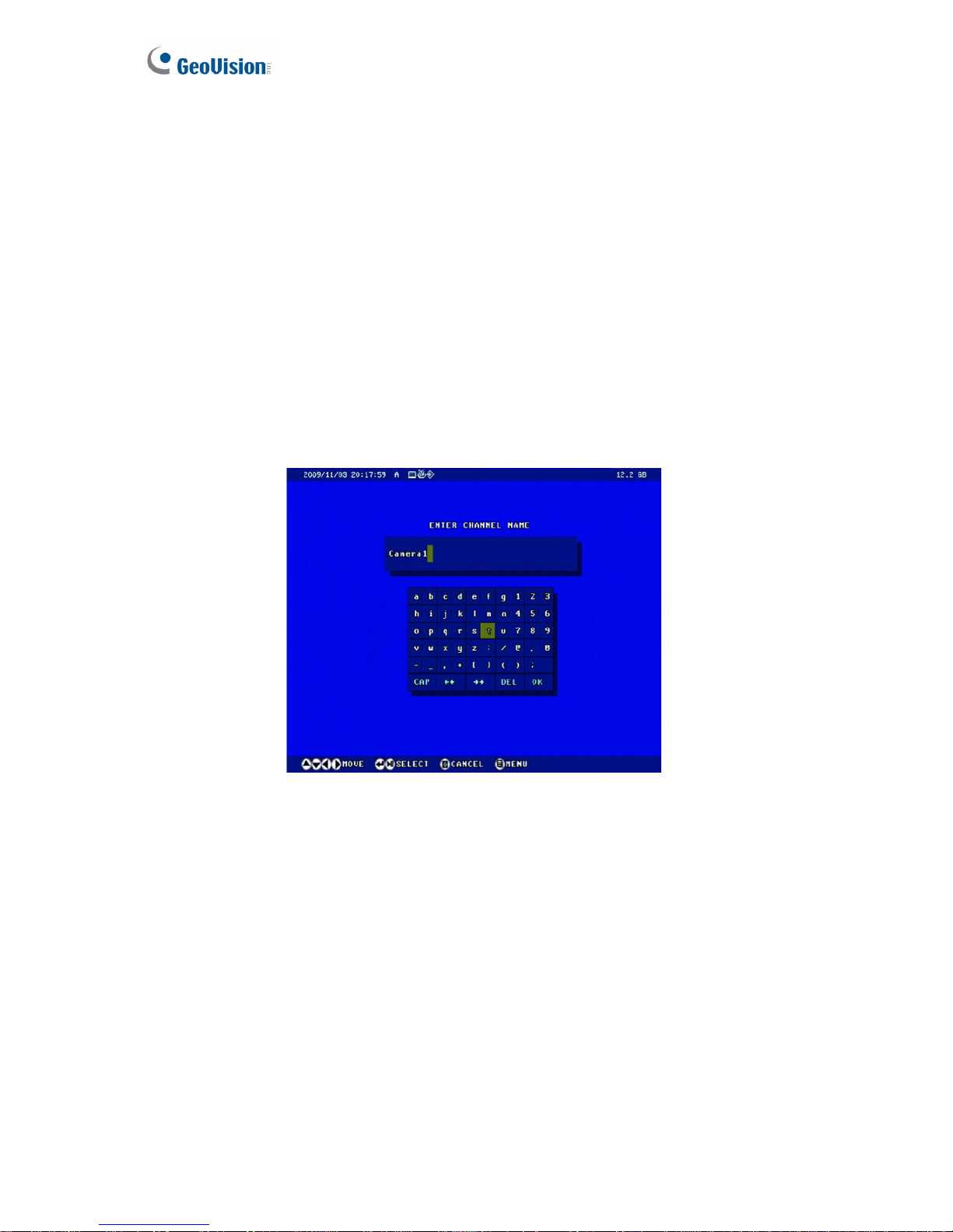
Enter a descriptive name for the channel by using the on-screen keypad. Select OK from the
on-screen keypad to save your settings.
Figure 4-2
Page 62
OSD Menu Configurations
53
4
4.1.2 Video/Audio Settings
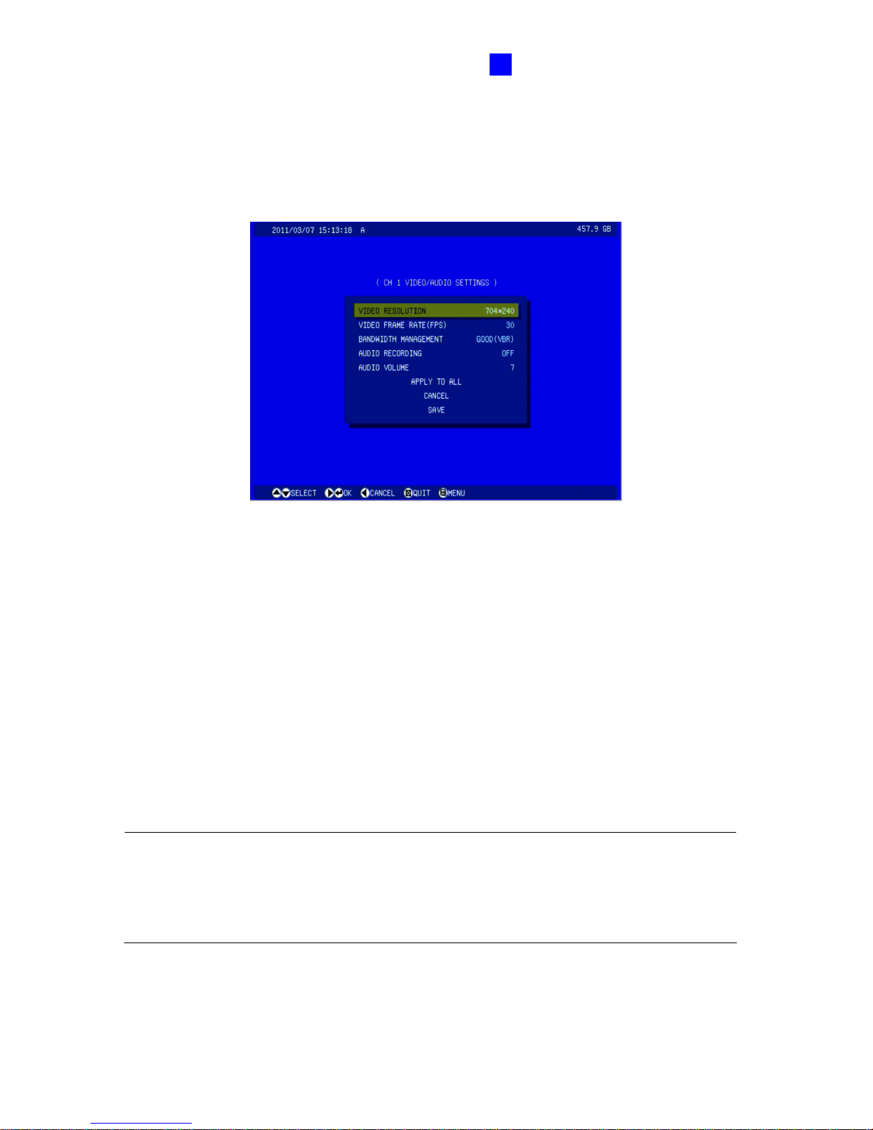
You can adjust the audio and video settings for the selected channel. Select APPLY TO ALL
to apply the same settings to all four channels or all eight channels, depending on the unit you
use.
Figure 4-3
VIDEO RESOLUTION: Select the video resolution from 704 x 480, 704 x 240 and 352 x
240 for NTSC format; or 704 x 576, 704 x 288 and 352 x 288 for PAL format.
VIDEO FRAME RATE: Select the frame rate from 2, 3, 5, 7.5, 10, 15 and 30 fps.
Bandwidth Management: Select the recording quality at different levels from POOR
(VBR), FAIR (VBR), GOOD (VBR), GREAT (VBR), EXCELLENT (VBR), 128 KBPS (CBR),
256 KBPS (CBR), 768 KBPS (CBR), 1024 KBPS (CBR), and 1536 KBPS (CBR).
AUDIO RECORDING: Enable the audio recording.
AUDIO VOLUME: Select the audio volume from 0 to 14. Volume 7 is the default value.
Note: The four-channel GV-Compact DVR V3 models support dual streams, allowing you to
establish up two sets of codec and resolution for a single video transmission. The video
setting on OSD is only for main stream. To enable and configure the dual streams, you need
to use the Web-based interface. For details, see 6.1.1 Video Settings.
Page 63
54
4.1.3 Motion Detection
Motion detection is used to generate an alarm whenever movement occurs in the video image.
You can configure up to 8 areas of different sensitive values for motion detection.
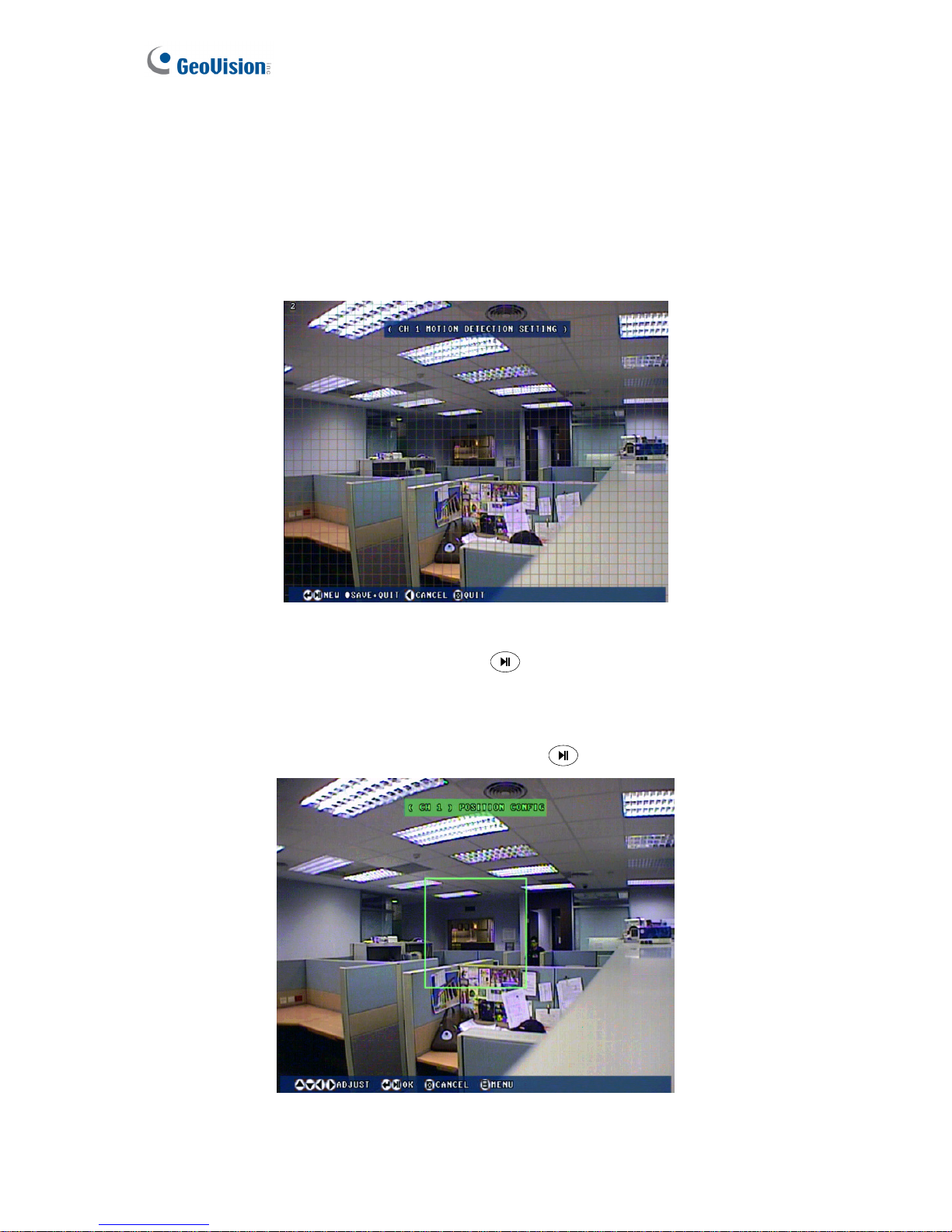
1. Select MOTION DETECTION. This screen appears. The default sensitivity value is 2 for
the whole area.
Figure 4-4
2. To start motion detection settings, press the
button.
3. To clear the default settings, press the Stop button. The message “NO BOXES EXIST”
appears.
4. To define one detection area in the image, press the
button.
Figure 4-5
Page 64
OSD Menu Configurations
55
4
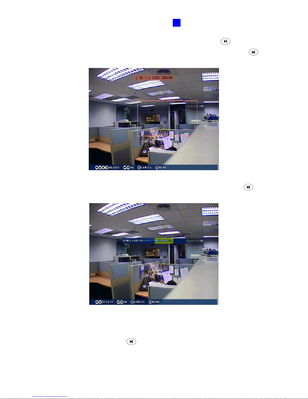
5. Press the directional buttons to place the detection area, and press the
button.
6. Press the directional buttons to modify the size of the detection area, and press the
button.
Figure 4-6
7. Select SENSITIVITY value from Low (1), Medium (2) and High (3), and press the
button. The higher the value, the more sensitive the detection area is to motion.
Figure 4-7
8. Press the REC button to save the settings.
9. To define another detection area with a different sensitivity value, select MOTION
DETECTION again, press the
button, press the Enter button, and repeat Steps 4-8.
Page 65
56
4.1.4 Motion Trigger Output Settings
The alarm output can be triggered simultaneously when motion is detected. The four-channel
unit can connect up to 4 alarm output devices, while the eight-channel unit can connect up to
8 alarm output devices. To activate the output settings, you must also start monitoring
manually or by schedule. See 4.4 Monitoring Settings.
Figure 4-8
Page 66
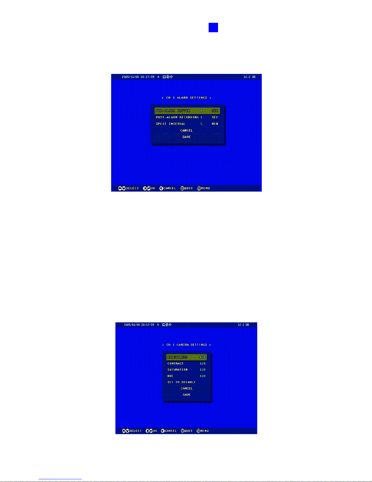
OSD Menu Configurations
57
4
4.1.5 Alarm Settings
You can capture images before and/or after a motion and an I/O event happens.
Figure 4-9
PRE-ALARM BUFFER: Activate video recording before an event occurs. Set the
recording time to 1 or 2 seconds.
POST-ALARM RECORDING: Activate video recording onto the hard disk after an event
occurs. Set the recording time from 1 to 30 seconds.
SPLIT INTERVAL: Set the time length between each event file from 1 to 10 minutes.
4.1.6 Camera Settings
You can modify the video attributes of brightness, contrast, saturation and hue.
Figure 4-10
Page 67
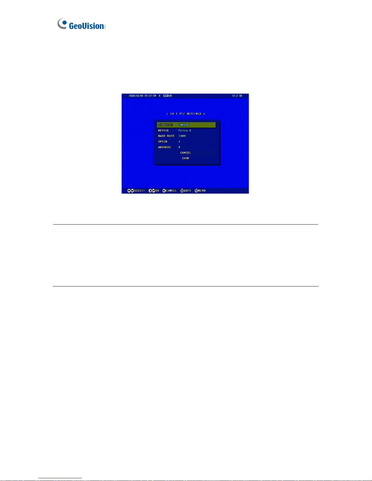
58
4.1.7 PTZ Settings
Through the RS-485 interface on the I/O terminal block, you can connect up to 4 PTZ
cameras with the four-channel unit, and 8 PTZ cameras with the eight-channel unit. To set up
the baud rate, speed and address, consult your PTZ documentation.
Figure 4-11
Note:
1. Currently the GV-Compact DVR V3 does not support the PTZ camera with RS-232
interface.
2. A total of 47 supported PTZ models are listed on the OSD. Using the Web interface, you
have more options for supported PTZ models. For details, see Supported PTZ Cameras,
Appendix F.
Page 68
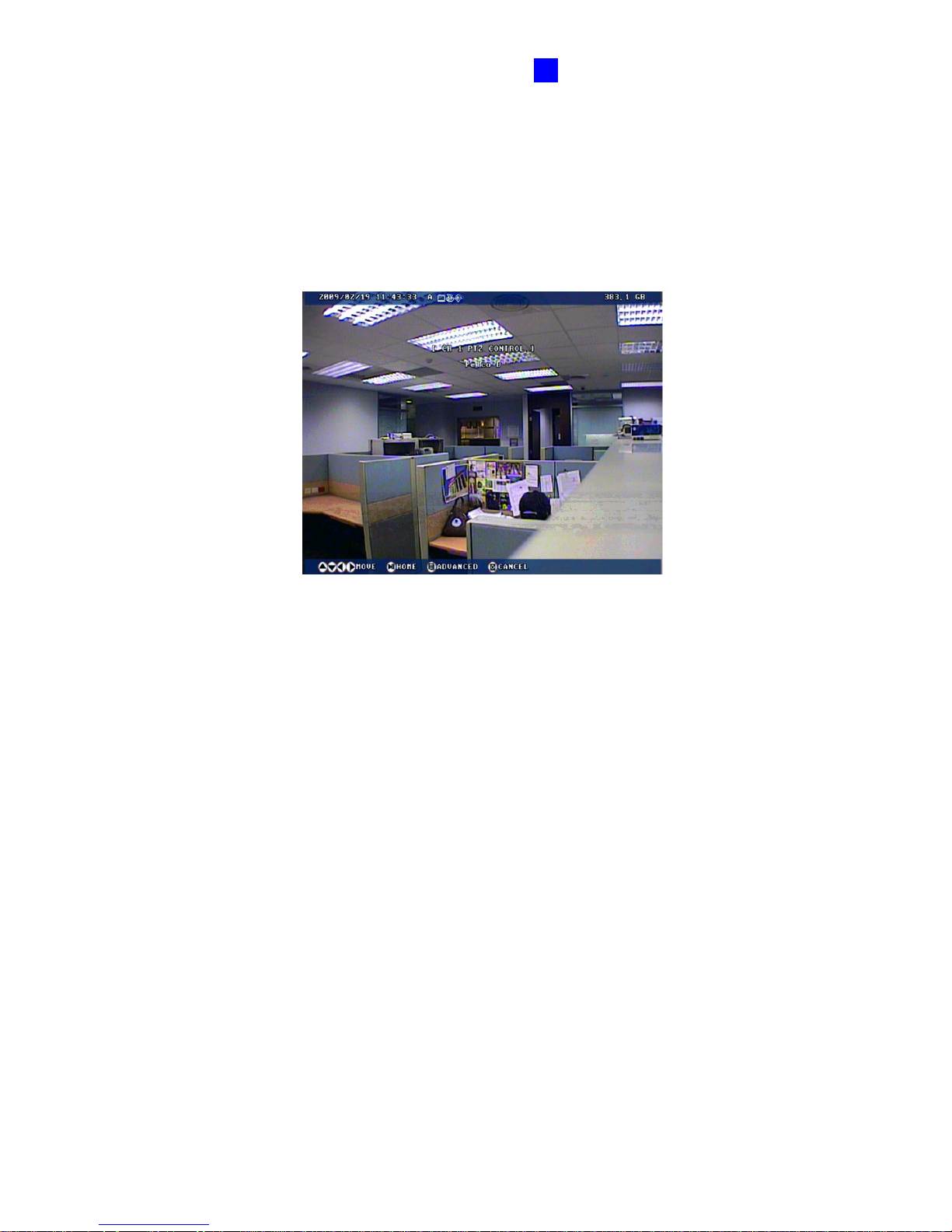
OSD Menu Configurations
59
4
4.1.8 PTZ Control
After setting up the PTZ camera, you can press the Channel button (CH1 - CH4 for the
four-channel unit; CH1 – CH8 for the eight-channel unit) on the remote Control to display the
PTZ channel. Use the directional buttons to control the PTZ movement. Press the Menu
button to access advanced functions. The availability of certain PTZ functions depends on
different models. For details, consult your PTZ documentation.
Figure 4-12
Page 69
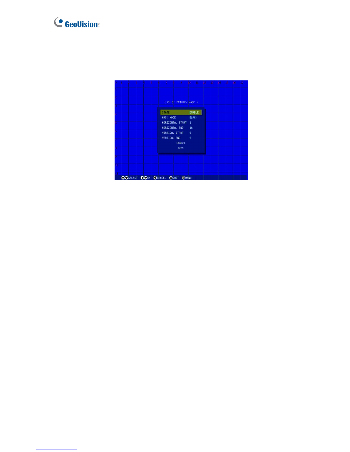
60
4.1.9 Privacy Mask
You can set up the Privacy Mask to block out sensitive areas from view by covering the areas
with black or white boxes in both live view and recorded clips.
Figure 4-13
STATE: Enable the Privacy Mask function.
MASK MODE: Set the mask to be black or white.
HORIZONTAL START: Set the value from 1 to 17 to define where the Privacy Mask starts
horizontally. The value 1 is at the top; the value 17 is at the bottom.
HORIZONTAL END: Set the value from 1 to 17 to define where the Privacy Mask ends
horizontally. The value 1 is at the top; the value 17 is at the bottom.
VERTICAL START: Set the value from 1 to 11 to define where the Privacy Mask starts
vertically. The value 1 is at the left; the value 11 is at the right.
VERTICAL END: Set the value from 1 to 11 to define where the Privacy Mask ends
vertically. The value 1 is at the left; the value 11 is at the right.
Page 70
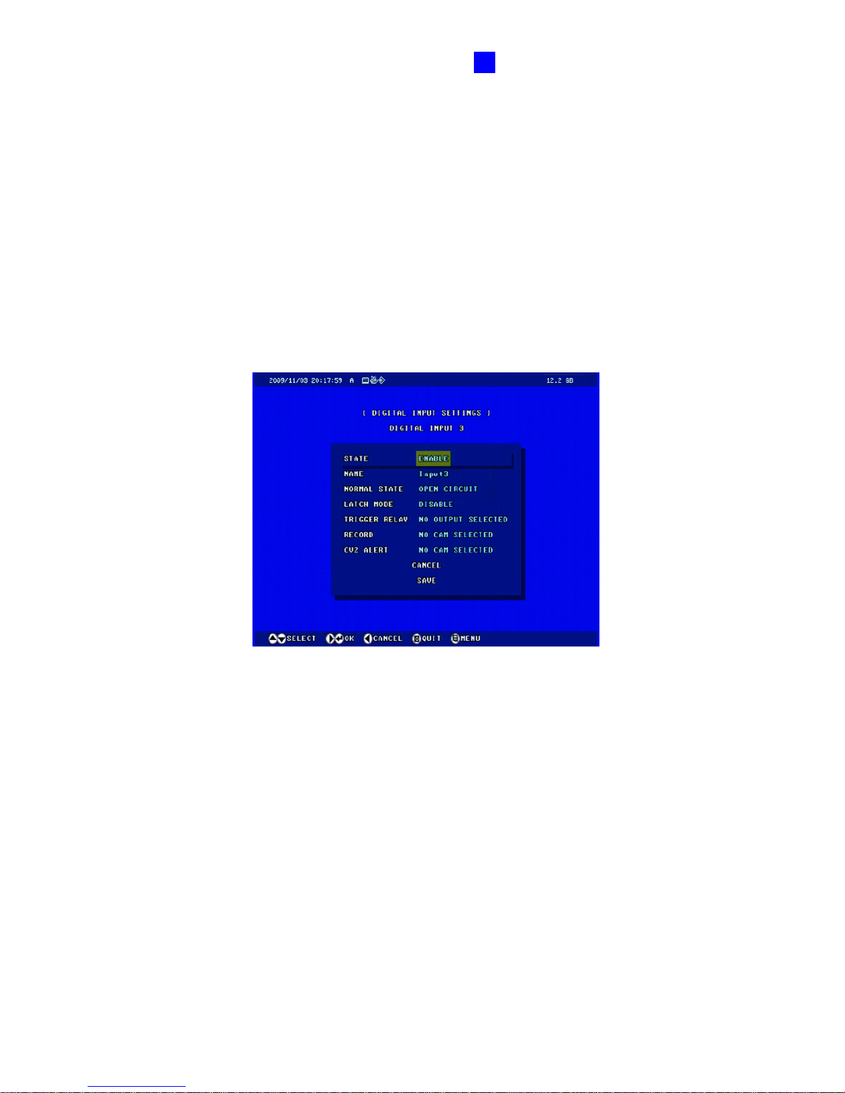
OSD Menu Configurations
61
4
4.2 Digital IO Settings
The I/O terminal block, on the rear panel of the GV-Compact DVR V3, provides the interface
for the applications of digital input, relay output and GPS.
4.2.1 Digital Input Settings
The four-channel unit can connect up to 4 input devices, while the eight-channel unit can
connect up to 8 input devices. To select one input device for setup, press the desired
Channel button (CH1 – CH4 for the four-channel unit; CH1 – CH8 for the eight-channel unit)
on the Remote Control.
Figure 4-14
STATE: Enable the selected input.
NAME: Enter a descriptive name for the input device.
NORMAL STATE: Set the input state to OPEN CIRCUIT (normally open) or GROUNDED
CIRCUIT (normally closed).
LATCH MODE: Enable this mode to have a momentary output alarm.
TRIGGER RELAY: Select the output(s) to be triggered once the input is activated.
RECORD: Select the camera(s) to start recording once the input is activated.
CV2 Alert: Select the camera(s) to send their images to Center V2 when the input is
triggered.
Also see 6.2.1 I/O Control of the Web-based configuration which provides more information
and features of the digital input settings.
Page 71
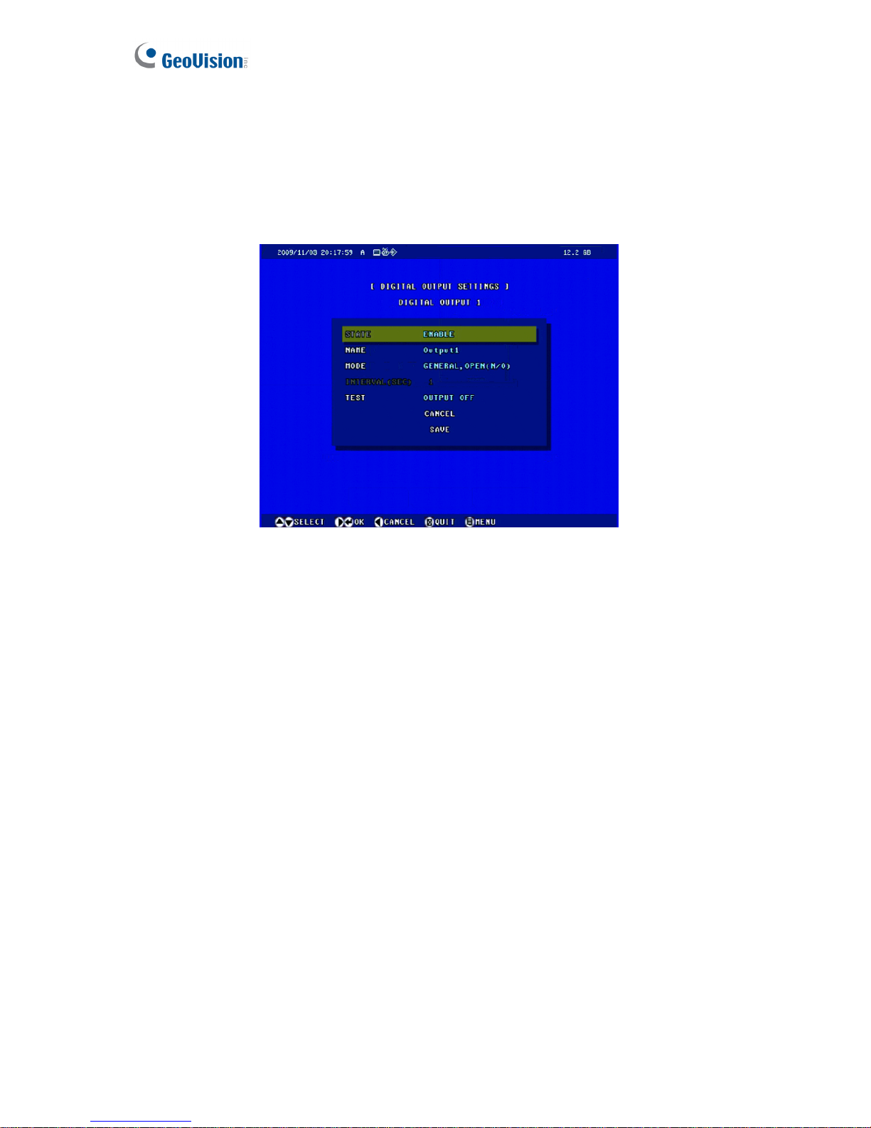
62
4.2.2 Digital Output Settings
The four-channel unit can connect up to 4 output devices, while the eight-channel unit can
connect up to 8 output devices. To select one output device for setup, press the desired
Channel button (CH1 – CH4 for the four-channel unit; CH1 –CH8 for the eight-channel unit)
on the Remote Control.
Figure 4-15
STATE: Enable the selected output.
NAME: Enter a descriptive name for the output device.
MODE: Set the output mode to GENGERAL, OPEN (N/O); GENERAL, GROUNDED
(N/C); TOGGLE, OPEN (N/O); TOGGLE, GROUNDED (N/C); PULSE, OPEN (N/O);
PULSE, GROUNDED (N/C).
INTERVAL: Specify the pulse duration for the pulse mode from 1 to 60 seconds.
TEST: After finishing the above settings, select this option to see if the output device has
response.
Also see 6.2.1 I/O Control of the Web-based configuration which provides more information
and features of the digital output settings.
Page 72
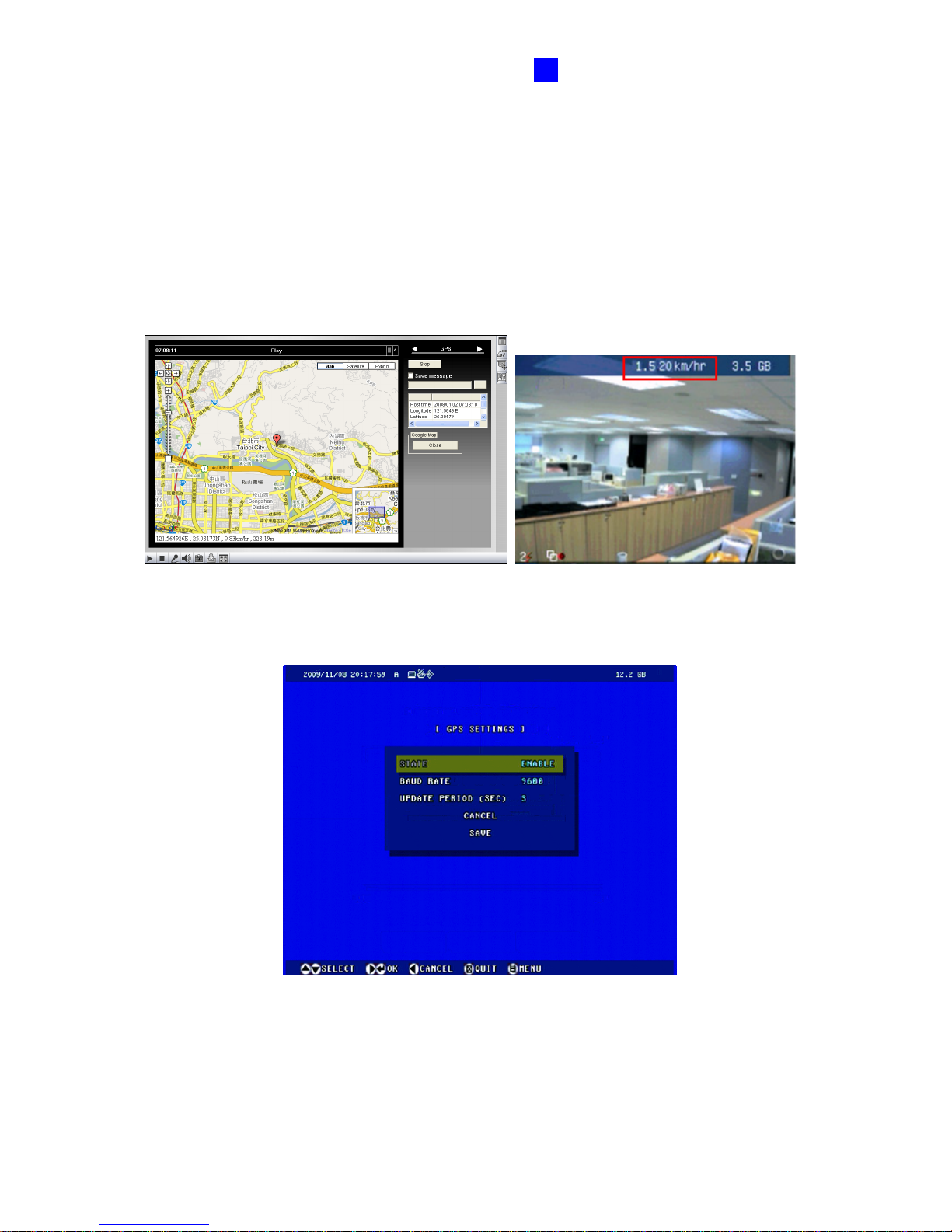
OSD Menu Configurations
63
4
4.2.3 GPS Settings
Note the GPS function is only supported on Anti-Vibration ACC models (GV-LX4C3V /
GV-LX8CV1 / GV-LX8CV2).
The Anti-Vibration ACC models support the Global Position System (GPS) for active vehicle
tracking and location verification. You can track the vehicle location on Google maps and
display the average speed of a vehicle in live view.
Location tracking on Google maps Vehicle speed in live view
Figure 4-16
Figure 4-17
STATE: Enable the GPS function. After the settings, the vehicle speed will show on the
upper-right corner of the main screen.
Page 73
64
BAUD RATE: Two baud rate options are available: 4800 and 9600. By default the value is
9600.
UPDATE PERIOD: Set the update frequency in seconds for GPS data.
To track the location of the GV-Compact DVR V3 on Google Maps, see 8.3 GPS Tracking.
If the monitoring is also activated, the GPS tracks will be recorded along with videos. This
makes it possible to play back video with GPS tracks on maps using the Remote ViewLog
player. See 7.2.5 Playback of GPS Tracks.
Note: The vehicle speed will be recorded with video, but the review of the speed data is not
available on OSD. You can retrieve the video with the speed data using the Remote
ViewLog player. See 7.2.2 Playback over Network.
Page 74

OSD Menu Configurations
65
4
4.3 Events and Alerts
For the events of motion detection or I/O trigger, you can set up these alert methods:
1. Send a captured still image by e-mail or FTP.
2. Notify Center Monitoring Station, Center V2, VSM or GV-GIS, by video or text alerts.
To have above alert methods, you must also set the following features:
• Motion Detection (See 4.1.3 Motion Detection)---optional
• Input Setting (See 4.2.1 Digital Input Settings)
• For e-mail and FTP alerts, it is required to start monitoring (see 4.4 Monitoring
Settings)
Note: The Motion Detection function is an optional setting and it is activated by default.
Page 75
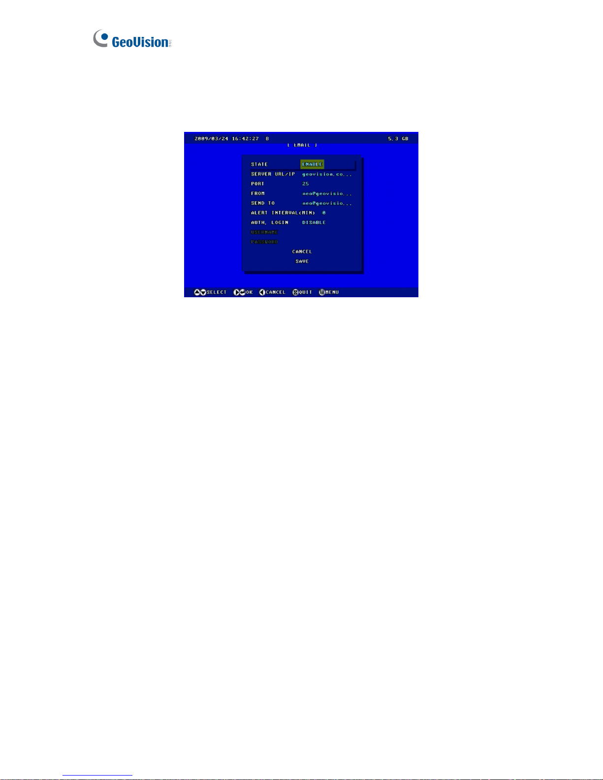
66
4.3.1 E-mail
After a trigger event, the GV-Compact DVR V3 can send the e-mail to a remote user
containing a captured still image.
Figure 4-18
STATE: Enable the e-mail function.
SERVER URL/IP: Enter the URL or IP address of the SMTP server.
PORT: Enter the SMTP server’s port number. Or keep the default value 25.
FROM: Enter the sender’s e-mail address.
SEND TO: Enter the e-mail address(s) you want to send alerts to.
ALERT INTERVAL: Enter the interval between e-mail alerts. The interval can be between
0 and 60 minutes. The option is useful for the frequent event condition. It will ignore any
event triggers during the interval period.
AUTH LOGIN: If the SMTP server needs authentication, enable this option and enter the
valid username and password.
Also see 6.3.1 E-mail of the Web-based configuration which provides more information and
features of the e-mail settings.
Page 76
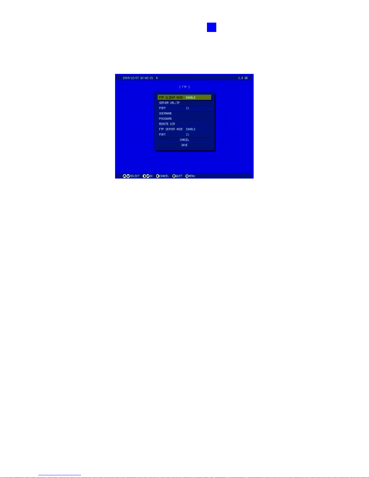
OSD Menu Configurations
67
4
4.3.2 FTP
You can also send the captured still image to a remote FTP server for alerts.
Figure 4-19
FTP CLIENT MODE: Enable the FTP function.
SERVER URL/IP: Enter the host name or IP address of the FTP Server.
PORT: Enter the port number of the FTP Server. Or keep the default value 21.
USERNAME: Enter a valid user name to log into the FTP Server.
PASSWORD: Enter a valid password to log into the FTP Server.
REMOTE DIR: Enter the name of the storage folder on the FTP Server.
FTP SERVER MODE: Enable the GV-Compact DVR V3 to act as a FTP Server, allowing
users to download the AVI files.
PORT: Modify the port of the built-in FTP Server. Or keep the default value 21.
Also see 6.3.2 FTP of the Web-based configuration which provides more information and
features of the FTP settings.
Page 77
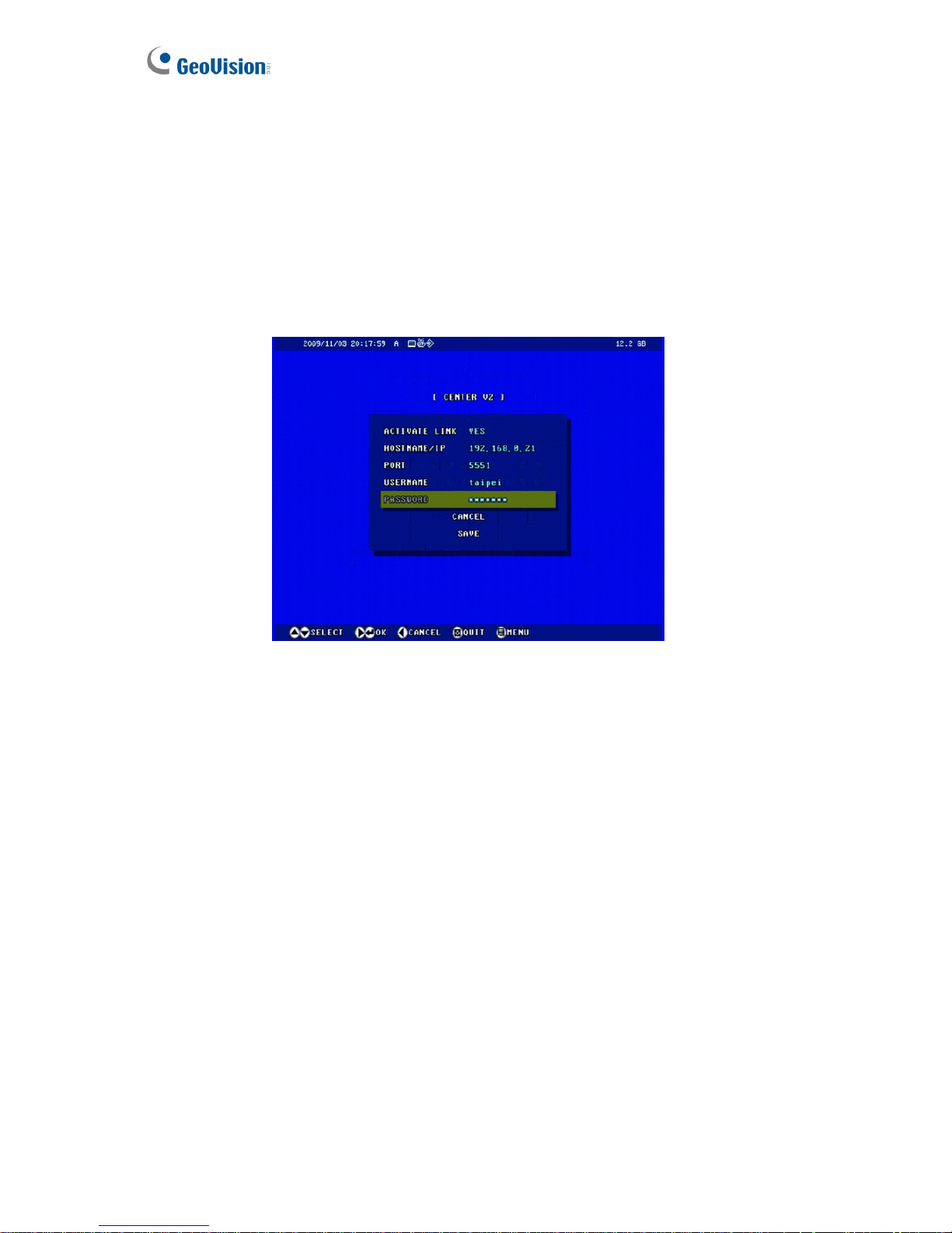
68
4.3.3 Center V2
After a motion or an I/O triggered event, the central monitoring station Center V2 can get
notified by live videos and text alerts. For the monitoring through Center V2, you must already
have a subscriber account on Center V2.
You can connect up to two Center V2 servers for central monitoring. Press CH1 and CH2
buttons on the Remote Control for two different connection settings.
Figure 4-20
ACTIVATE LINK: Enable the monitoring through Center V2 for alert events.
HOSTNAME/IP: Enter the host name or IP address of Center V2.
PORT: Enter the port matching the Port 2 on Center V2. Or keep the default value 5551.
Refer to 11.1 Center V2.
USERNAME: Enter a valid user name to log into Center V2.
PASSWORD: Enter a valid password to log into Center V2.
Using the Web interface, you can set up the connection schedule. For more information and
features of the Center V2 connection, see 6.3.3 Center V2 of the Web-based configuration.
.
Page 78
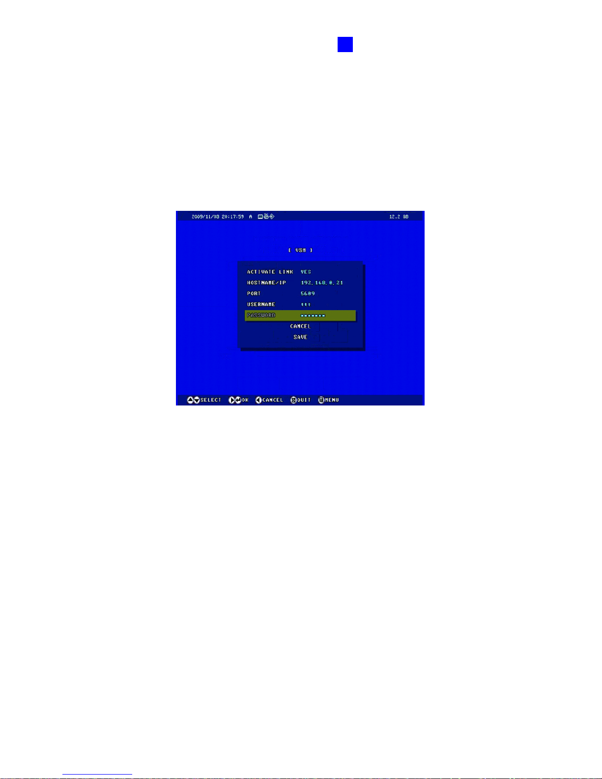
OSD Menu Configurations
69
4
4.3.4 VSM
After a motion or an I/O triggered event, the central monitoring station VSM can get notified by
text alerts. For the monitoring through VSM, you must already have a subscriber account on
VSM.
You can connect up to two VSM servers for central monitoring. Press CH1 and CH2 buttons
on the Remote Control for two different connection settings.
Figure 4-21
ACTIVATE LINK: Enable the monitoring through VSM for alert events.
HOSTNAME/IP: Enter the host name or IP address of VSM.
PORT: Enter the port matching the Port 2 on VSM. Or keep the default value 5609. Refer
to 11.2 VSM.
USER NAME: Enter a valid user name to log into VSM.
PASSWORD: Enter a valid password to log into VSM.
Using the Web interface, you can set up the connection schedule. For more information and
features of the VSM connection, see 6.3.4 VSM of the Web-based configuration.
.
Page 79
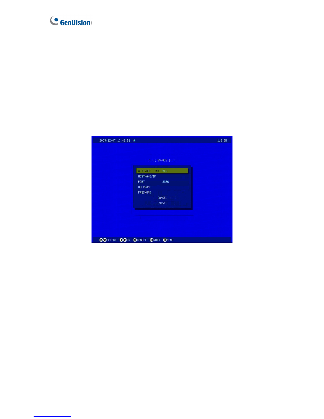
70
4.3.5 GV-GIS
Note the GV-GIS function is only supported on Anti-Vibration ACC models (GV-LX4C3V,
GV-LX8CV1 and GV-LX8CV2).
Through the network connection, the Anti-Vibration ACC models equipped with GPS devices
can send GPS data and live video to the GV-GIS (Geographic Information System) for the
services of vehicle tracking, location verification and live monitoring.
You can connect up to two GV-GIS servers for central monitoring. Press CH1 and CH2
buttons on the Remote Control for two different connection settings.
Figure 4-22
ACTIVATE LINK: Enable the monitoring through GV-GIS.
HOSTNAME/IP: Enter the host name or IP address of GV-GIS.
PORT: Enter the port matching that on GV-GIS. Or keep the default value 5609.
USER NAME: Enter a valid user name to log into GV-GIS.
PASSWORD: Enter a valid password to log into GV-GIS.
Using the Web interface, you can set up the connection schedule. For more information and
features of the GV-GIS connection, see 6.3.5 GV-GIS of the Web-based configuration.
Page 80
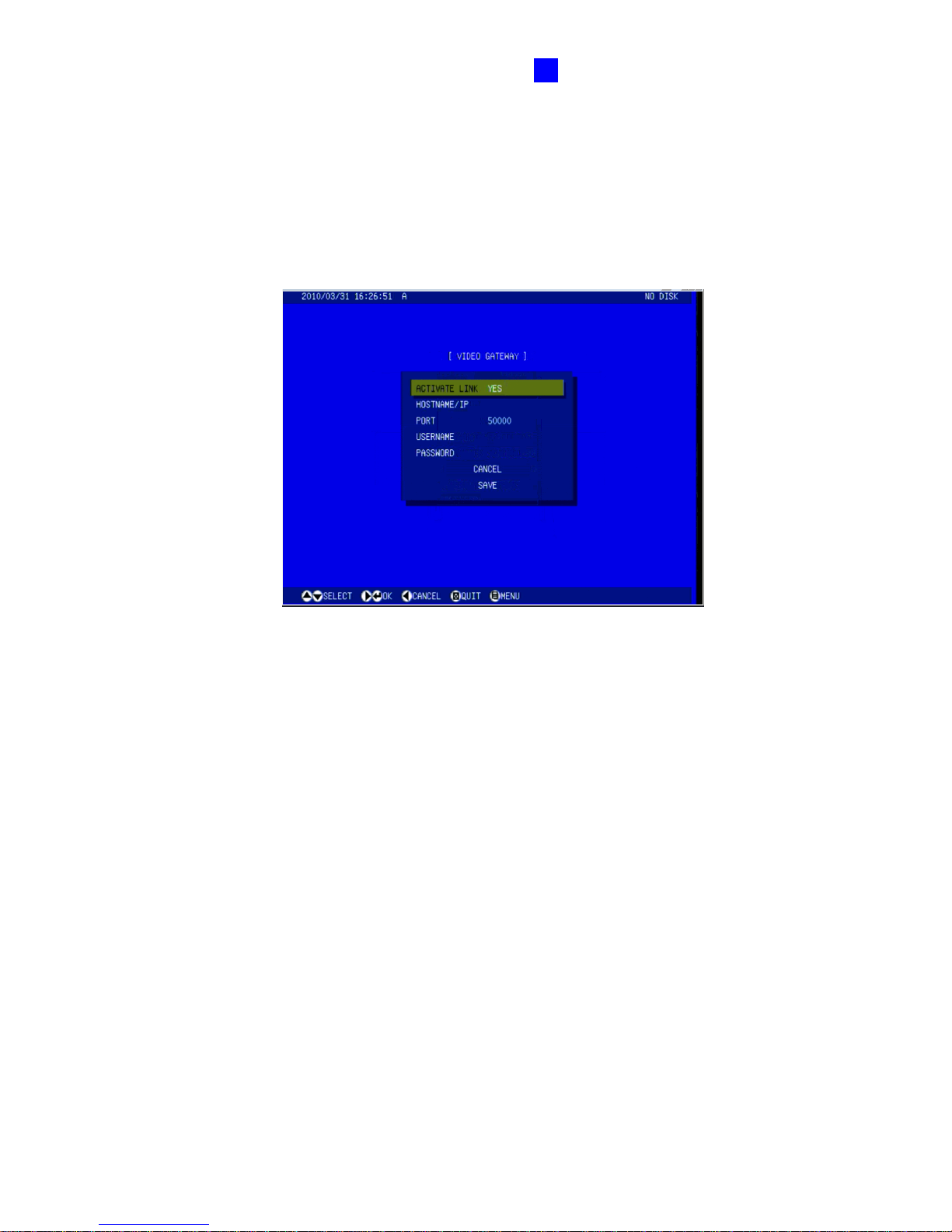
OSD Menu Configurations
71
4
4.3.6 Video Gateway / Recording Server
You can send the video images to the GV-Video Gateway or GV-Recording Server.
Up to two GV-Video Gateways or GV-Recording Servers can be connected with the unit..
Press CH1 and CH2 buttons on the Remote Control for two different connection settings.
Figure 4-23
Activate Link: Enable the connection to the GV-Video Gateway or GV-Recording Server.
HOSTNAME/IP: Enter the host name or IP address of GV-Video Gateway or
GV-Recording Server.
PORT: Enter the port matching that on GV-Video Gateway or GV-Recording Server. Or
keep the default value 50000.
USER NAME: Enter a valid user name to log into GV-Video Gateway or GV-Recording
Server.
PASSWORD: Enter a valid password to log into GV-Video Gateway or GV-Recording
Server.
Using the Web interface, you can set up the connection schedule. For more information and
features of the GV-Video Gateway and GV-Recording Server connection, see 6.3.7 Video
Gateway / Recording Server of the Web-based configuration.
Page 81
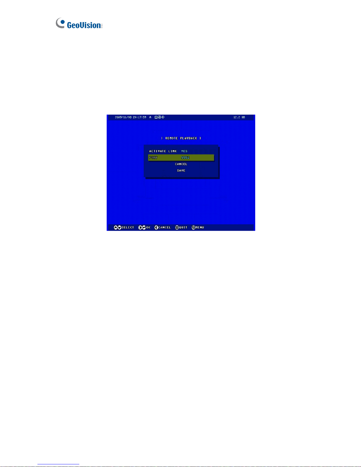
72
4.3.7 Remote Playback
You can remotely access and play the recorded files saved on the GV-Compact DVR V3
Select YES to activate the remote playback server built in the unit and to allow playback
access. Keep the default port 5552 or modify it if necessary. For details on the remote
playback, see 7.2.2 Playback over Network.
Figure 4-24
Page 82
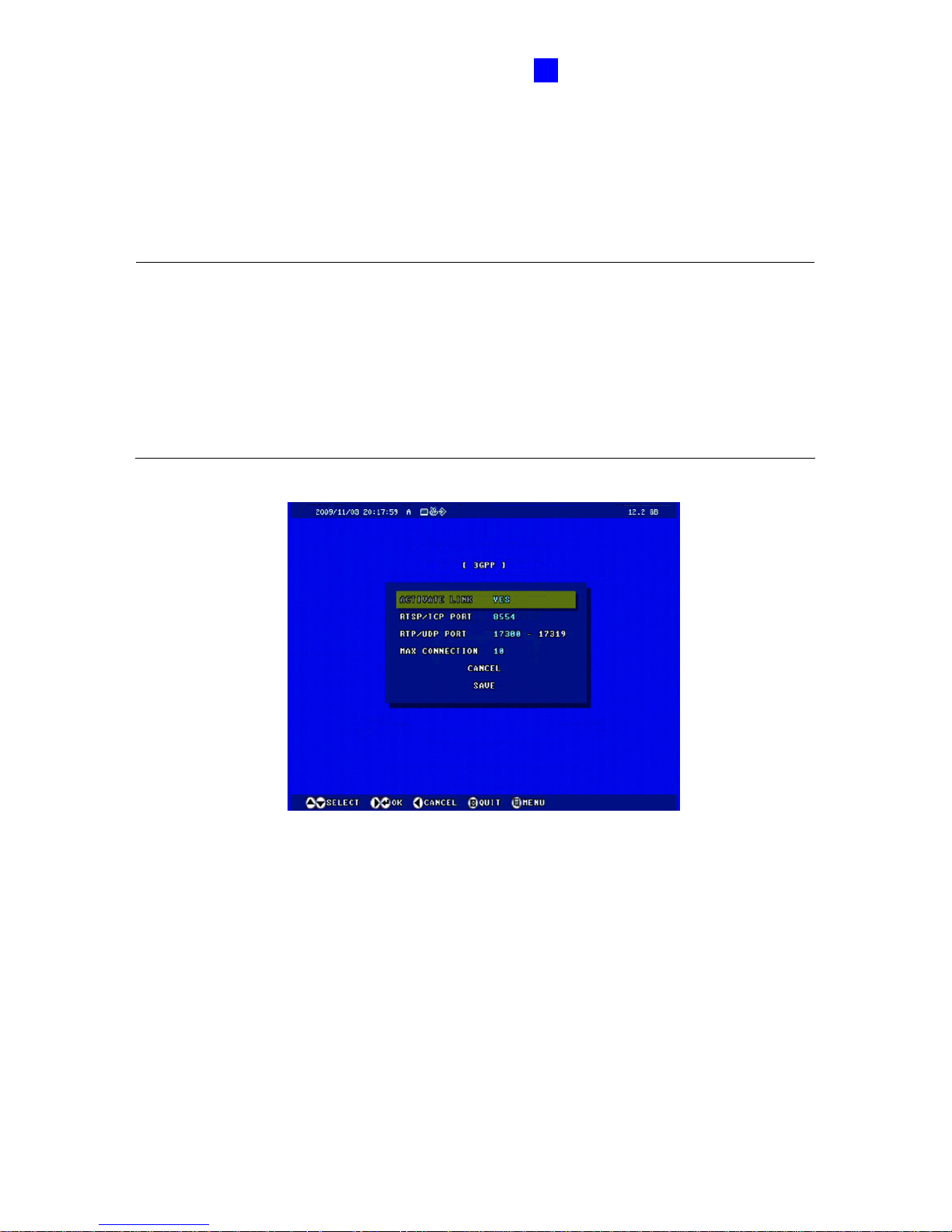
OSD Menu Configurations
73
4
4.3.8 3GPP
The 3GPP server allows you to enable the Real Time Stream Protocol (RTSP) and watch live
streaming by using VLC or QuickTime player. For the RTSP command, see RTSP Protocol
Support in Appendix E.
Note:
1. Currently the GV-Compact DVR V3 does not support 3GPP mobile connection.
2. In four-channel models, you can only enable either RTSP or Multicast; the two protocols
cannot function at the same time.
3. In eight-channel modes, when 3GPP server (RTSP protocol) is enabled, you cannot
access the live view through the Web interface at the same time.
Figure 4-25
ACTIVATE LINK: Enable the RTSP protocol.
RTSP/TCP PORT: Keep the default value 8554, or modify it if necessary.
RTP/UDP PORT: Keep the default range from 17300 to 17319, or modify it if necessary.
The number of ports for use is limited to 20.
MAX CONNECTION: Set the maximum number of RTSP connections to the GV-Compact
DVR V3. The maximum value is 20.
Page 83
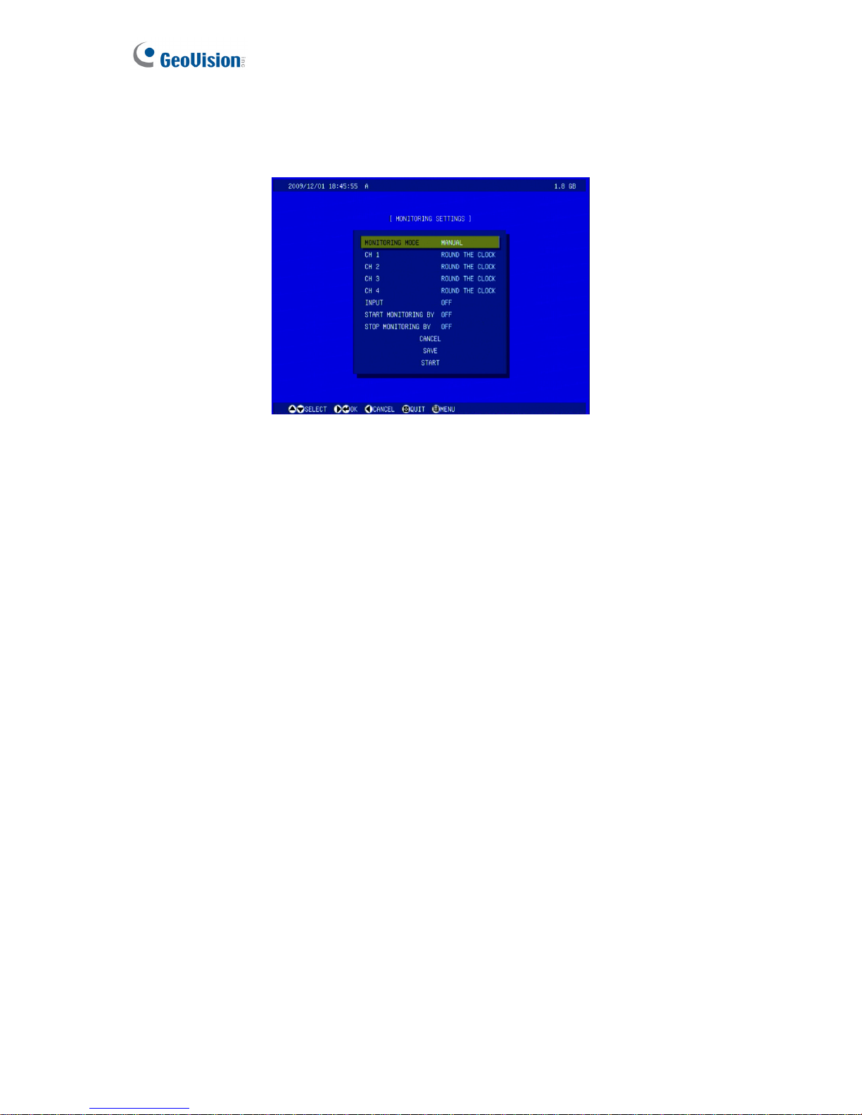
74
4.4 Monitoring Settings
You can start recording manually, by schedule or by input trigger.
Figure 4-26
MONITORING MODE:
~ Select MANUAL to manually start recording or I/O monitoring. If you choose this
option, configure the following item CHANNEL (CH 1 – CH 4 for the four-channel unit,
or CH 1 – CH 8 for the eight-channel unit) or INPUT.
~ Select SCHEDULE to start recording and I/O monitoring by the schedule you set up.
To configure recording schedule, see 4.5 Recording Schedule.
CHANNEL: Available only in MANUAL monitoring mode. Select the desired channel (CH
1 – CH 4 for the four-channel unit, or CH 1 – CH 8 for the eight-channel unit), and set its
recording mode to be motion detection or round-the-clock. You can also select to turn off
the channel for monitoring.
INPUT: Available only in MANUAL monitoring mode. Select ON to start I/O monitoring
manually. When the input is triggered, its associated cameras and outputs will also be
enabled for recording and alerting. For input settings, see 4.2.1 Digital Input Settings.
START MONITORING BY: Start monitoring with a triggered input. When the assigned
input is triggered, the system will response based on your settings in either MANUAL or
SCHEDULE monitoring mode.
STOP MONITORING BY: Stop monitoring with a triggered input. When the assigned input
is triggered, the system will stop monitoring.
Page 84

OSD Menu Configurations
75
4
To start monitoring or recording:
• Select START. The unit will start monitoring based on your above settings: record
immediately, only record on the scheduled time, or record by an input trigger.
• Select SAVE to save the monitoring settings. Then press the REC button on the Remote
Control at any time to start your monitoring settings.
Also see 6.4 Monitoring of the Web-based configuration which provides more information and
features of the monitoring settings.
Page 85
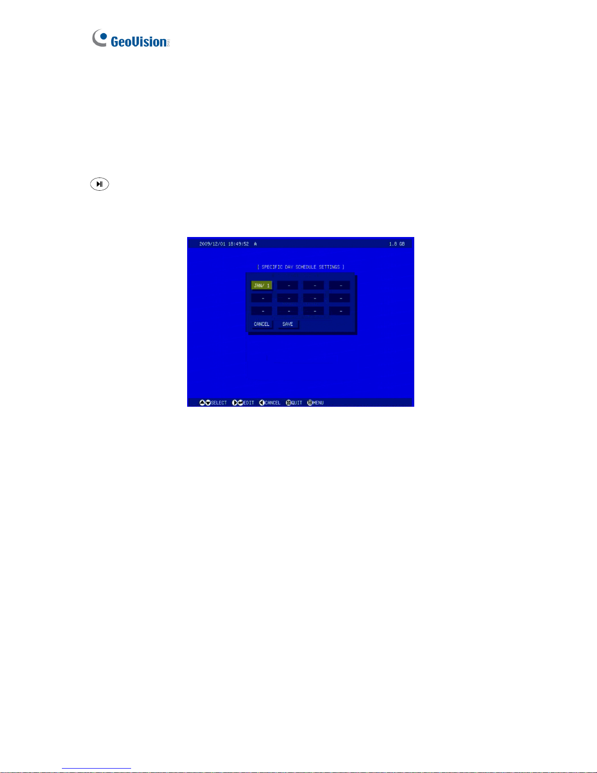
76
4.5 Recording Schedule
The schedule is provided to activate recording and I/O monitoring on a specific time each day.
4.5.1 Specific Day
The system will operate automatically on the specific days you have scheduled. Press the
button on the Remote Control to start setting and then use the directional buttons to
define the days. To enable the camera and I/O monitoring on the defined days, see SPECIFIC
DAY options in 4.5.2 Channel Schedule and 4.5.3 I/O Monitoring Schedule.
Figure 4-27
Page 86
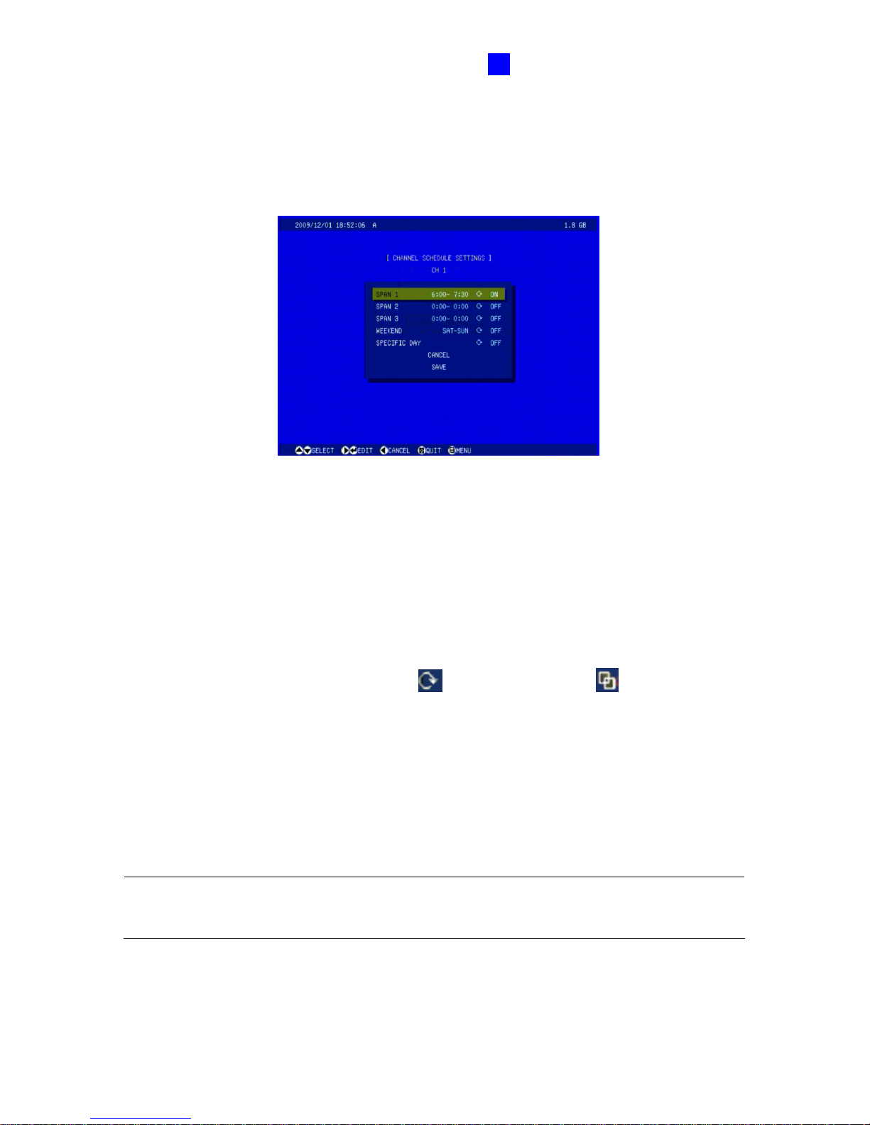
OSD Menu Configurations
77
4
4.5.2 Channel Schedule
You can set up different monitoring schedules for each camera. Press the Channel button
(CH1 – CH4 for the four-channel unit; CH1 – CH8 for the eight-channel unit) on the Remote
Control to select one channel for setup.
Figure 4-28
Span 1- Span 3: Sets different recording modes for each time frame during the day. Each
day can be divided into 3 time frames, represented by Span 1 to Span 3.
Weekend: If you want to have the camera monitoring all day during the weekend, enable
this option and select the recording mode to be used on the weekend. Define whether your
weekend includes Saturday and Sunday (SAT-SUN) or Only Sunday (SUN).
Recording mode: round-the-clock icon , motion detection icon .
Specific Day: Enable the camera monitoring only on the specified days. To set the
specific days, see 4.5.1 Specific Day.
To start the scheduled recording, you must set the monitoring mode to be SCHEDULE. See
4.4 Monitoring Settings.
Note: The recording mode you set will be indicated on the main screen when the monitoring
is started. For details, see 3.8 Main Screen Overview.
Page 87
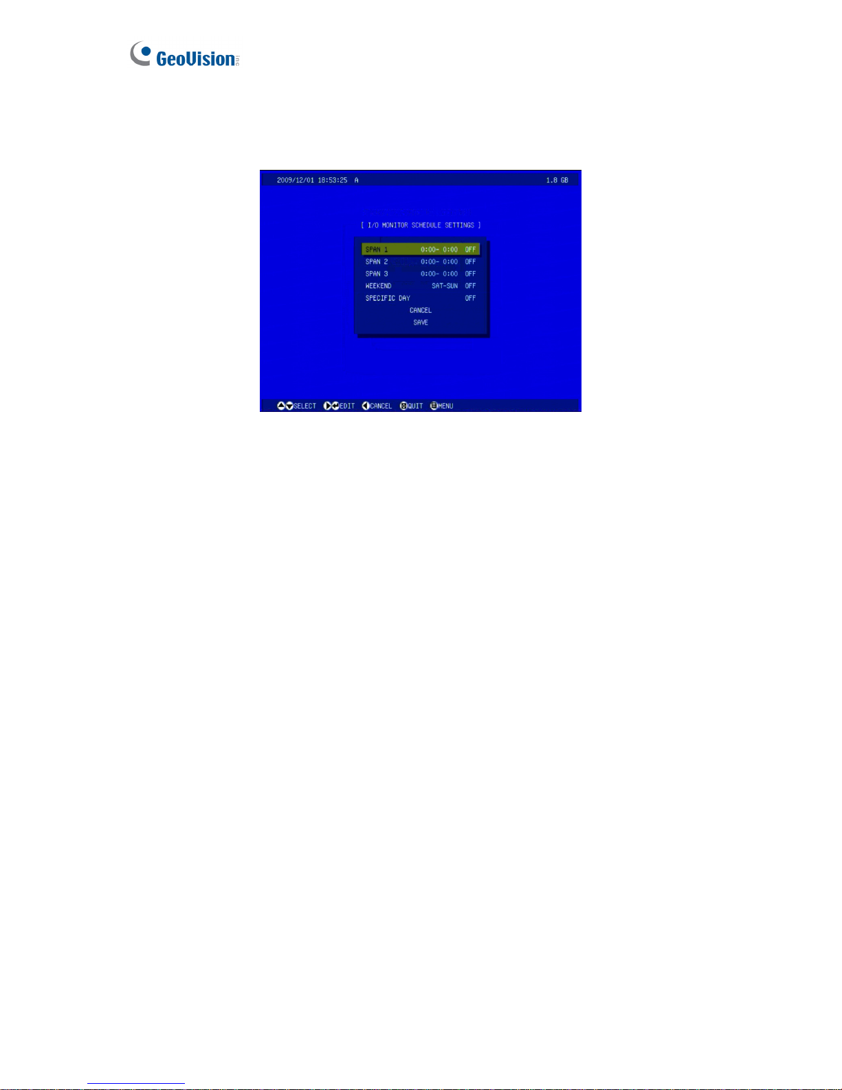
78
4.5.3 I/O Monitoring Schedule
You can set up the schedule for I/O monitoring to start.
Figure 4-29
Span 1- Span 3: Set different time frames during the day to enable I/O monitoring. Each
day can be divided into 3 time frames, represented by Span 1 to Span 3.
Weekend: If you want to have the I/O monitoring all day during the weekend, enable this
option and define whether your weekend includes Saturday and Sunday (SAT-SUN) or
Only Sunday (SUN).
Specific Day: Enable the I/O monitoring only on the specified days. To set the specific
days, see 4.5.1 Specific Day.
To start the scheduled recording, you must set the monitoring mode to be SCHEDULE. See
4.4 Monitoring Settings.
Page 88
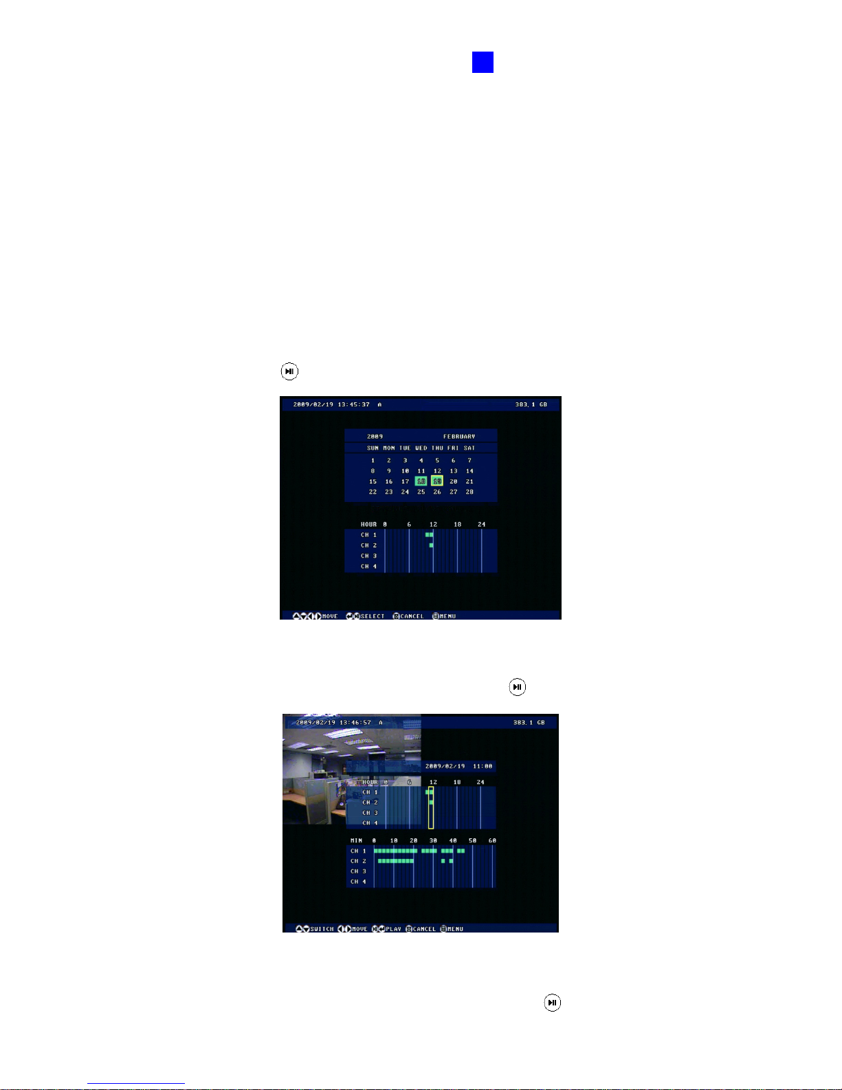
OSD Menu Configurations
79
4
4.6 Search / Playback
You can retrieve the recorded video by date, time and event. To access the
SEARCH/PLAYBACK menu, press the Menu button or the Search button on the Remote
Control.
4.6.1 Time Map List
The Time Map List provides an overview of the recorded videos in the form of a calendar.
1. On the calendar, dates for which there are recorded videos are green. Use the directional
buttons on the Remote Control to move the focus, and select the desired Year, Month and
Day. Then press the
button.
Figure 4-30
2. In the HOUR section, hours for which there are recorded videos are green. Each column
represents 1 hour. Select the desired hour and press the
button.
Figure 4-31
3. In the MIN section, minutes for which there are recorded videos are green. Each column
represents 2 minutes. Select the desired minute and press the
button to start playback.
Page 89

80
4.6.2 List All
The list displays a complete list of recorded videos. To move the list screen up and down one
page, press the right and left directional buttons on the Remote Control. To start playback,
highlight the desired video and press the
button.
4.6.3 Manual Recording List
The list displays a complete list of manually recorded videos. To move the list screen up and
down one page, press the right and left directional buttons on the Remote Control. To start
playback, highlight the desired video and press the
button.
4.6.4 Alarm Recording List
The list displays a complete list of recorded videos on input trigger. To move the list screen up
and down one page, press the right and left directional buttons on the Remote Control. To
start playback, highlight the desired video and press the
button.
4.6.5 Motion Recording List
The list displays a complete list of recorded videos on motion detection. To move the list
screen up and down one page, press the right and left directional buttons on the Remote
Control. To start playback, highlight the desired video and press the
button.
4.6.6 Time Search
You can locate the recorded videos within a certain date and time. Enter START TIME and
END TIME for the time search. Then define how to display the found videos. Select LIST to
display a list of found videos, or PLAY for immediate playback.
Page 90
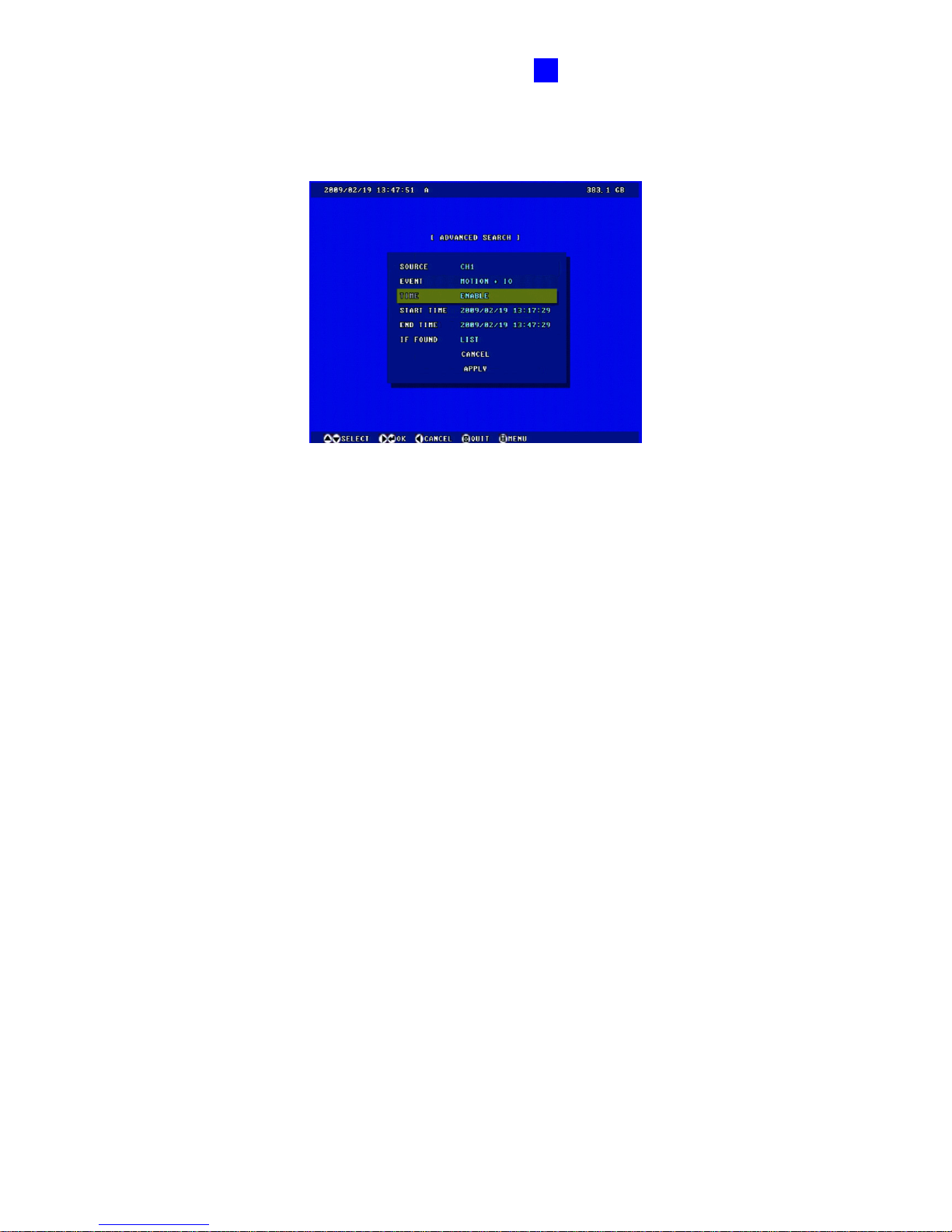
OSD Menu Configurations
81
4
4.6.7 Advanced Search
You can limit your search by defining search criteria.
Figure 4-32
SOURCE: Search the recorded video from the selected channel or all channels.
EVENT: Select the type of recorded videos with the options of motion detection and input
trigger (MOTION + IO), motion detection (MOTION), any input triggered (ALL IO) or an
individual input triggered (e.g. IO 1 for input 1 triggered).
TIME: Enable this option to define a period of time.
START TIME: Set the starting time of the video search.
END TIME: Set the ending time of the video search.
IF FOUND: Set how to display the found videos. Select LIST to display a list of found
videos, or PLAY for immediate playback.
Page 91
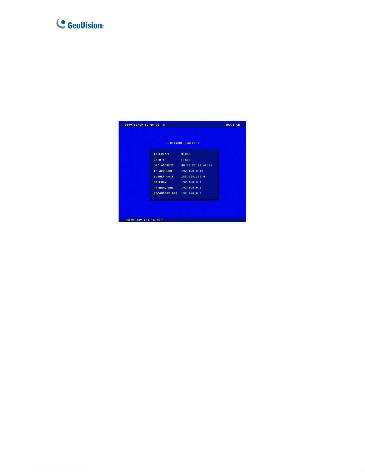
82
4.7 Network
The GV-Compact DVR V3 allows you to use a Web browser to remotely view and manage the
system. For remote access, configure the related network settings in this section.
4.7.1 Network Status
The Network Status displays the current network settings of GV-Compact DVR V3.
Figure 4-33
Page 92
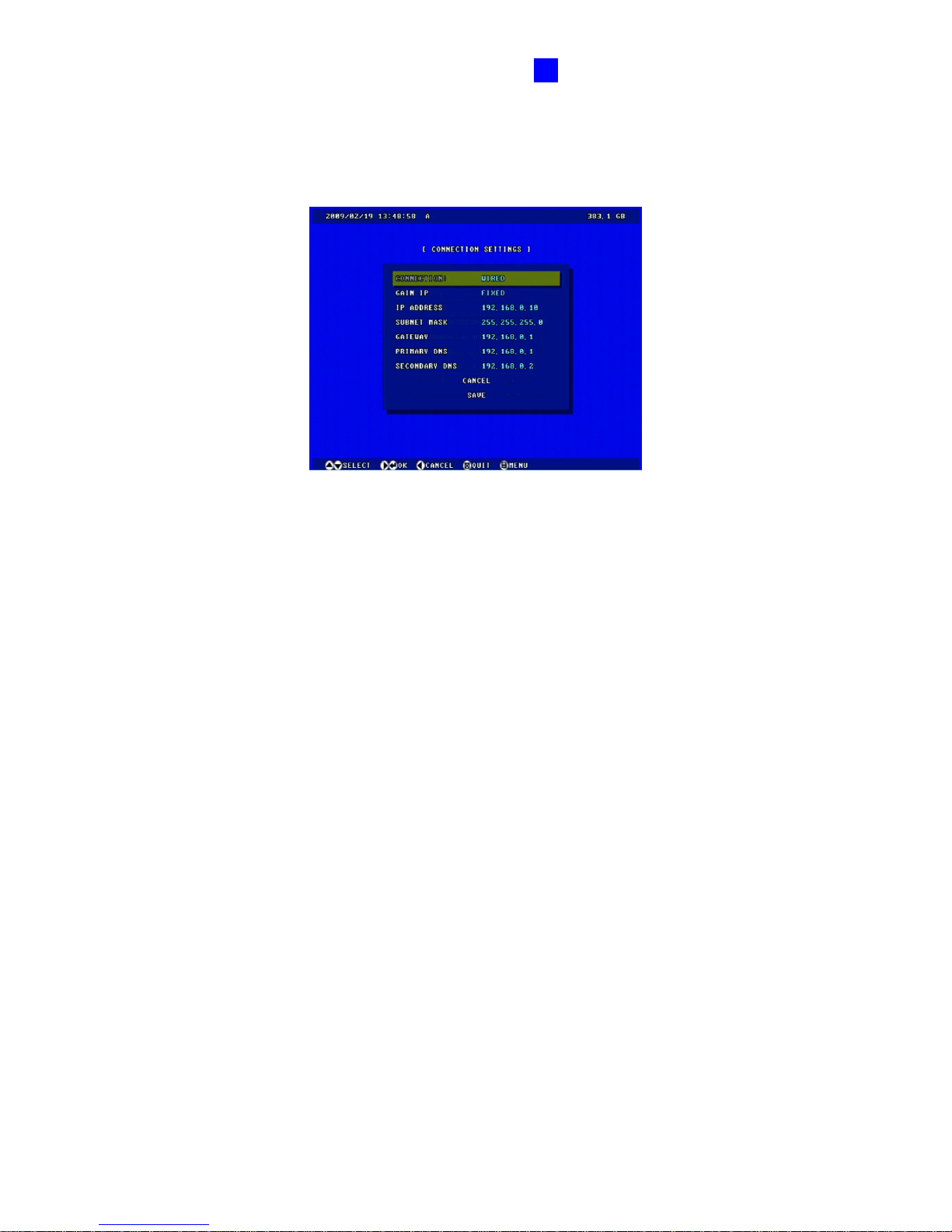
OSD Menu Configurations
83
4
4.7.2 Connection Settings
According to your network environment, select among Static IP, DHCP and PPPoE to
configure an IP address to the GV-Compact DVR V3.
Figure 4-34
CONNECTION: According to the network environment, select WIRED or WIRELESS.
Before enabling WIRELESS, configure WIRELESS SETTINGS which is explained in the
following section.
GAIN IP:
~ FIXED: Assign a static IP or fixed IP to the GV-Compact DVR V3. Enter the
GV-Compact DVR V3’s static IP address, subnet mask, gateway, primary DNS and
secondary DNS.
~ DHCP: Assign a dynamic IP by the DHCP server. If this option is enabled, you must
check the current IP assigned by the DHCP server at the Network Status screen
every time before logging in the unit. In this case, it is suggested to use the DDNS
function to get a domain name that always links to the unit’s changing IP address. To
enable the DDNS function, see 4.7.6 DDNS Settings.
~ PPPoE: The Network environment is xDSL connection. Enter the username and
password provided by ISP to establish the connection. If you use the xDSL
connection with dynamic IP addresses, it is highly suggested to enable the DDNS
function that links a domain name to the unit’s changing IP address. To enable the
DDNS function, see 4.7.6 DDNS Settings.
Page 93
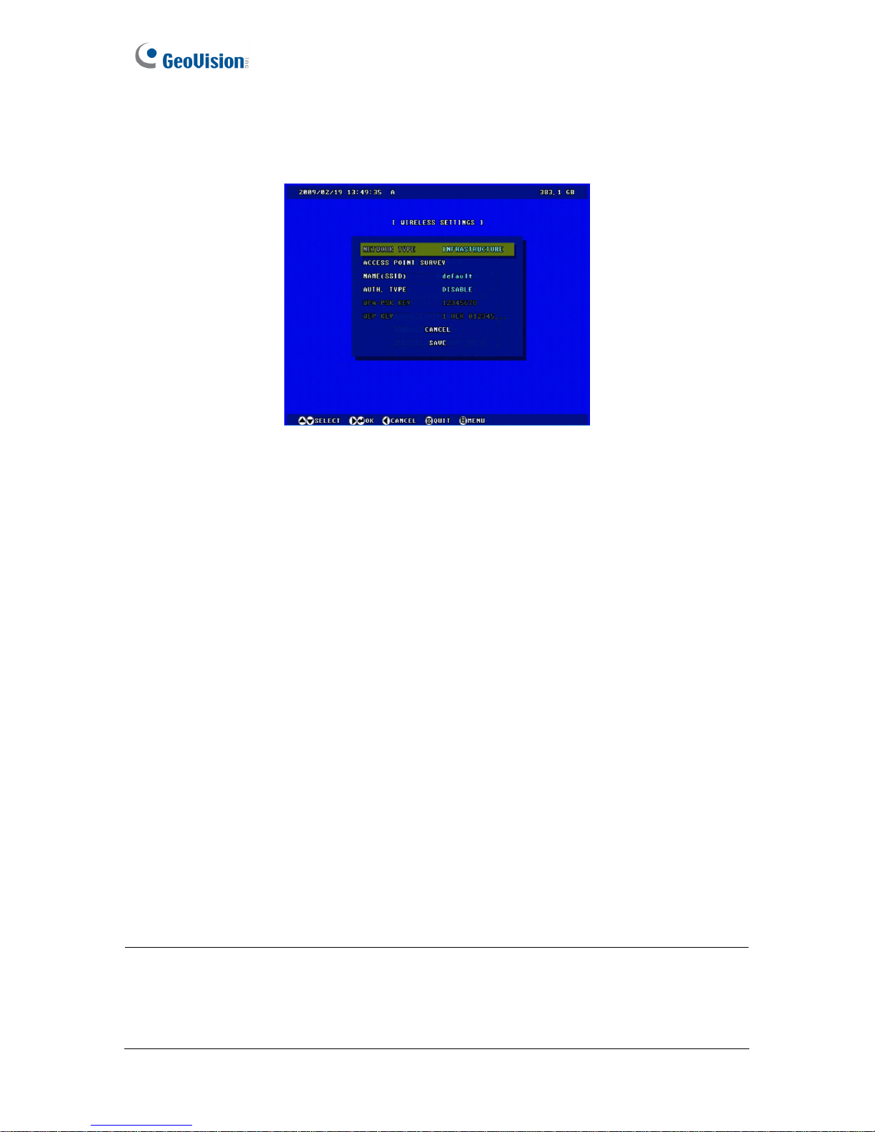
84
4.7.3 Wireless Settings
To use the wireless function, a wireless LAN USB Adaptor is required. For supported wireless
LAN adaptors, see Appendix A.
Figure 4-35
NETWORK TYPE: Select AD HOC or INFRASTRUCTURE for the network mode.
~ AD HOC: A Peer-to-Peer mode. This mode connects to other computer with the
WLAN card, and does not need the Access Point to connect to each other.
~ INFRASTRUCTURE: Via the Access Point to connect to the Internet. This mode
further gives wireless access to the Internet or data sharing under a previously wired
environment.
ACCESS POINT SURVEY: Search all the available Access Points (Infrastructure mode)
and wireless stations (AD-Hoc mode) within the range of your WLAN card.
NAME (SSID): The SSID (Service Set Identity) is a unique name that identifies a particular
wireless network. Enter SSID of the Wireless LAN group or Access Point you are going to
connect to.
AUTH. TYPE: Select one of these network authentication and data encryption: DISABLE,
WEP, WPASPSK-AES, WPA2PSK-TKIP or WPA2PSK-AES.
~ WEP: Abbreviated for Wired Equivalent Privacy, this is a type of data encryption.
Type up to 4 WEP keys in HEX or ASCII format. Note that if you use HEX format, only
digits 0-9, letters A-F and a-f are valid.
~ WPASPSK-AES or WPA2PSK-AES: Type WPA-PSK (Pre-Shared Key) for data
encryption.
~ WPA2PSK-TKIP: Type WPA-PSK (Pre-Shared Key) for data encryption.
Note:
1. Your encryption settings must match those used by the Access Points or wireless
stations with which you want to associate.
2. When you lose the wireless access, you can still access the unit by connecting it to a
LAN and logging in with the default IP address 192.168.0.10.
Page 94
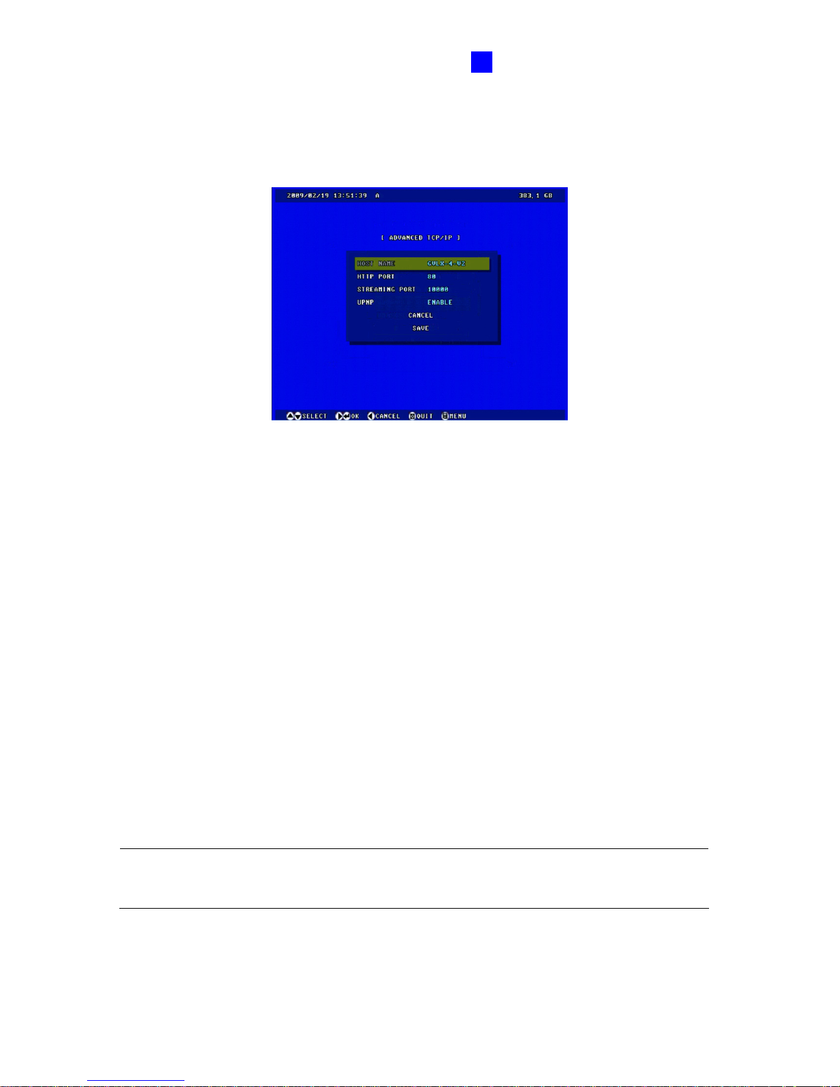
OSD Menu Configurations
85
4
4.7.4 Advanced TCP/IP
You can set up the advanced TCP/IP settings, including DDNS server, HTTP port, streaming
port and UPnP.
Figure 4-36
HOST NAME: Enter a descriptive name for the GV-Compact DVR V3.
HTTP PORT: The HTTP port enables connecting the GV-Compact DVR V3 to the Web.
For security integration, the Administrator can hide the server from the general HTTP port
by changing the default HTTP port of 80 to a different port number within the range of
1024 thru 65535.
STREAMING PORT: The port enables connecting the GV-Compact DVR V3 to the
GV-System. The default setting is 10000.
UPNP: UPnP (Universal Plug & Play) is a networking architecture that provides
compatibility among networking equipment, software and peripherals of the 400+ vendors
that are part of the Universal Plug and Play Forum. It means that they are listed in the
network devices table for the operating system (such as Windows XP) supported by this
function. Enabling this function, you can connect to the GV-Compact DVR V3 directly by
clicking on the GV-Compact DVR V3 listed in the network devices table.
Note: The GV-Compact DVR V3 also supports HTTPS and QoS protocols. For these
protocol settings, see 6.7.3 Advanced TCP/IP of the Web-based configuration.
Page 95
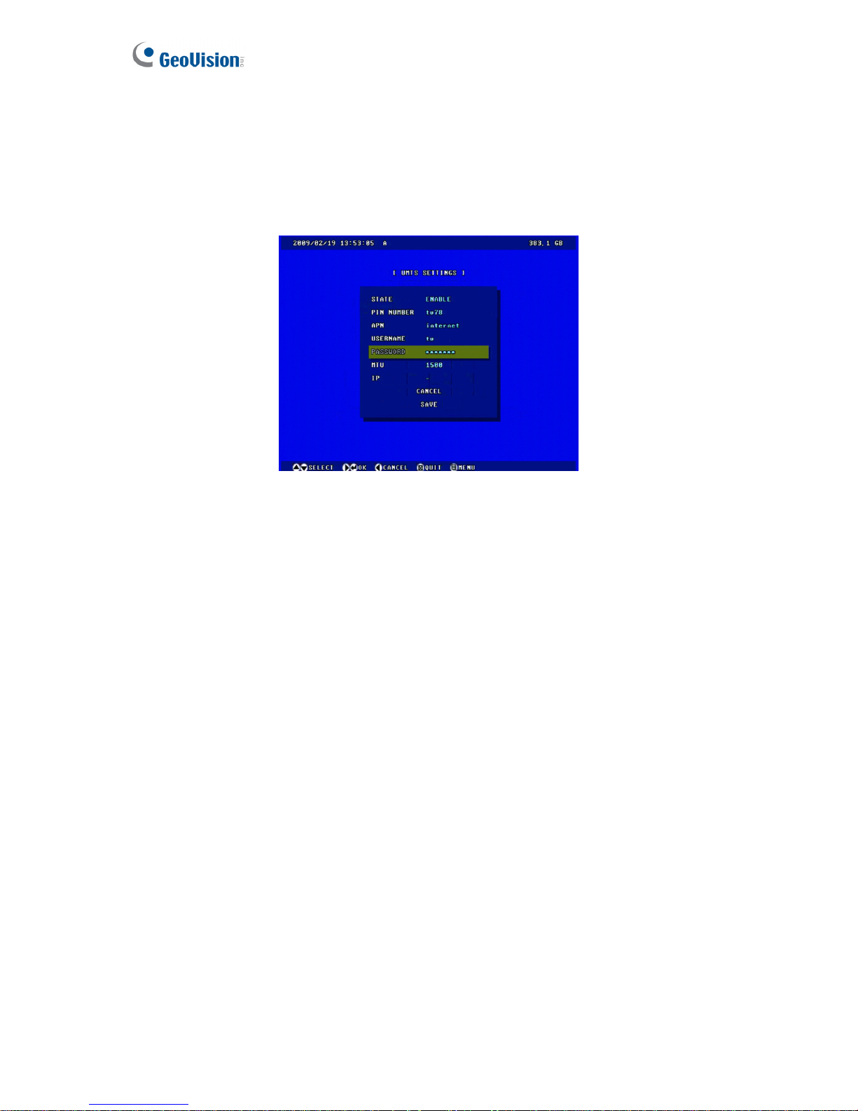
86
4.7.5 UMTS Settings
After a mobile broadband device (supporting UMTS, HSDPA and etc) is attached to the USB
port on the GV-Compact DVR V3 and the UMTS function is enabled, the GV-Compact DVR
V3 can have Internet connectivity. For the supported mobile broadband devices, see
Appendix B.
Figure 4-37
STATE: Enable the UMTS function.
PIN NUMBER: Enter the PIN number that is provided by your network operator.
APN: Enter the Access Point Name (APN) that is provided by your network operator.
USERNAME: Enter a valid username to enable the UMTS service from your network
operator.
PASSWORD: Enter a valid password to enable the UMTS service from your network
operator.
MTU: Enter the Maximum Transfer Unit (MTU). The default vale is 1500.
IP Address: The IP address of the GV-Compact DVR V3 will be displayed after the
UMTS service is enabled. The next time when you want to log in the GV-Compact DVR
V3, you need to enter the IP address into your browser. If you use the UMTS connection
with dynamic IP addresses, it is highly suggested to enable the DDNS function that links
a domain name to the unit’s changing IP address. For details on DDNS, see 4.7.6 DDNS
Settings.
Also see 6.7.4 UMTS/ZigBee of the Web-based configuration which provides more
information and features of the UMTS connection.
Page 96
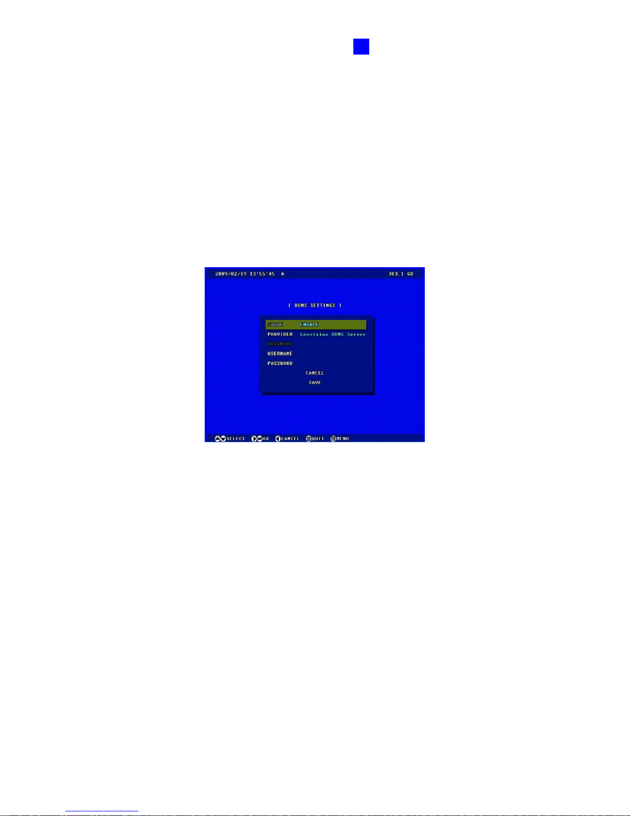
OSD Menu Configurations
87
4
4.7.6 DDNS Settings
DDNS (Dynamic Domain Name System) provides a convenient way of accessing the
GV-Compact DVR V3 when using a dynamic IP. DDNS assigns a domain name to the unit, so
that the Administrator does not need to go through the trouble of checking if the IP address
assigned by DHCP server or ISP (in xDSL connection) has changed.
Before enabling the DDNS function, the Administrator should apply for a Host Name from the
DDNS service provider’s website. There are 2 providers listed on the GV-Compact DVR V3:
GeoVision DDNS Server (http://ns.dipmap.com/register.aspx) and DynDNS.org
(http://www.dyndns.com/).
Figure 4-38
STATE: Enable the DDNS function.
PROVIDER: Select the DDNS service provider you have registered with.
HOSTNAME: Enter the host name used to link to the GV-Compact DVR V3. For the
users of GeoVision DDNS Server, it is unnecessary to fill the field because the system
will detect the host name automatically.
USERNAME: Enter a valid user name used to enable the service from the DDNS.
PASSWORD: Enter a valid password used to enable the service from the DDNS.
Page 97
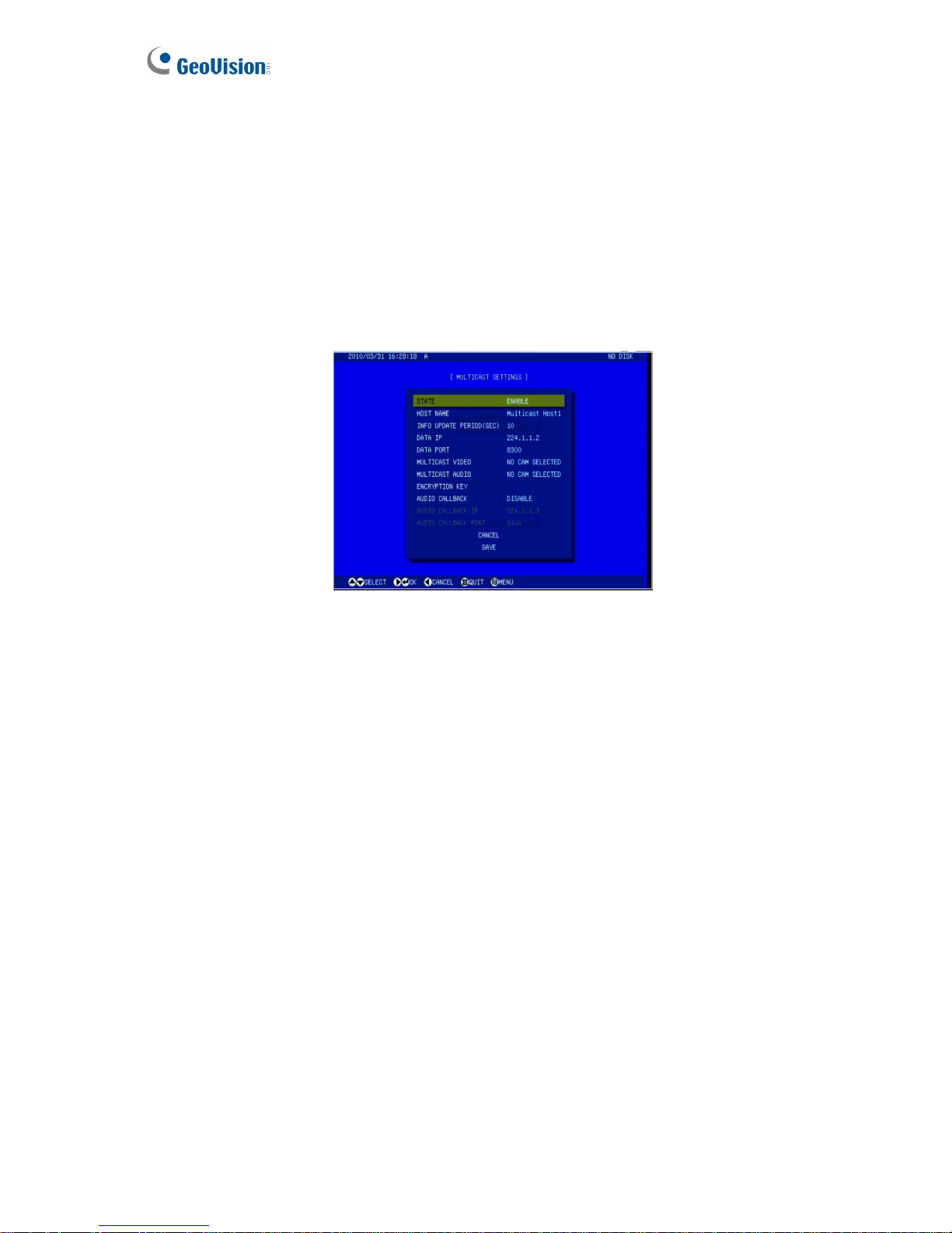
88
4.7.7 Multicast Settings
Note the Multicast function is only supported on the four-channel GV-Compact DVR V3 and
only works on a single stream. You can enable either Multicast or RTSP; the two protocols
cannot function at the same time.
The multicast provides a mechanism for sending a single video and audio stream to a group
of hosts. Only the hosts that have joined a multicast group can send and receive the multicast
streams. The multicast streams are only sent to the hosts on a local network.
Figure 4-39
STATE: Enable the Multicast function.
HOST NAME: Name the GV-Compact DVR V3 in a multicast group.
INFO UPDATE PERIOD: Enter the time length between each update of multicast
streams.
DATA IP: Enter the IP address used for multicasting. The default IP address is 224.1.1.2.
DATA PORT: Enter the port used for multicasting. The default value is 8300.
MULTICAST VIDEO: Select the camera to send its video through multicasting.
MULTICAST AUDIO: Select the audio to send its audio through multicasting.
ENCRYPTION KEY: Enter an Encryption Key to secure multicast streams. The hosts in
the multicast group will need to enter the Key to access the video and audio streams.
AUDIO CALLBACK: Enable this option to receive audio broadcasting from the hosts in
the multicast group. Specify the IP address and port number to receive the audio
broadcast. The default IP address is 224.1.1.3 and port number is 8400.
Also see 6.7.5 Multicast of the Web-based configuration which provides more information and
features of the Multicast function.
Page 98
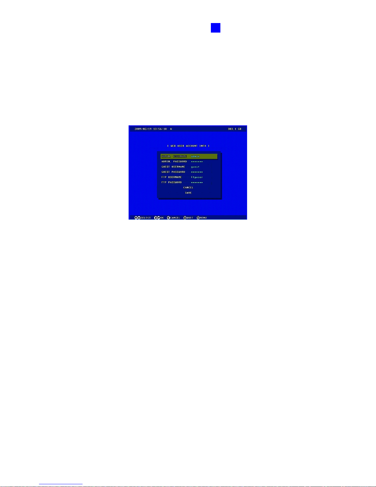
OSD Menu Configurations
89
4
4.7.8 Web User Account Info
You can change the login name and password of Administrator, Guest and FTP Server User.
• The default Administrator login name and password are admin.
• The default Guest login name and password are guest.
• The default FTP Server login name and password are ftpuser.
Figure 4-40
Page 99
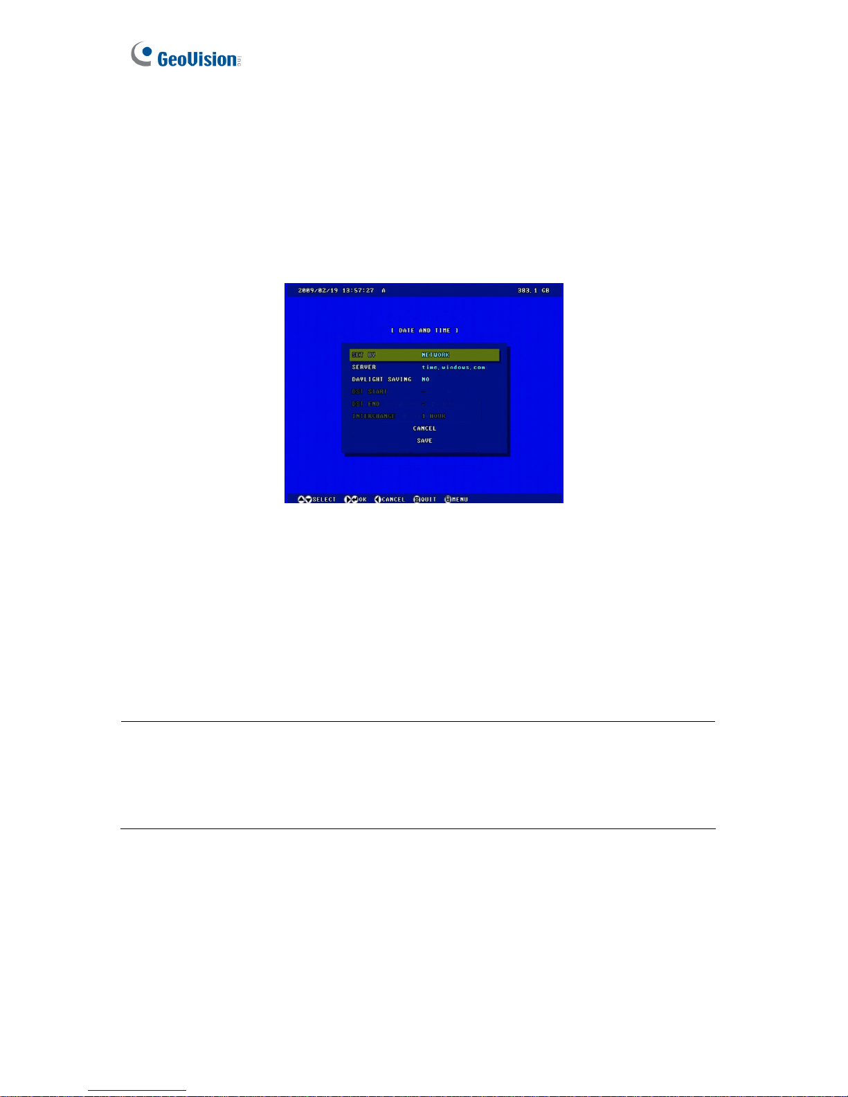
90
4.8 Advanced
In this section, you can configure the settings of date and time, storage device, screen display,
and system password. In addition, you can view and upgrade the firmware.
4.8.1 Date and Time
The date and time settings are used for date and time stamps on the image.
Figure 4-41
SET BY: Select MANUAL to adjust the data and time by yourself, or NETWORK to
synchronize the date and time with a time server. If you select NETWORK, then the option
of SERVER appears. Use the on-screen keypad to enter the IP address of the time server.
DAY LIGHT SAVING: Automatically adjust the GV-Compact DVR V3 for daylight saving
time. Enter the Start and End time of daylight saving.
Note: The default setting with the time server can avoid the system time delay. If your
GV-Compact DVR is not networked or the time server is not enabled, the system time may
delay about 1.5 second every 24 hours. In such case, you could update the system time
manually to ensure exact recording time.
Also see 7.2.4 Playback of Backup Files of the Web-based configuration which provides more
information and features of the date and time settings.
Page 100
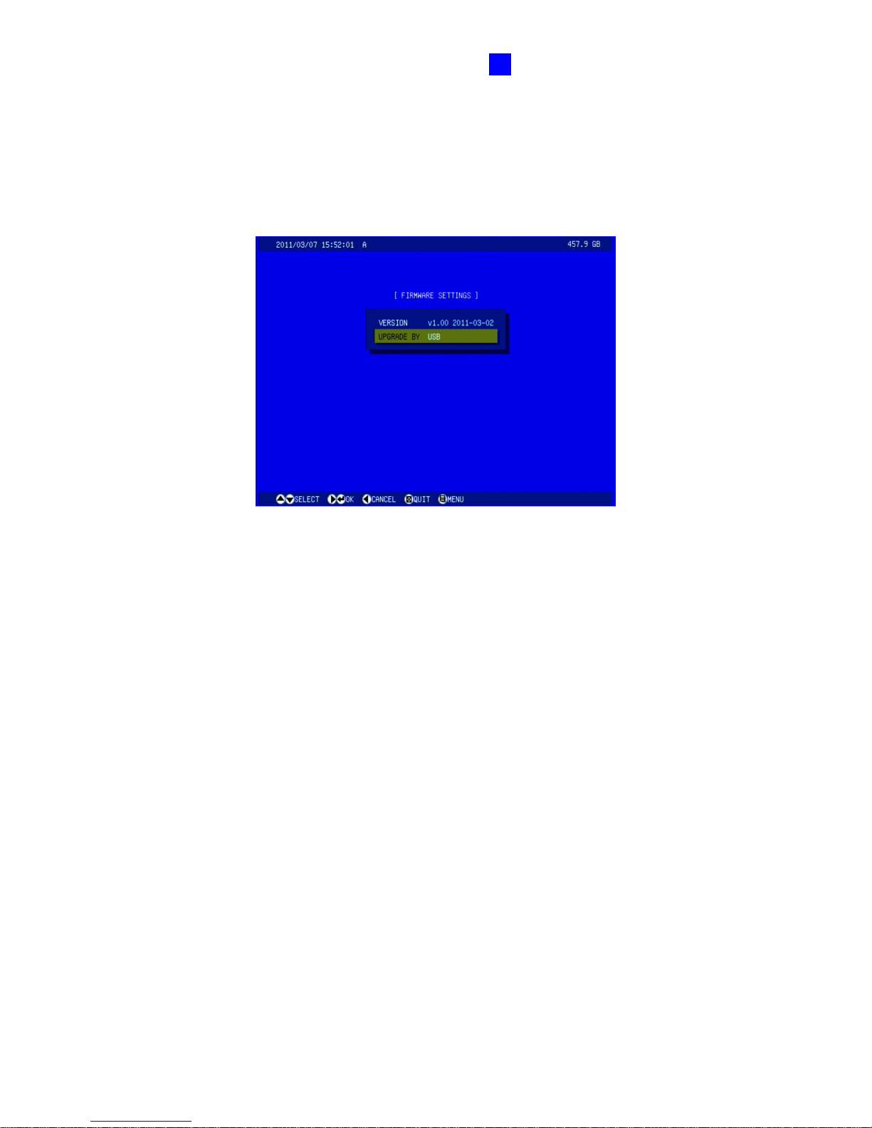
OSD Menu Configurations
91
4
4.8.2 Firmware Settings
GeoVision will periodically release the updated firmware on the website. The new firmware
can be simply loaded into the GV-Compact DVR V3 by using a USB storage device.
For the details on upgrading the unit over the network, see Chapter 8 Advanced Applications.
Figure 4-42
 Loading...