

Page 1
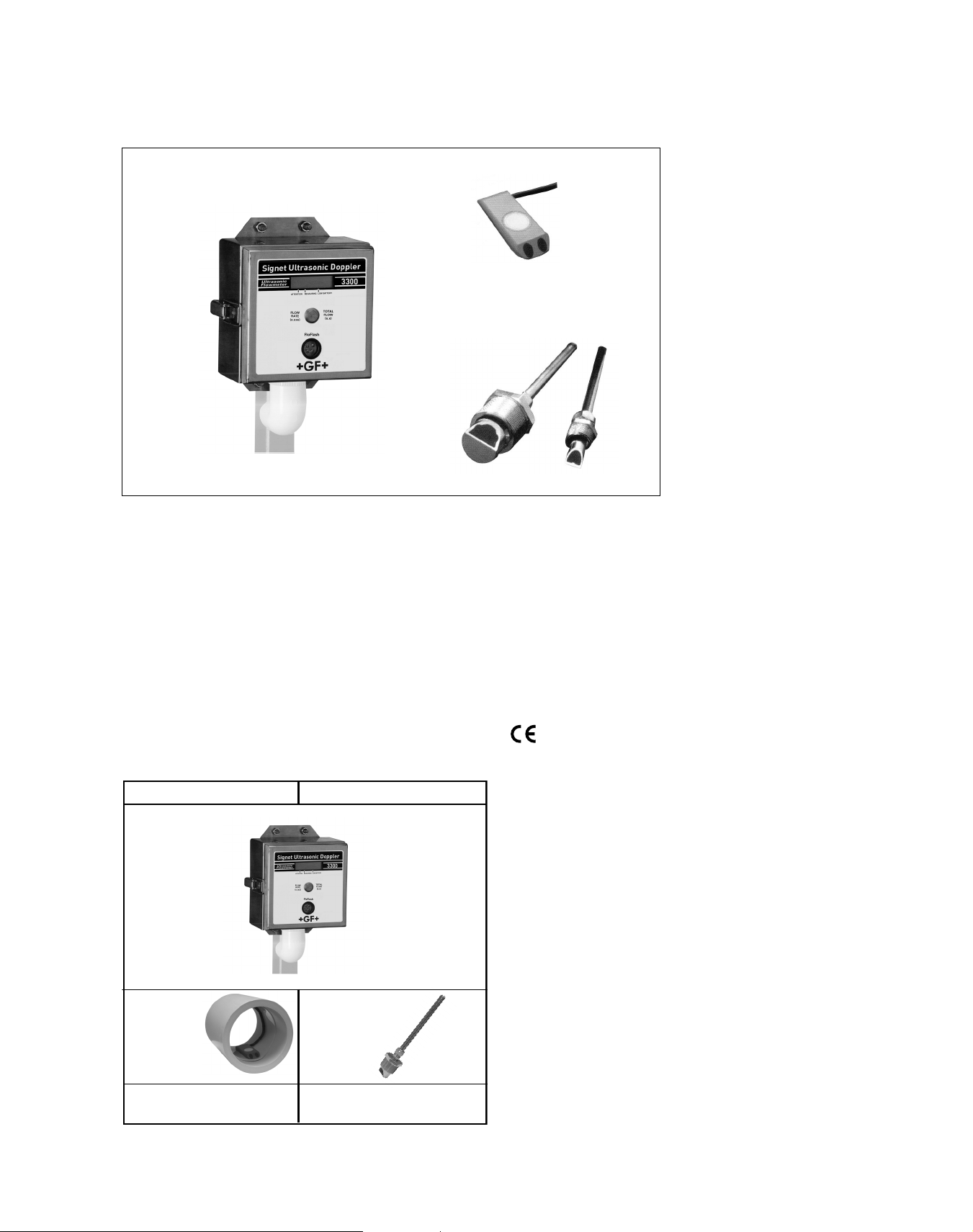
Signet 3300/3500 Ultrasonic Flow Monitor System
Features
3-3500.31X-X
• Bi-directional flow
• Measures debris
laden flow
• Open channel or full
pipe measurements
• Self-diagnostics
3-3300 (-1)
Description
The Signet 3300 Ultrasonic Flow Monitoring System advances the use of Doppler
ultrasonic technology in flow measurement by utilising proprietary “Advanced
Spectrum” signal processing to measure
the entire flow stream. The result is reliable, power-efficient, low cost liquid flow
monitoring in open or closed channels.
The Signet 3300 includes features tailored
to meet common requirements in a variety
of applications like municipal water/
wastewater, industrial waste, etc.
3-3500.320-X
3-3500.330-X
The Signet 3300 system can be equipped
with a 4 to 20mA output for interfacing to
loggers, telemetry systems or PLC’s for
long-term monitoring or an RS232 local
connection to laptops. This vandal-resistant unit is dual password protected, one
for viewing data and one for programming. These sensors have no moving
parts and lend minimal obstruction in the
flow stream.
• Local display of flow
rate and total
• Minimal straight run
requirements
• No moving parts
• Battery powered
(optional solar panel)
• High-intensity proportional flashing rate
indicator
• Weatherproof stainless steel enclosure
• Vandal-resistant
• PC access
and downloads
• Data logger
System Overview
Strap-in Sensor Mount Insertion Sensor Mount
Signet Flow Instrument
3-3300 (-1)
Mounting Kit included
Signet Flow
Sensor
3-3500.312
3-3500.313
(Pipe sold separately)
Strap mount kit required.
See Ordering Info.
66
Signet Flow Sensor
3-3500.320
3-3500.330
Pipe fitting (customer supplied)
• 4 to 20mA output
(dependant on user
defined rate)
• Wet-Tap capability
Applications
• Industrial/Municipal
Wastewater
• Pump Station
Monitoring
• Environmental
Monitoring
• Billing Networks
• Sewer and Stormwater Flow Monitoring
• Open channels,
Flumes, and weirs
www.gfsignet.com
Page 2
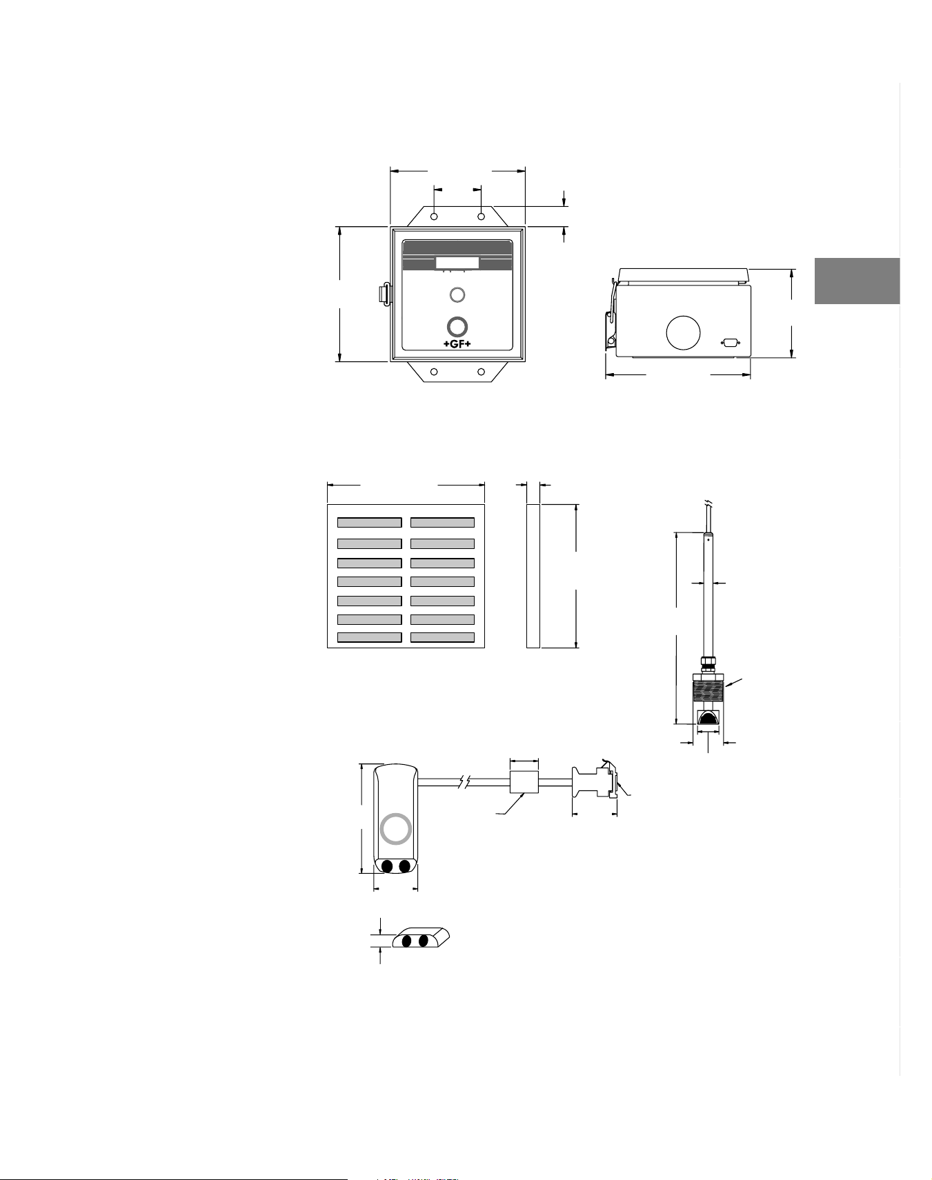
Dimensions
2
m
.
3300 Monitor Logger
Choosing
Products
200mm
(7.87 in.)
Solar Panel (optional)
270mm (10.63 in.)
200mm (7.87 in.)
30mm
(1.18 in.)
3200/
Front View
30mm (1.18 in.)
22.6mm
(0.89 in.)
245mm
(9.65 in.)
216mm (8.5 in.)
Bottom View
Insert Transducer
3500.320-X
3500.330-X
20mm
(0.78 in.)
134m
(5.28 in
Instrument
Multi-Pa-
rameter
Flow
pH/ORP
Conductivity/
Resistivity
Pressure, Level
Temperature,
Products
Other
Front View
Strap Mount Transducer
3500.31X-X
125mm
(4.92 in.)
50mm
(1.97 in.)
16mm (0.63 in.)
Top View
Clip-on
ferrite bead
Cable length:
10m or 20m
(30 ft. or 60 ft.)
Face View
13.7mm
(0.54 in.)
Side View
50mm
(1.97 in.)
(13.87 in.)
DB9 Male
Connector
352mm
45mm
(1.77 in.)
2 in. NPT
or ISO 7/1-R
73.6mm
(2.9 in.)
Installation
Wiring &
Reference
Technical
Temperature/
Pressure
Graphs
of Terms
Glossary
Reference
Part No.
www.gfsignet.com
Index
67
Page 3

Specifications
3300 Flowmeter
General
User Interface:
• Flow display is an internal 6-digit, 0.5 in.
(12mm) LCD of constant status, flow rate
and flow volume total
• High-intensity LED light flashes proportionately to flow rate (user configurable)
• RS232 serial cable for local connection to
PC, laptops and pocket PC
Flow Volume Logging Capacity:
• Configuration dependent to maximum of
250,000 records at 15 min. intervals. Includes independent logging of depth . Over
120 days data logging.
Material:
316 Stainless Steel
Electrical
Power:
• 9VDC- 1 amp, regulated power converter
required for 110 VAC/240 VAC operation.
Internal battery.
• Internal 6V 12 Ah battery , rechargeable
(charger is customer supplied) Solar panel
available*
Outputs:
•
Pulse Output: open-collector flow volume
pulse, which shorts pulse pin to system
ground
• 4 to 20 mA output
Alarm:
Short Message Service Protocol (SMS)
Program Memory:
Battery backed NVRAM
Units of Measure:
User definable for rate and total (in metric
Application Software (required)
• CD-ROM included with required FloCom™
Environmental
Enclosure Rating: IP66
Operating Temperature:
23°F to 122°F (-5°C to 50°C)
**
or English units)
for PCs with help files, user manual, installation instructions, system configuration,
data downloading & velocity profile testing.
Minimum PC requirements - Windows
98 or newer, 10MB hard drive disk space,
one serial comms port (must be COM1 or
COM2), at least 640 x 480 resolution std.
VGA screen
(1.4401) enclosure
®
3500 Series Sensors
General
Velocity Performance - all sensors
• Velocity Measurement Method:
Wetted Doppler
• Bi-directional flow display (fully accountable), reverse flow indication and net flow
calculation
• Velocity Range (strap mount and insertion
type sensors):
0.03m/s to 4m/s (0.1 ft/sec to 13 ft/sec)
• Velocity Accuracy:
±1% of value up to 3.0m/sec (9.8 ft/sec)
±1.5% of value at velocities greater than
3.0m/sec (9.8 ft/sec)
• Repeatability: 0.5% @ 1m/s (3.2 ft/s)
• Velocity Resolution:
1mm (0.04 in.) @ 1m/sec (3.3 ft/sec)
• Max. operating temp./pressure:
10 bar @ 25°C (147 psi @ 77°F)
Depth Measurement Performance
(3-3500.312, 3-3500.313)
Depth Sensor Ranges:
• 4m (13.1 ft.)
• 10m (32.8 ft.)
• Max. depth (over range): 60m (197 ft.)
without damage
Depth Sensor Accuracy:
0.2% of full scale at constant temperature in
a static stream (depth measurement only).
1% of full scale over a flow stream (5°C to
55°C)
Repeatability: 0.5% at 1m/s (3.2 ft/s)
Depth Sensor Resolution: 1mm (0.04 in.)
• Max. operating temp./pressure:
10 bar @ 25°C (147 psi @ 77°F)
Mounting
• Installation Distance:
6x diameter and 2x diameter (reversible up or down stream)
• Insertion sensor fitting: 2 in. NPT threads
or ISO 7/1-R2 threads
• Insertion Installation Limits:
DN100 to DN1800 (4 in. to 72 in.)
Wetted Materials
• Strap Mount: Epoxy and PVC
• Pressure transducer: Alumina ceramic
• Insertion Mount: Epoxy and nickel plated
brass or 316 stainless steel
• Cable: PVC 9 mm diameter from 10m
(33 ft.) to 50m (165 ft.)
Shipping Weight (Flowmeter and Sensor):
9 kg (21 lbs.)
Standards and Approvals:
• CE
* Optional battery-solar
panel for trickle charge
stand-alone power system.
Approximate life expectancy is 7 years, depending
on application conditions.
* * One pulse/volume unit
independent of integration
time period.
68
www.gfsignet.com
Page 4

Ordering Information
Electronics Package (required) - Used with any of the sensors listed below
3-3300
3-3300-1
Sensor Part Number (required) - Choose one
3-3500 Ultrasonic Doppler Flow Sensor - must be used with 3-3300 Electronics package - Choose one
3-3500 .312 -2 Example Part Number
Sensor Strap Styles - Choose one (required)
3-3500.390 Adjustable strap poly - 300mm to 450mm pipe
3-3500.392
3-3500.393 Adjustable strap poly - 225mm to 300mm pipe
Mfr. Part No. Code
Electronics
3-3300 159 000 989
3-3300-1 159 001 499
Sensors
3-3500.312-1 159 000 994
3-3500.312-2 159 000 995
3-3500.313-1 159 000 996
3-3500.313-2 159 000 997
3-3500.320-1 159 000 998
3-3500.320-2 159 000 999
Ultrasonic Doppler flow meter electronics package; includes electronics, mounting
hardware, battery, communication serial cable, set-up CD and software
Ultrasonic Doppler flow meter electronics package; includes electronics, mounting
hardware, battery, communication serial cable, set-up CD and software, with one 4 to 20mA
output.
.312 Strap-in sensor, 0 - 4 m (0 - 13.1 ft) depth measurement above transducer face
.313 Strap-in sensor, 0 - 10 m (0 - 32.8 ft) depth measurement above transducer face
Cable length for strap-in sensor
-1 10m (33 ft) cable
-2 20m (66 ft) cable
.320 Insertion sensor, nickel plated brass
.330 Insertion sensor, 316 stainless steel (1.4401)
Cable length and thread size for insertion sensor - choose one
-1 10 m (33 ft.) cable for both styles; 2 inch NPT threads
-2 20 m (66 ft.) cable for both styles; 2 inch NPT threads
-3 10 m (33 ft.) cable for both styles; ISO 7/1 R-2 threads
-4 20 m (66 ft.) cable for both styles; ISO 7/1 R-2 threads
Strap-in sensor mounting plate - polypropylene; used for pipes > 450mm
Mfr. Part No. Code
Sensors
3-3500.320-3 159 001 001
3-3500.320-4 159 001 002
3-3500.330-1 159 001 003
3-3500.330-2 159 001 004
3-3500.330-3 159 001 005
3-3500.330-4 159 001 006
Sensor Straps*
3-3500.390 159 000 986
3-3500.392 159 000 984
3-3500.393 159 000 987
Accessories and Replacement Parts
Mfr. Part No. Code Description
3-3200.075 159 000 973
(Panasonic LC-R0612P)
3-3200.076 159 000 975 Solar panel - Solarex 6V 5W MSX5V6
3-3200.395 159 000 976 Solar panel mounting kit
3-3200.090 159 000 977 Signet FloCom™ CD Doppler operating
3-3200.391
159 000 979
Battery - sealed lead acid 6V 12 Ah
system and instructions (Win32)
Communication cable 3300 to PC - DB9
serial cable
Model 3300/3500
Ordering Notes:
1) Select a Doppler Flow
meter with or without a 4
to 20mA output
2) Select a sensor: strap-in
or insertion
*Select strap: mounting
3)
plate or adjustable strap
4) Optional 30 m (100 ft.)
and 50 m (165 ft.) cable
lengths available. Call
factory for details.
5) All strap-in sensors
measure depth and
velocity, and are the
perfect choice for open
channels.
6) Insertion sensors do not
measure depth. They are
for full pipe applications
only.
7) Select a 4 to 20mA output
for interfacing to loggers,
telemetry, or PLCs.
8) For 110VAC/240VAC operation, a power supply to
9VDC/1 amp is required
(customer supplied). It
will trickle charge the
internal battery. In the
event of a power failure,
the battery will ensure
continuous data logging.
9) Minimum pipe size for installation of strap-in and
insertion sensors is DN
100 (4 in.). Maximum pipe
size for insertion sensors
is DN 1800 (72 in.)
Choosing
Products
Instrument
Multi-Pa-
rameter
Flow
pH/ORP
Conductivity/
Resistivity
Pressure, Level
Temperature,
Products
Other
Installation
Wiring &
Reference
Technical
Temperature/
Pressure
Graphs
of Terms
Glossary
www.gfsignet.com
Reference
Part No.
* All hardware is included.
Index
69
 Loading...