

Page 1
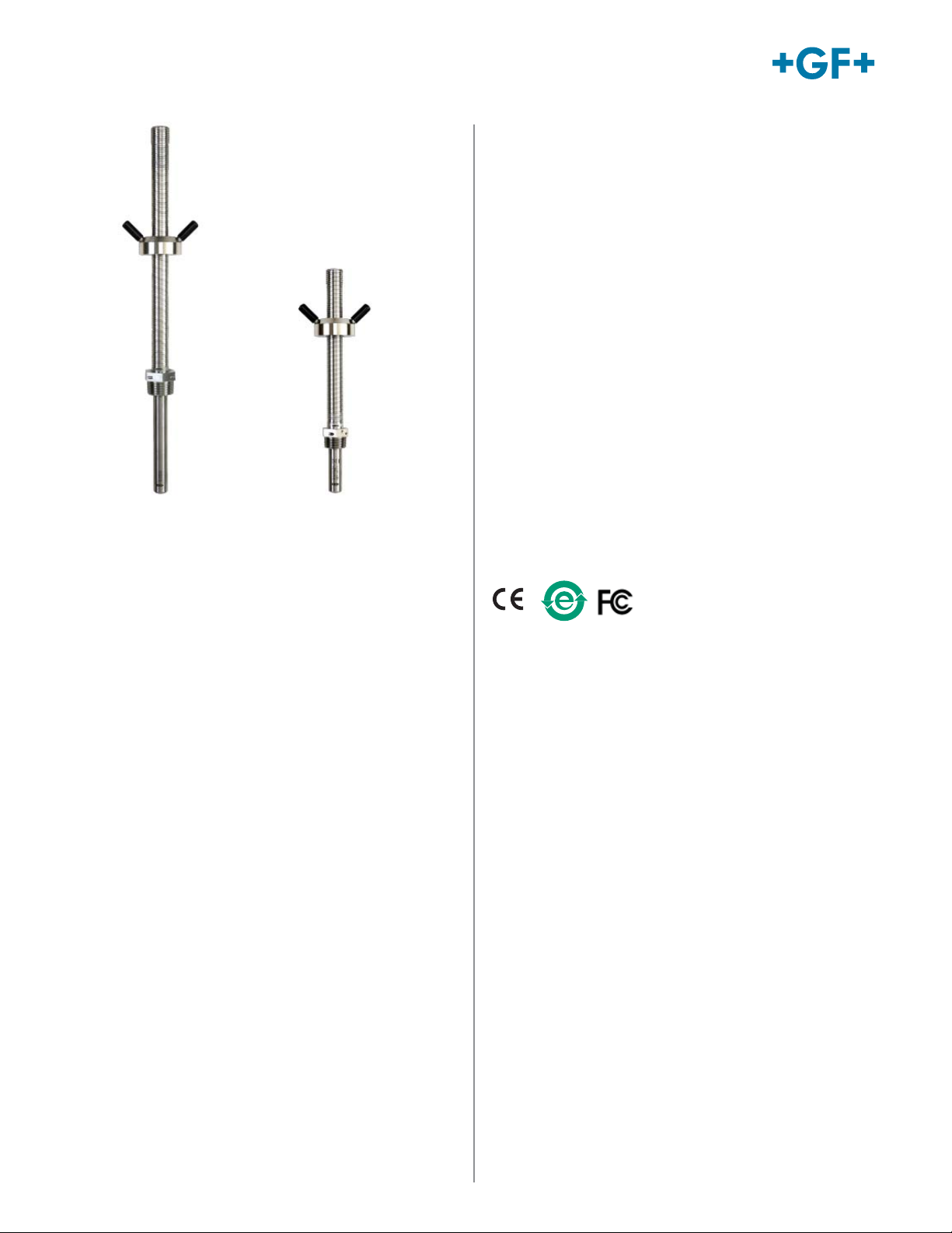
Signet 2552 Metal Magmeter Flow Sensors
Features
• NIST test certifi cate included
• Award winning hot-tap magnetic fl ow sensor up to
DN2550 (102 in.)
• Patented Magmeter technology*
• Operating range 0.05 to 10 m/s (0.15 to 33 ft/s)
• Reliable operation in harsh environments
• Repeatable: ±0.5% of reading @ 25 °C
• Three output options: 4 to 20 mA, Frequency/
Digital (S3L)
The Signet 2552 Metal Magmeter from Georg Fischer
features all-stainless steel construction. The PVDF
nosepiece and FPM O-rings are the only other wetted
materials. The 2552 installs quickly into standard
1¼ in. or 1½ in. pipe outlets, and is adjustable to fi t pipes
from DN50 to DN2550 (2 to 102 inches). Two sensor
lengths allow maximum fl exibility to accommodate a
variety of hardware confi gurations, including ball valves
for hot-tap installations.
When equipped with the frequency output, the 2552 is
compatible with any externally powered Signet fl ow
instrument, while the digital (S3L) output enables
multi-channel compatibility with Signet 8900 or 9900
Multi-Parameter instruments. Select the blind 4 to 20
mA current output to interface directly with data loggers,
PLCs or telemetry systems. Key features include Empty
Pipe Detection, LED-assisted troubleshooting, and
bi-directional span capability (in 4 to 20 mA models).
The Signet 3-0252 Confi guration Tool is available to
customize every performance feature in the 2552 so it
can be adapted to the user’s application requirements.
• ISO or NPT Threads
Applications
• Municipal Water Distribution
• Process and Coolant Flow
• Chemical Processing
• Wastewater
• Mining Applications
• Water Process Flow
• HVAC
* U.S. Patent No: 7,055,396 B1
www.gfsignet.com
Page 2
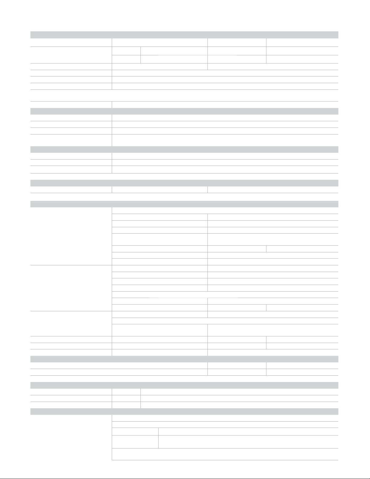
Specifi cations
General
Operating Range Minimum 0.05 m/s 0.15 ft/s
Maximum pipes to DN1200 (48 in.) 10 m/s 33 ft/s
pipes over DN1200 (48 in.) 3 m/s 10 ft/s
Pipe Size Range DN50 to DN2550 2 in. to 102 in.
Linearity ± 1% reading plus 0.1% of full scale
Repeatability ±0.5% of reading @ 25 °C
Accuracy ±2% of measured value*
*In reference conditions where the fl uid is water at ambient temperature, the sensor is inserted at the correct depth and
there is a fully developed fl ow profi le which is in compliance with ISO 7145-1982 (BS 1042 section 2.2)
Minimum Conductivity 20 μs/cm
Wetted Materials
Body and Electrodes 316L stainless steel
Insulator PVDF
O-rings FPM
Cable 4-cond + shield, PVC jacket (Fixed cable models) or Water-resistant rubber cable
assembly with Turck
Power Requirements
4 to 20 mA 24 VDC ±10%, regulated, 22.1 mA maximum
Frequency 5 to 24 VDC ±10%, regulated, 15 mA maximum
3
Digital (S
L) 5 to 6.5 VDC 15 mA maximum
Reverse Polarity and Short Circuit Protected
Cable Options
Fixed cable 7.6 m 25 ft
®
Detachable water tight sensor cable with Turck
connector (sold separately) two lengths: 4 m (13 ft) or 6 m (19.5 ft)
Electrical
Current Output
(4 to 20 mA)
Programmable and Reversible
Loop Accuracy 32 μA max. error (@ 25 °C @ 24 VDC)
Temperature Drift ±1 μA per °C max.
Power Supply Rejection ±1 μA per V
Isolation Low voltage < 48 VAC/DC from electrodes and
Maximum Cable 300 m 1000 ft
Max. Loop Resistance 300 Ω
Error Condition 22.1 mA
Frequency Output Compatible with Signet 8550, 8900, 9900 and 9900-1BC
Max. Pull-up Voltage 30 VDC
Short Circuit Protected ≤30 V @ 0 Ω pull-up for one hour
Reverse Polarity Protected to -40 V for 1 hour
Overvoltage Protected to +40 V for 1 hour
Max. Current Sink 50 mA, current limited
Maximum Cable 300 m 1,000 ft
3
Digital (S
L) Output Compatible with Signet 8900 and 9900
Serial ASCII, TTL level 9600 bps
Maximum Cable Application dependent (See 8900 or 9900 manual)
Operating Temp. Ambient (non-icing conditions) -15 °C to 70 °C 5 °F to 158 °F
Media -15 °C to 85 °C 5 °F to 185 °F
Max. Operating Pressure 20.7 bar @ 25 °C 300 psi @ 77 °F
Hot-Tap Installation Requirements
Maximum Installation Pressure 20.7 bar 300 psi
Maximum Installation Temp (Insertion/Removal) 40 °C 104 °F
Do not use hot-tap installation where temperatures will exceed 40 °C or if hazardous liquids are present.
Shipping Weights
3-2552-2X-A-11/A-12 2.50 kg 5.51 lb
3-2552-2X-B-11/B-12 2.30 kg 5.07 lb
3-2552-3X-A-11/B-11/A-12/B-12 4.00 kg 8.81 lb
Standards and Approvals
CE, FCC
RoHS compliant, China RoHS
NEMA 4 (IP65) Fixed cable models
NEMA 6P (IP68) Submersible cable models only. Signet recommends maximum 3 m
Manufactured under ISO 9001 for Quality and ISO 14001 for Environmental Management
and OHSAS 18001 for Occupational Health and Safety
®
NEMA 6P connector
auxiliary power
in non-icing conditions
10 ft) submersion depth for maximum 10 days continuous submersion.
www.gfsignet.com
Page 3
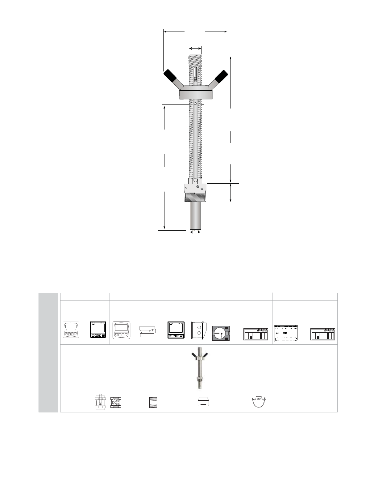
Dimensions
2552-2 models
276.3 mm
(10.88 in.)
2552-3 models
419 mm
(16.5 in.)
137 mm
(5.4 in.)
Acme threads
32 mm
(1.25 in.)
2552-2 models
290 mm
(11.4 in.)
2552-3 models
432 mm
(17.0 in.)
41 mm
(1.6 in.)
Panel Mount
Signet Instruments
8550 9900
8900 9900-1BC
OR
ENTER
Signet 2552 Magmeter
(Standard or Hot-Tap)
System Overview
ball or gate valve
1¼” or 1½”
In-Line Installation
Pipe, Tank, Wall Mount
Signet Instruments
8550 with 3-8050 Universal Mount Kit
9900-1P 9900-1BC with Rear Enclosure
+
nipple
1¼” or 1½”
OR
Weld-on weldolet
1¼” or 1½” outlet
25.4 mm
(1.0 in.)
+
4 to 20 Output
Customer Supplied Chart Recorder,
Programmable Logic Controller, or
Programmable Automation Controller
PLC
OR
Iron strap-on saddle
1¼” or 1½” outlet
Automation System
0486 Profibus Concentrator
and Customer Supplied
Programmable Logic Controller or
Programmable Automation Controller
L IN+
L IN-
N/C
L OUT+
L OUT-
N/C
L IN+
L IN-
+5V OUT
DATA
GND
L IN+
L IN-
+5V OUT
DATA
GND
Out
In
S3L Loop
S3L Loop
USB
Profibus
Channel 5
Channel 6Channel 7
Valve
Signet 3-0486 Profibus Concentrator
Address
Power
Channel 1
Channel 2
Channel 3
Channel 4
24 VDC
0.40A Max
S3LFreq
S3LFreq
S3LFreq
S3LFreq
+5V OUT
+5V OUT
+5V OUT
+5V OUT
Freq IN
Freq IN
Freq IN
PWR+
PWR+
PWR+
PWR-
PWR-
PWR-
DATA
DATA
DATA
GND
GND
GND
PLC
+
Freq IN
DATA
GND
All sold separately
Page 4
Sensor Selection Guide
The 2552 Magmeter can be installed into a variety of pipe sizes. Follow the steps below to ensure that you choose
the right sensor for your application.
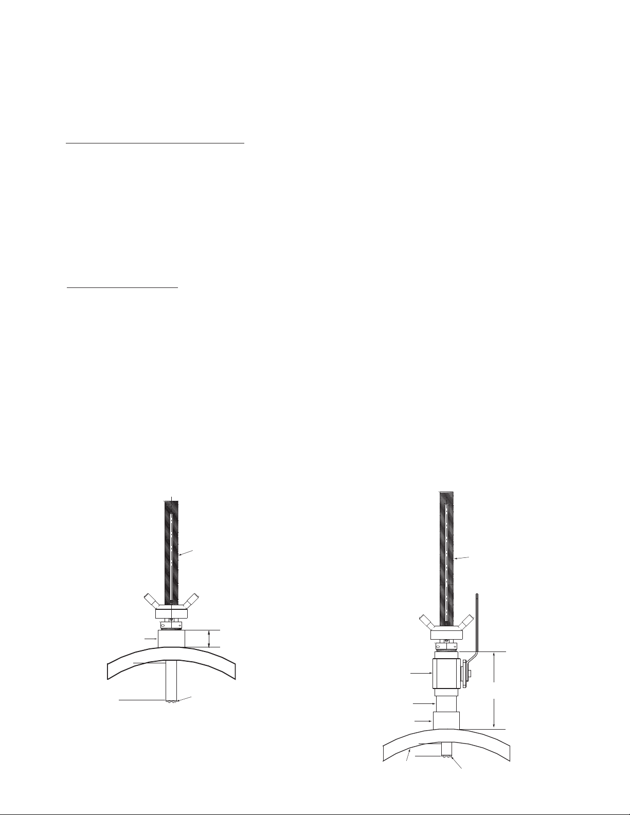
Step 1: Determine how the sensor will be installed
A. For standard (non Hot-Tap) installations:
The height of the weldolet (threadolet) and pipe adapter(s) should be determined before the sensor is purchased.
• For retrofi t installations, the stack height, or “A”
dimension (see Fig. 1), is the overall height from
the top of the pipe to the highest point of the stack.
• Sensor tip must be positioned at 10% of pipe ID
• For new installations, Signet recommends a
weldolet (threadolet) and an adapter to
accommodate the 1¼ in. (or 1½ in. for 2552-3)
sensor process threads. The stack height, or “A”
dimension (see Fig. 1), is the overall height from
the top of the pipe to the highest point of the stack
before the sensor is connected
B. For Hot-Tap installations:
The stack height of the ball valve, nipple weldolet (threadolet) and pipe adapters should be determined before the
sensor is purchased.
• For retrofi t installations, the ball valve must be at
least a 1¼ in. (or 1½ in. for 2552-3) valve. The
stack height, or “A” dimension (see Fig. 2), is the
overall height from the top of the pipe to the top of
the ball valve.
• Sensor tip base must be positioned at 10% of
• For new installations, Signet recommends a 1¼ in.
or 1½ in. full port ball valve, a short nipple and a
weldolet (threadolet). The stack height or “A”
dimension (see Fig. 2) is the overall height from the
top of the pipe to the top of the ball valve before the
sensor is connected.
pipe ID
Fig. 1
Standard installation with “A” dimension using a
weldolet (threadolet)
Fig. 2
Hot-Tap installation with “A” dimension using a ball valve, short
nipple and weldolet (threadolet)
Weldolet
or Saddle
10% of pipe ID
Sensor
Housing
Sensor
“A”
Dimension
Ball
Valv e
Nipple
Weldolet
Pipe
Wall
10% of
pipe ID
Sensor
Housing
Sensor
“A”
Dimension
Page 5
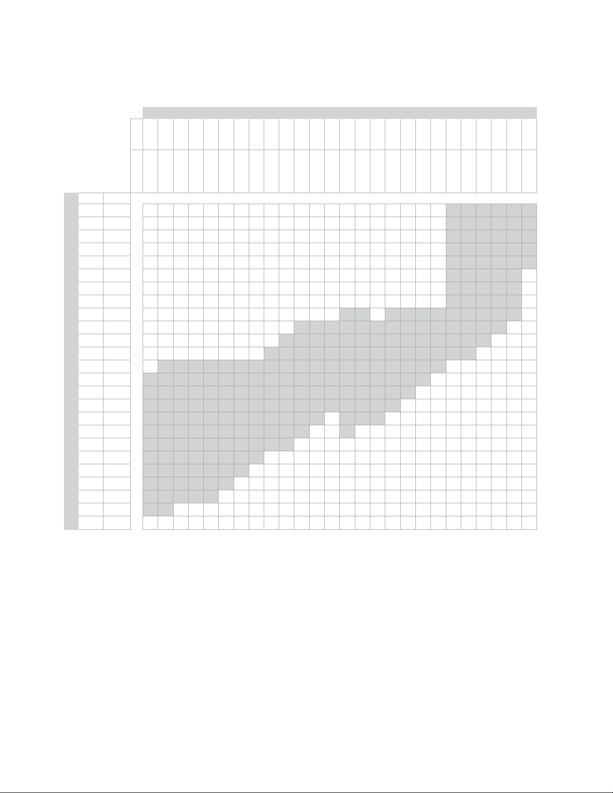
Step 2: Determine how the sensor will be installed
Once the “A” dimension is determined, go to the sensor selection table and fi nd your “A” dimension on the left column.
Next, fi nd the appropriate pipe size at the top of the chart. To determine the correct sensor size locate where the pipe
size column meets the max “A” dimension row.
Pipe Size
inches22.5
DN5065
mm inches
50.8 2 22222222222222222222333333
63.5 2.5 22222222222222222222333333
76.2 3 22222222222222222222333333
88.9 3.5 22222222222222222222333333
101.6 4 22222222222222222222333333
114.3 4.5 2222222222222222222233333
127 5 2222222222222222222233333
139.7 5.5 2222222222222222222233333
152.4 6 2222222222222332333333333
165.1 6.5 222222222233333333333333
177.8 7 22222222233333333333333
190.5 7.5 2222222233333333333333
228.6 9 23333333333333333333
Max. "A" Dim
241.3 9.5 3333333333333333333
254 10 333333333333333333
266.7 10.5 33333333333333333
279.4 11 333333333333 333
292.1 11.5 33333333333 3
304.8 12 3333333333
317.5 12.5 33333333
330.2 13 3333333
342.9 13.5 333333
355.6 14 33333
375.9 14.8 33
381 15
3 to 3 ½45
80 to 90
100
6 to 81012 to 141618
125
150 to 200
250
300 to 350
400
450
20
500
22
550
24
600
26 to 28
30 to 323436 to 38
650 to 700
750 to 800
850
40 to 424854
900 to 950
1000 to 1100
1200
1400
60
1500
66
1700
72
1800
78
2000
84
2100
102
2.58 m
Legend:
2: Use 3-2552-2, max. insertion = 236 mm (9.3 in.)
3: Use 3-2552-3, max. insertion = 368 mm (14.8 in)
This chart is based on the thickest commonly available pipe.
Step 3: Refer to Ordering Information to select corresponding part numbers
Ordering Notes
1) Sensor insertion depth is the distance from the
bottom of the sensor housing to the tip of the
sensor.
2) Hot-Tap installations require a 1¼ in. or 1½ in.
ball valve.
Application Tips
• Minimum process liquid conductivity requirement
is 20 μS/cm.
• 1½ x 1¼ inch and 2 x 1¼ inch (2552-2 only)
retrofi t adapters are available for replacement
installations of Signet 2552 and 2540 sensors.
3) See Sensor Selection Guide on previous page to
determine the sensor length required.
www.gfsignet.com
Page 6
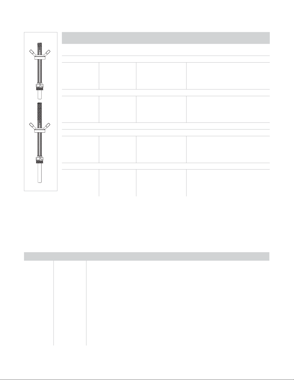
Ordering Information
Mfr. Part No. Code
Frequency or Digital (S
3
L) output
Sensor
Insertion Depth
Process Connection Thread Options
for use with any Signet Flow or Multi-Parameter Instruments
Fixed cable, 7.6 m (25 ft); no connector
3-2552-21-A-11 159 001 513 9.3 inches* 1¼ inch NPT**
3-2552-22-A-11 159 001 517 9.3 inches* 1¼ inch ISO**
3-2552-33-A-11 159 001 521 14.8 inches* 1½ inch NPT**
3-2552-34-A-11 159 001 522 14.8 inches* 1½ inch ISO**
Watertight sensor connector; cable sold separately
3-2552-21-B-11 159 001 515 9.3 inches* 1¼ inch NPT**
3-2552-22-B-11 159 001 519 9.3 inches* 1¼ inch ISO**
3-2552-33-B-11 159 001 523 14.8 inches* 1½ inch NPT**
3-2552-34-B-11 159 001 524 14.8 inches* 1½ inch ISO**
4 to 20 mA output
Fixed cable, 7.6 m (25 ft); no connector
3-2552-21-A-12 159 001 514 9.3 inches* 1¼ inch NPT**
3-2552-22-A-12 159 001 518 9.3 inches* 1¼ inch ISO**
3-2552-33-A-12 159 001 525 14.8 inches* 1½ inch NPT**
3-2552-34-A-12 159 001 526 14.8 inches* 1½ inch ISO**
Watertight sensor connector; cable sold separately
3-2552-21-B-12 159 001 516 9.3 inches* 1¼ inch NPT**
3-2552-22-B-12 159 001 520 9.3 inches* 1¼ inch ISO**
3-2552-33-B-12 159 001 527 14.8 inches* 1½ inch NPT**
3-2552-34-B-12 159 001 528 14.8 inches* 1½ inch ISO**
* Customer must determine stack height (ball valve, nipple, weldolet, etc.). Refer to Sensor Selection on previous
page to determine “A” dimension. Sensor tip must be positioned at 10% of pipe ID.
** 1¼ inch process connection is the standard thread size on the 3-2552-2X-X-XX: For the 2552-3 the 1½ inch
process connection is standard and the 1¼ inch is available as a special order.
Accessories and Replacement Parts
Mfr. Part No. Code Description
2120-1512 159 001 425 1½ x 1¼ inch NPT adapter for retrofi tting 2540 installation to 2552 - 316 SS
2120-2012 159 001 426 2 x 1¼ inch NPT adapter for retrofi tting 2550 installation to 2552 - 316 SS
3-2552.392 159 001 530 1¼ inch NPT full port stainless steel ball valve and nipple kit
3-2552.393 159 001 531 1¼ inch NPT full port brass ball valve & nipple kit
3-2552.394 159 001 532 1½ inch NPT conduit adapter, aluminum for -1 and -2 units
4301-2125 159 001 533 1¼ inch NPT full port ball valve - brass
4301-3125 159 001 387 1¼ inch NPT full port ball valve - stainless steel
5541-4184 159 001 388 4-conductor cable assembly with water-tight connector, 4 m (13 ft)
5541-4186 159 001 389 4-conductor cable assembly with water-tight connector, 6 m (19.5 ft)
special order special order 4-conductor cable assembly with water-tight connector, cable length in 25 ft increments
special order special order 1¼ in. NPT or ISO process connection threads to replace 1½ in. NPT or ISO threads
3-0252 159 001 808 Confi guration Tool
3-2552.099 Rev F (02/16)
© Georg Fischer Signet LLC
3401 Aero Jet Avenue, El Monte, CA 91731-2882 U.S.A. • Tel. (626) 571-2770 • Fax (626) 573-2057 • www.gfsignet.com • e-mail: signet.ps@georgfi scher.com
Specifi cations subject to change without notice. All rights reserved. All corporate names and trademarks stated herein are the property of their respective companies.
www.gfsignet.com
 Loading...