

Page 1
Signet 0252 Conguration Tool
*3-0252.090*
3-0252.090 Rev. A 01/16
Description
The 0252 Conguration Tool is a USB to Digital (S3L) convertor and Microsoft®
Windows® compatible software program used for interfacing with Signet 9900
Transmitters and blind sensors via a computer.
The 0252 tool and software allows:
• Set application parameters (Engineering units, 4 to 20 mA span, etc.)
• Save the setting conguration data to a computer le.
• Upload a previously stored conguration data le into the Signet product.
• Monitor a sensor's performance and log the data to a le.
• Reset the product settings to factory default condition.
Certain parameters (such as calibration) cannot be changed because access
to an external sensor is required.
English
Operating Instructions
• English
• Deutsch
• Français
• Español
Table of Contents
Warranty Statement ................................................................................ 2
Product Registration ............................................................................... 2
Safety Information ................................................................................... 2
Specications .......................................................................................... 2
Required Equipment ............................................................................... 3
Install Software ....................................................................................... 3
Run Software .......................................................................................... 3
Set Software Language .......................................................................... 3
Sensor Wiring (2250, 2350, 2450, 2750) ................................................ 4
2551 Magmeter Wiring............................................................................ 5
2552 Magmeter Wiring............................................................................ 5
9900 Wiring ............................................................................................. 6
General Software Operation ................................................................... 6
Sensor Operation .................................................................................... 7
2551 & 2552 Operation ........................................................................ 8-9
9900 Operation ................................................................................ 10-11
Datalogger Operation............................................................................ 12
Ordering Information ............................................................................. 12
Microsoft, Windows, and Windows Vista are registered trademarks of
Microsoft Corporation in the United States and other countries.
Page 2
Warranty Information
Specications
Refer to your local Georg Fischer Sales ofce for the
most current warranty statement.
All warranty and non-warranty repairs being returned
must include a fully completed Service Form and
goods must be returned to your local GF Sales ofce
or distributor.
Product returned without a Service Form may not be
warranty replaced or repaired.
Signet products with limited shelf-life (e.g. pH, ORP,
chlorine electrodes, calibration solutions; e.g. pH
buffers, turbidity standards or other solutions) are
warranted out of box but not warranted against any
damage, due to process or application failures (e.g.
high temperature,
mishandling (e.g. broken glass,
chemical poisoning, dry-out) or
damaged membrane,
freezing and/or extreme temperatures).
Product Registration
Thank you for purchasing the Signet line of
Georg Fischer measurement products.
If you would like to register your product(s), you can
now register online in one of the following ways:
• Visit our website www.gfsignet.com.
Under Service and Support click on
Product Registration Form
• If this is a pdf manual (digital copy), click here
Safety Information
Caution / Warning / Danger
Indicates a potential hazard.
Failure to follow all warnings may lead to
equipment damage, injury, or death
Electrostatic Discharge (ESD) /
Electrocution Danger
Alerts user to risk of potential damage to product
by ESD,
death via electrocution.
and/or risk of potential of injury or
Compatibility
Signet Products ................... 2250, 2350, 2450, 2750, 2551,
2552, and 9900 Transmitter
Operating System ................ Windows XP, Windows Vista,
Windows 7 (32 and 64 bit),
Windows 8, 8.1 (32 and 64 bit)
Windows 10 (32 and 64 bit)
General
Enclosure............................. ABS
Red Indicator ....................... POWER ON
Blue Indicator....................... DATA COMMUNICATION
Input connections ................ 3-terminal connectors,
max. 14 AWG
Electrical
Communication rate ............ Maximum 19.2 kbs
Input power .......................... Supplied by USB interface
Output power ....................... 5 VDC ± 5%
Power consumption ............. 5 V @ 15 mA
Maximum current source ..... 50 mA
Maximum cable ................... 300 m (1000 ft)
Environmental
Storage Temperature ........... -20 °C to 100 °C
(-4 °F to 212 °F)
Relative Humidity................. 0 to 90% non-condensing
Operating Temperature ........ -15 °C to 55 °C
(5 °F to 131 °F) (module only)
Shipping Weight ................ 0.22 kg (0.48 lb)
Standards and Approvals
CE, RoHS Compliant
China RoHS
This device complies with Part 15 of the FCC rules.
Operation is subject to the following two conditions:
(1) This device may not cause harmful interference, and,
(2) This device must accept any interference received,
including interference that may cause undesired
operation.
Note / Technical Notes
Highlights additional information or detailed
procedure.
2
Signet 0252 Conguration Tool
Page 3
Required Equipment
Equipment:
• 3-0252 Tool: one USB to Digital (S3L) converter
• 1 m (3 ft) 9900 programming cable with terminal plug
• USB to USB extension cable
• Software installation CD
• PC / laptop with free USB port
• 24 VDC Isolated power source (Required to program
4 to 20 mA sensors, 2551 and 2552 only)
Install Software
Caution
Managed systems and network systems may
have security measures enabled that block the
installation of this program.
See the network administrator or IT (Information
Technology) staff if the software cannot be installed.
Application specic information:
2250, 2350, 2450, 2750:
• Engineering Units, 4 to 20 mA span
2551 & 2552:
• Engineering Units, K-Factor, Pipe ID, Timebase,
Averaging, Sensitivity, Noise Rejection,
Low Flow Cut-Off, 4 to 20 mA span
9900:
• Instrument Type (Flow, pH, ORP, Cond/Resist,
Pressure, Level, Temperature, 4 to 20 mA, Salinity)
• Sensor type specic settings
1. Insert the CD ROM into the computer's CD/DVD drive.
• If Autorun is enabled on the computer, the
installation wizard will start.
• If Autorun is disabled on the computer, use Windows
Explorer to browse the contents of the CD and
double-click on the setup.exe le.
2. Follow the prompts in the installation wizard to
complete installing the software.
Run Software
1. On the PC, click Start and select Program Files.
2. Click on the Georg Fischer Signet LLC folder.
3. Click on the 0252 folder.
4. Click on the 0252 Tool icon.
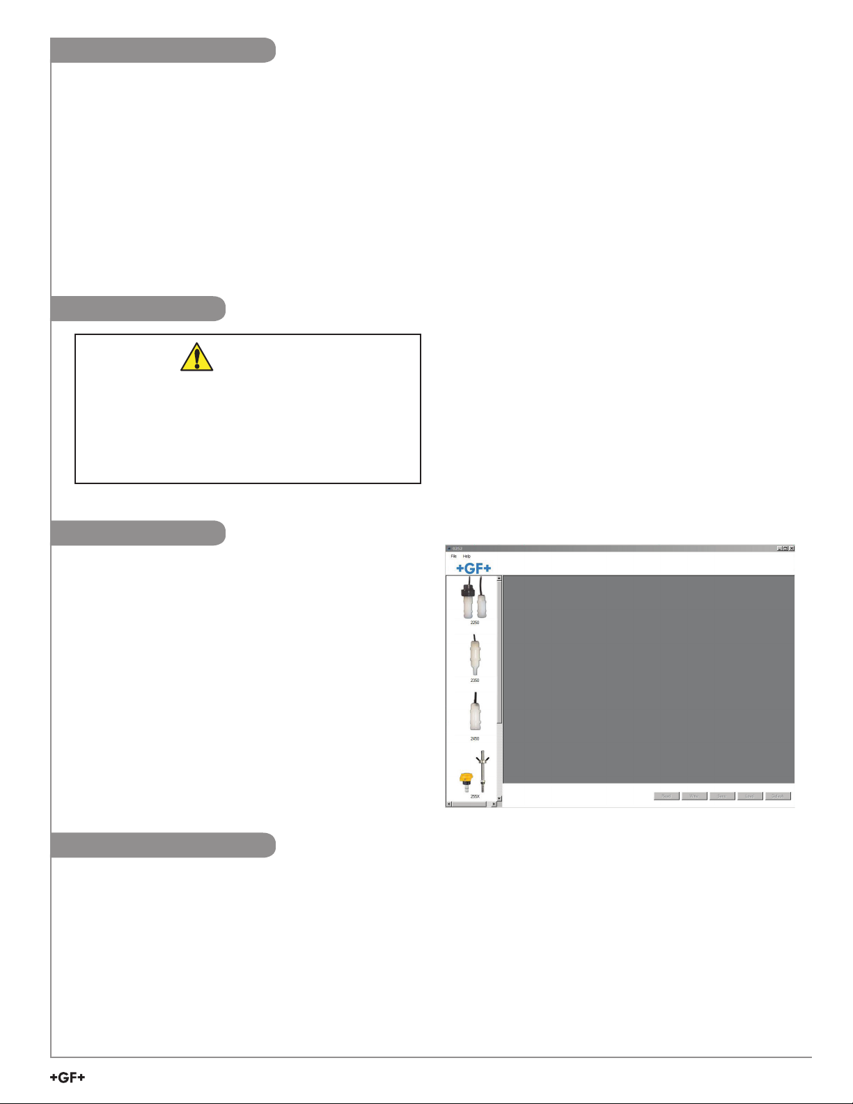
5. The 0252 software screen shown here should be
on the computer display.
NOTE: Each time the 0252 software is launched, it
automatically checks for and applies updates.
Software version is displayed by clicking on the
Help menu, then clicking on About.
Set Software Language
The 0252 software saves your language preferences. Each time the software is launched, the previous language
selection will be used. English is the default language.
1. Click on the File menu in the upper left.
2. Click on Preferences.
3. A separate Preferences dialog box should be on the computer display.
4. Select the desired language from the drop-down menu.
Supported languages: English, French, German, Spanish, Italian, Portuguese, Chinese
5. Click Save to set language preference.
Signet 0252 Conguration Tool
3
Page 4
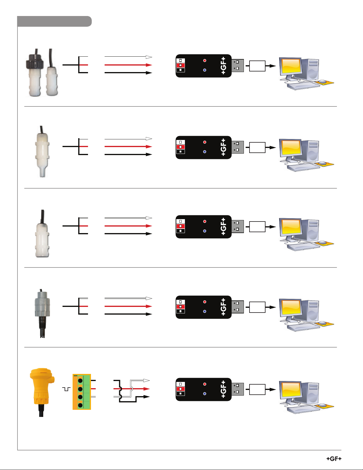
Sensor Wiring
White
Red
Black
USB
GND
Data
+5V out
Windows PC
Signet 2250 Hydrostatic Level Sensor
White
Red
Black
Signet 2350 Temperature Sensor
White
Red
Black
Signet 2450 Pressure Sensor
White
Red
Black
GND
Data
+5V out
GND
Data
+5V out
GND
Data
+5V out
USB
Windows PC
USB
Windows PC
USB
Signet 2750 Submersible pH Sensor
White
Red
Black
Signet 2750 In-Line pH/ORP Sensor
+
-
S
4
3
2
1
Black
Red
White
GND
Data
+5V out
GND
Data
+5V out
Windows PC
USB
Windows PC
USB
Windows PC
4
Signet 0252 Con guration Tool
Page 5

2551 Magmeter Wiring
JP2
FREQUENCY OUT
DIGITAL (S L) OUT
3
Freq/Digital jumper
must be in Digital position
USB
GND
Data
+5V out
Windows PC
White
Red
Black
1
2
3
4
USB
GND
Data
+5V out
Windows PC
Brown
Black
White
Blue
Frequency or Digital (S3L) Output
4
3
White
2
Red
1
Black
GND
Data
+5V out
USB
4 to 20 mA Output
2552 Magmeter Wiring
Frequency or Digital (S
FREQUENCY OUT
DIGITAL (S
4
3
2
1
Brown
Blue
White
Black
3
L) OUT
Black
3
L) Output
White
Red
-
+
JP2
Freq/Digital jumper
must be in Digital position
GND
Data
+5V out
Isolated
24 VDC
GND
Data
+5V out
Windows PC
USB
Windows PC
CAUTION!
Do not connect power directly to the 0252 Con guration Tool.
Improper power supply wiring can cause damage to the 0252 hardware
and computer. Turn 24 VDC Power OFF when wiring the magmeter.
USB
Windows PC
4 to 20 mA Output
Blue
White
Brown
Black
*Wire 2
*Wire 1
Blue
White
*Wire 3
*Wire 2
-
+
GND
Data
+5V out
Isolated
24 VDC
*Wire 3
To -VDC
Wire Nut
To GND
USB
CAUTION!
Windows PC
Do not connect power directly to the 0252 Con guration Tool.
Improper power supply wiring can cause damage to the 0252 hardware
and computer. Turn 24 VDC Power OFF when wiring the magmeter.
*Additional wire required
Signet 0252 Con guration Tool
5
Page 6

9900 Wiring
Disconnect power on the 9900 prior to proceeding.
If the 9900 is using the Direct Conductivity/Resistivity Module, the module will need to be removed from the 9900.
Refer to the Direct Conductivity/Resistivity Module Instruction Sheet for instructions.
1. Disconnect power on the 9900.
2. Unplug the sensor connector from the S3L/Frequency input jack on the 9900 and connect the 0252 Tool in its place.
3. Reconnect power to the 9900.
SHLD
GND
DATA
V+
White
Red
GND
Data
+5V out
USB
Windows PC
General Software Operation
On all screens Read, Write, Save, Load, and Default buttons can be found in the lower right corner.
Read Loads the data from the connected device (sensor or transmitter) and updates the software’s display.
NOTE: This will overwrite any changes made in the 0252 software since the last Write.
Write Applies the data entered in the 0252 software to the connected device. Once you have entered the desired
setting changes in the software screens, press Write to load your new settings onto the connected device.
Save Stores the entire 0252 settings con guration, as currently displayed in the application, to a speci ed location
on your computer. (You will be asked to select a le location and provide a le name)
Load Opens a previously saved settings con guration le. See Save function above.
NOTE: The le must be a 0252 settings con guration le.
The software will verify whether the user-selected le is the correct type.
Default Resets all data on all application screens to a factory default condition. A con rmation dialog box will be
presented with a warning explaining all un-saved con guration information will be erased.
After resetting the software to a factory default condition, click Write to reset the connected device to a
factory default condition.
NOTE: Performing the above reset to factory default condition will not change the input type on the
9900 Transmitter.
6
Signet 0252 Con guration Tool
Page 7

Sensor Operation
Application settings:
2250 2350 2450 2750
1 Engineering units in., ft, cm, m ˚C or ˚F psi, kpa, bar pH or (ORP)
Loop Output settings:
Min
0
-10 ˚C
(14 ˚F)
0
0 pH
(-1000 mV)
-XU:
2 4 mA Set Point
Max
276.8 in., 23.07 ft,
703.1 cm, 7.03 m
-XL:
1384.0 in, 115.33 ft,
100 ˚C
(212 ˚F)
10, 50, 250 psi
(69, 344.7,
1723.7 kpa)
(0.7, 3.5, 17.2 bar)
14 pH
(2000 mV)
3515.0 cm, 35.15 m
Min
0
-10 ˚C
(14 ˚F)
0
0 pH
(-1000 mV)
-XU:
3 20 mA Set Point
Max
276.8 in., 23.07 ft,
703.1 cm, 7.03 m
-XL:
1384.0 in, 115.33 ft,
100 ˚C
(212 ˚F)
10, 50, 250 psi
(69, 344.7,
1723.7 kpa)
(0.7, 3.5, 17.2 bar)
14 pH
(2000 mV)
3515.0 cm, 35.15 m
Write or Save settings:
4a
Click “Write” to copy these settings to the product.
or
Click “Save” to save these settings to a local computer le for later use.
4b
5 To use a saved le (from 4b):
1. Click “Load”
2. Navigate to the saved le
3. Select “Open”
4. Click “Write”
5. Click “Read” to conrm
Signet 0252 Conguration Tool
7
Page 8

2551 & 2552 Operation
Application settings:
Factory Set
2551 & 2552
1 Flow Units m m, ft, m3, L, ft3, US Gal, Imp. Gal, Acre in.
2 Time Base sec Sec, Min, Hour, Day
3 Pipe ID (Inside Diameter) 44.0 0 - 5000
4 Pipe ID Units mm mm, in.
5 K-Factor Units Pulses / Liter Pulses / Liter, Pulses / Gallon
0.000100 - 999999.1
6 K-Factor 65.76670
See Magmeter manual.
Available at www.gfsignet.com
7 Averaging (in seconds) 14
1
/
, ¼, ½, 1, 1½, 3, 7, 14, 25, 50, 100
10
8 Sensitivity (%) 25 100, 50, 30, 25, 20, 15, 10, 8, 5, 2
9 Noise Rejection (Hz) 60 50 or 60
10 Low Flow Cut Off (% of full scale) 0 0 to 20% Full Scale
Loop Output settings:
11 4 mA Set Point (Flow Units / Time Base) 0.00000
0.00000 - 999999.00000
12 20 mA Set Point (Flow Units / Time Base) 5.00000
Write or Save settings:
13a
Click “Write” to copy these settings to the product.
or
13b
Click “Save” to save these settings to a local computer le for later use.
14
To use a saved le (from 13b):
1. Click “Load”
2. Navigate to the saved le
3. Select “Open”
4. Click “Write”
5. Click “Read” to conrm
8
Signet 0252 Conguration Tool
Page 9

2551 & 2552 Operation
1
2
3
4
5
6
7
8
9
10
11 & 12
13a 13b
(General Software Operation, pg. 6)
Notes:
Set the time the Magmeter will use as the averaging period.
Averaging
Sensitivity
Noise Rejection Select 50 Hz or 60 Hz according to local AC power specications.
Low Flow Cut Off
Example: With averaging at 14 seconds, each display is an average of the previous
14 seconds input. Use higher averaging times to smooth the display and current output
where the ow in the pipe is erratic.
Set the percentage of change in the ow rate required to allow the Magmeter to override
AVERAGING and jump to a new ow rate immediately (2551 maximum range is 10 m/s).
See Magmeter manual for an explanation of Averaging and Sensitivity: www.gfsignet.com
Set the ow rate where all Magmeter outputs will be forced to zero.
When the ow rate drops below this value, the frequency output will be 0 Hz and the
current output will be 4 mA.
Signet 0252 Conguration Tool
9
Page 10

9900 Operation
Initiating Communication with the 9900:
1a Factory Congured 9900 (new or reset):
1. If the display reads "PUSH Enter SELECT SENSOR" the 9900 is ready for communication.
2. Proceed to step 2 below.
Previously congured 9900:
1b
1. Press and hold ENTER for 3 seconds. The display will change to the MENU mode.
2. Press ▲ once. The OPTION menu will flash. Press ENTER
3. The CONTRAST setting will be displayed.
Press ▲ twice (Gen II, III, IV) or press ▲ once (Gen I) to display REMOTE SETUP.
4. Press ► to edit REMOTE SETUP. If required, enter the security code.
5. Press ▲ to change the ashing NO to YES. Press ENTER to conrm change.
6. REMOTE SETUP should be ashing, indicating the 9900 is ready for communication with the 0252 Tool.
Set Instrument Type:
Select sensor type to be wired to the 9900 from the
2
drop-down menu at the top of the screen.
Flow, pH, ORP, Conductivity, Pressure, Level,
Temperature, 4 to 20 mA Input, Salinity
Application settings:
3 Select the Input, Calibration, Loop, Relay, or Option tabs to choose the desired menu for the selected sensor.
Refer to the 9900 manual for details pertaining to specic settings for each sensor type and menu item.
4
Available at www.gfsignet.com. Click Products > Multi-Parameter Instruments > 9900 Transmitter
Write or Save settings:
5a
Click “Write” to copy these settings to the product.
or
Click “Save” to save these settings to a local computer le for later use.
5b
6 To use a saved le (from 5b):
1. Click “Load”
2. Navigate to the saved le
3. Select “Open”
4. Click “Write”
5. Click “Read” to conrm
When conguration is complete:
7 Disconnect power from the 9900.
8 Disconnect the 0252 Tool from the 9900.
9 Reconnect the sensor or reinstall the Direct Conductivity/Resistivity Module.
10 Reconnect Power to the 9900.
To congure an additional 9900 Transmitter with the same settings:
11 Click "Save" to save these settings to a local computer le.
12 Wire another 9900 as shown on page 7.
13 Initiate communication with the 9900 via step 1a or 1b above.
14 Load the saved settings via step 6 above.
10
Signet 0252 Conguration Tool
Page 11

9900 Operation
2
3
5a 5b
(General Software Operation, pg. 6)
Signet 0252 Conguration Tool
11
Page 12

Datalogger Operation
The 0252 can serve as a eld data logger to download data directly into a *.csv (Comma Separated Value) le.
NOTE: The 0252 does NOT have internal memory to store data.
It must be connected to a computer to use the datalog function.
1. Select the sensor type and click on Read.
2. Click the Monitor tab to open the datalog setup window.
3. Enter the Logging Interval. This value represents the time between log records.
The minimum interval is 1 second, and the maximum interval is 86400 seconds (24 hours).
Example: If the Log Interval is set to 60 seconds, the 0252 will record the temperature once every minute.
4. The 0252 saves data les in *.csv format. The maximum number of records allowed for this type of le is
65535 records. If the logging interval is 60 seconds = 1092 hours of continuous recorded data.
5. Click Log and enter the le name for the 0252 to store the recorded data and click Save.
6. Click Log File check box to enable logging. If you do not wish to save the data, skip to step 7.
7. Click Graph to start monitoring the sensor.
2
3
6
Ordering Information
Mfr. Part No. Code Description
3-0252 159 001 808 0252 Conguration Tool
Replacement Parts
6682-3004 159 001 725 Replacement 9900 Terminal Block Plug
57
1
Georg Fischer Signet LLC, 3401 Aero Jet Avenue, El Monte, CA 91731-2882 U.S.A. • Tel. (626) 571-2770 • Fax (626) 573-2057
For Worldwide Sales and Service, visit our website: www.gfsignet.com • Or call (in the U.S.): (800) 854-4090
For the most up-to-date information, please refer to our website at www.gfsignet.com
3-0252.090 Rev. A 01/16 English © Georg Fischer Signet LLC 2016
 Loading...