

Page 1
Signet 2839-1V to 2842-1V PVDF Conductivity Electrodes
*3-2840.090-1*
3-2840.090-1 Rev. B 01/15
Operating Instructions
Table of Contents
English
2839: 0.01 cm-12840: 0.1 cm
2841: 1.0 cm
2842: 10.0 cm
-1
-1
-1
Warranty Information ............................................................................ 2
Product Registration ............................................................................. 2
Safety Information................................................................................. 2
Specifi cations........................................................................................ 3
Dimensions ........................................................................................... 3
Cell Constant Selection ........................................................................ 4
Custom Cell Certifi cate ......................................................................... 4
Installation............................................................................................. 4
In-Line Installation................................................................................. 4
Submersible Installation........................................................................ 5
Integral Installation................................................................................ 5
General Wiring ...................................................................................... 6
ProcessPro Wiring ................................................................................ 6
SmartPro Wiring ................................................................................... 6
Maintenance ......................................................................................... 7
2842 Insulator ....................................................................................... 7
Ordering Information ............................................................................. 8
• English
• Deutsch
• Français
• Español
• Italiano
• 中文
Page 2
Warranty Information
Safety Information
Refer to your local Georg Fischer Sales offi ce for the most
current warranty statement.
All warranty and non-warranty repairs being returned must
include a fully completed Service Form and goods must be
returned to your local GF Sales offi ce or distributor.
Product returned without a Service Form may not be
warranty replaced or repaired.
Signet products with limited shelf-life (e.g. pH, ORP, chlorine
electrodes, calibration solutions; e.g. pH buffers, turbidity
standards or other solutions) are warranted out of box but not
warranted against any damage, due to process or application
failures (e.g. high temperature,
mishandling (e.g. broken glass,
chemical poisoning, dry-out) or
damaged membrane, freezing
and/or extreme temperatures).
Product Registration
Thank you for purchasing the Signet line of Georg Fischer
measurement products.
If you would like to register your product(s), you can now
register online in one of the following ways:
• Visit our website www.gfsignet.com.
Under Service and Support click on
Product Registration Form
• If this is a pdf manual (digital copy),
click here
1. Depressurize and vent system prior to installation or
removal.
2. Confi rm chemical compatibility before use.
3. Do not exceed maximum temperature/pressure
specifi cations.
4. Wear safety goggles or faceshield during installation/
service.
5. Do not alter product construction.
6. When using chemicals or solvents care should be taken
and appropriate eye, face, hand, body, and/or respiratory
protection should be used.
Caution / Warning / Danger
Indicates a potential hazard. Failure to follow all warnings
may lead to equipment damage, injury, or death
Electrostatic Discharge (ESD) / Electrocution Danger
Alerts user to risk of potential damage to product by ESD,
and/or risk of potential of injury or death via electrocution.
Personal Protective Equipment (PPE)
Always utilize the most appropriate PPE during
installation and service of Signet products.
Pressurized System Warning
Sensor may be under pressure, take caution to vent
system prior to installation or removal. Failure to do so
may result in equipment damage and/or serious injury.
Hand Tighten Only
Overtightening may permanently damage product threads
and lead to failure of the retaining nut.
Do Not Use Tools
Use of tool(s) may damage product beyond repair and
potentially void product warranty.
Note / Technical Notes
Highlights additional information or detailed procedure.
2
Signet PVDF Conductivity Sensors
Page 3
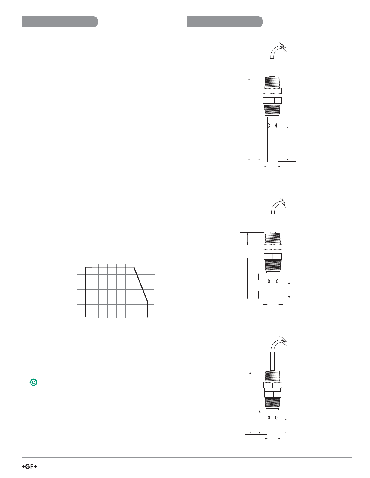
Specifi cations
59.3 mm
(2.33 in.)
73.7 mm
(2.90 in.)
140.7 mm
(5.54 in.)
15.9 mm
(0.625 in.)
21.5 mm
(0.85 in.)
35.8 mm
(1.41 in.)
102.7 mm
(4.05 in.)
15.9 mm
(0.625 in.)
15.9 mm
(0.625 in.)
26.8 mm
(1.13 in.)
109 mm
(4.29 in.)
41.9 mm
(1.65 in.)
Dimensions
General
Instrument Compatibility .......2850, 8850-3, 8860, 9900
Cable
4.6 m (15 ft) std., 3 conductor with shield, 22 AWG,
max length 30 m (100 ft). For resistivity measurements above
10 MΩ or below 20 °C, maximum cable length is 7.6 m (25 ft).
Process Connection
-1V ........................................
-1VD ......................................ISO 7/1-R 3/
3
/4 in. NPT
4
Wetted materials
Threaded fi tting.........................PVDF
Insulator ....................................PVDF
Insulator O-ring (2841, 2842) ...FPM
Electrode contacts ....................316L stainless steel
Shipping Weight
2839..........................................0.34 kg (0.74 lb)
2840, 2841, 2842......................0.30 kg (0.66 lb)
Performance
Accuracy ...................................±2% of cell value
Temp. measurement .................PT1000
Temp. response time (T):
2839 ......................................5 s
2840 ......................................10 s
2841 ......................................20 s
2842 ......................................30 s
Operating Pressure / Temperature
With thread engagement per ANSI B1.20.1
-10 ºC to 100 ºC @ 6.9 bar (14 ºF to 212 ºF @ 100 psi)
-10 ºC to 131 ºC @ 2.76 bar (14 ºF to 268 ºF @ 40 psi)
Storage Temperature ................ -20 ºC to 131 ºC
(-4 ºF to 268 ºF)
2839: 0.01 cm
2840: 0.1 cm
-1
-1
PSIBAR
100
7
75
5
50
3
2
25
°C
°F
-20-40
32 68
20
60
140
100 140
212
Standards and Approvals
• Manufactured under ISO 9001 for Quality,
ISO 14001 for Environmental Management and
OHSAS 18001 for Occupational Health and Safety.
• RoHS Compliant
China RoHS (Go to www.gfsignet.com for details)
284
2841: 1.0 cm-12842: 10.0 cm
-1
Signet PVDF Conductivity Sensors
3
Page 4

(100 M) (10 k)
2839 0.01 cm
-1
2841 1.0 cm
-1
2842 10.0 cm
-1
2840 0.1 cm
-1
0.010μs1μs10μs 100μs 1000μs 10,000μs 200,000μs
Conductivity Range (μS)
Signet Conductivity/Resistivity Electrode Ranges
Electrode Models
Cell Constant Selection
The nominal process value should be near the center of the range.
Ranges below are for use with Signet Conductivity Instruments:
• 2839 (0.01 cm
• 2840 (0.1 cm
• 2841 (1.0 cm
-1
): 0.010 to 100 μS (10 kΩ to 100 MΩ)
-1
): 1 to 1000 μS (1 MΩ to 1 kΩ)
-1
): 10 to 10,000 μS
• 2842 (10.0 cm-1): 100 to 200,000 μS
Custom Cell Certifi cate
The sensor was delivered from the factory with a calibration certifi cate.
The information provided on the certifi cate (custom cell constant and
temperature offset) should be entered in the transmitter/controller. See
individual product manual for details.
Installation
• Inspect threads to ensure integrity. Do not install an electrode with damaged threads.
• Apply sealant or PTFE tape to threads.
• Wetted materials include 316L stainless steel, PVDF and FPM (FPM O-ring inside 2841, 2842). Check
for chemical compatibility before installing electrode.
• Electrodes are supplied with 4.6 m (15 ft) of cable. It may be extended to a maximum 30 m (100 ft).
• For resistivity measurements above 10 MΩ or below 20 °C, maximum cable length is 7.6 m (25 ft).
• When using the 2850 Conductivity/Resistivity Sensor Electronics, maximum cable length is 4.6 m (15 ft).
• When using 9900, maximum cable length is 30 m (100 ft).
In-Line Installation
If the electrode is mounted vertically in a tee, do not recess the openings
inside the tee. Mounting upside down may help prevent air entrapment.
An oversized tee may also be helpful for inline installations.
At least 4 threads (ANSI B1.20.1) must be engaged to provide pressure
capacity per published specifi cations.
The preferred installation for in-line applications directs fl ow straight into the electrode.
This confi guration dislodges entrapped air bubbles, and provides the best continuous sampling of the fl uid content.
4
Signet PVDF Conductivity Sensors
Page 5

Fill with
3 to 4 in.
of sealant
8850-3
Conductivity Transmitter
locking ring
conduit base
8052 integral
adapter
electrode
Max cable length
15.2 cm (6 in.)
9900-1 Field Mount
with 8052 Integral Mounting Kit
and 9900.396 Angle Adjustment Adapter
Submersible Installation
1. Feed cable into watertight conduit.
2. Apply thread sealant to the electrode before threading conduit onto electrode. Avoid twisting the cable.
3. Secure cable with conduit or cable gland.
4. For additional defense against possible accumulation of condensation at the back seal area of the electrode,
fi ll the lower 75 mm to 100 mm (3 in. to 4 in.) of conduit or extension pipe with a fl exible sealant such as silicone.
3
/4 in. NPT or
ISO 7/1-R 3/
4
Integral Installation
In aerated vessels install the electrode in a stillwell to
prevent air from being trapped inside the electrode.
• 3-8052 Integral Kit and 3-9000.392-X Liquid Tight Connector kit are required. (See Parts and Accessories on back page).
• Cut the cable to approx. 15 cm (6 in.).
• Strip outer cable cover back 5 cm (2 in.).
• Strip each conductor to expose 1 cm (3/8 in.) of bare wire.
• Tin each conductor with solder for best results.
Signet PVDF Conductivity Sensors
5
Page 6

To 8850-3
Sensr Gnd
(SHIELD)
Iso. Gnd
(BLACK)
Temp. IN
(WHITE)
Signal IN
(RED)
14
13
12
11
To 8860
SHLD
ISO GND
TEMP 1
SGNL 1
RED
WHITE
BLACK
SHIELD (Gnd)
SHLD
ISO GND
TEMP 1
SGNL 1
RED
WHITE
BLACK
SHIELD (Gnd)
Ch 1
Ch 2
General Wiring
• Do not route electrode cable in conduit containing AC power wiring. Electrical noise may interfere with electrode signal.
• Routing electrode cable in grounded metal conduit will help prevent electrical noise and mechanical damage.
• Seal cable entry points to prevent moisture damage.
• For resistivity measurements above 10 MΩ or below 20 °C, maximum cable length is 7.6 m (25 ft).
ProcessPro Wiring
SmartPro Wiring
with 8052 Integral Mounting Kit
9900-1 Field Mount
and 9900.396 Angle Adjustment Adapter
9900.394
Direct Conductivity/Resistivity Module
Input Connector
Iso. Ground
Temp. In
Shield
Signal
Shield
White
9900 S3L Input
SHLD
DATA
GND
V+
via 2850 Sensor Electronics
White
Red
Black
Gnd
3
Data
2
1
V+
SW1
Sensr Gnd
(SHIELD)
4
CTS
3
2
ON
1
D3
Temp. IN
(WHITE)
Signal RTN
(BLK)
Signal IN
(RED)
6
Signet PVDF Conductivity Sensors
Black
Red
Page 7

Maintenance
Conductivity electrodes require little maintenance except for periodic cleaning in installations where contaminants are present.
• Keep metal surfaces clean and free of coatings.
2842 Insulator
Replacement Insulator, 2842 electrode only
• 2842 electrodes have a removable insulator so the internal cavity can be cleaned.
• After the insulator snaps into position it cannot be removed without damage.
• Order insulator replacement kit 3-2842.390 before attempting maintenance.
9 mm
(0.34 in.)
NOTE:
Contact the manufacturer for
11 mm
(0.44 in.)
14 mm
(0.55 in.)
replacement part number and cost.
25.4 mm (1.0 in.)
41 mm (1.6 in.)
3-2842.390 Insulator replacement kit
Insulator removal and replacement
A. Thread the screw into the insulator (8-32 thread).
B. Pull to remove the old insulator.
C. Clean any coating or deposits inside the electrode.
D. Insert the new insulator and press into place.
Electrode tip
(end view)
A
C
Internal contact
Electrode tip
(side view)
Electrode
B
Cotton swab
¥ Clean internal and external surfaces
8-32 thread for removal
Insulator
D
electrode tip
(side view)
New Insulator
Signet PVDF Conductivity Sensors
7
Page 8

Ordering Information
PVDF Conductivity Electrodes
Mfr. Part No. Code Description
3-2839-1V 159 001 810 Cell 0.01, 4.6 m (15 ft) cable, PVDF NPT threaded fi tting
3-2839-1VD 159 001 811 Cell 0.01, 4.6 m (15 ft) cable, PVDF ISO threaded fi tting
3-2840-1V 159 001 812 Cell 0.1, 4.6 m (15 ft) cable, PVDF NPT threaded fi tting
3-2840-1VD 159 001 813 Cell 0.1, 4.6 m (15 ft) cable, PVDF ISO threaded fi tting
3-2841-1V 159 001 814 Cell 1.0, 4.6 m (15 ft) cable, PVDF NPT threaded fi tting
3-2841-1VD 159 001 815 Cell 1.0, 4.6 m (15 ft) cable, PVDF ISO threaded fi tting
3-2842-1V 159 001 816 Cell 10.0, 4.6 m (15 ft) cable, PVDF NPT threaded fi tting
3-2842-1VD 159 001 817 Cell 10.0, 4.6 m (15 ft) cable, PVDF ISO threaded fi tting
2850 Conductivity/Resistivity Sensor Electronics
3-2850-51 159 001 398 Sensor Electronics, 3/4 in. NPT j-box, one input/one Digital (S3L) output
3-2850-52 159 001 399 Sensor Electronics, 3/4 in. NPT j-box, one input/one 4 to 20 mA output
3-2850-61 159 001 400 Sensor Electronics, Universal Mount j-box, one input/one Digital (S3L) output
3-2850-62 159 001 401 Sensor Electronics, Universal Mount j-box, one input/one 4 to 20 mA output
3-2850-63 159 001 402 Sensor Electronics, Universal Mount j-box, two inputs/two Digital (S3L) outputs
3-2850-51-39V 159 001 818 Integral 2850 system, Digital (S3L) output, 0.01 cell, PVDF NPT threads
3-2850-51-40V 159 001 819 Integral 2850 system, Digital (S3L) output, 0.1 cell, PVDF NPT threads
3-2850-51-41V 159 001 820 Integral 2850 system, Digital (S3L) output, 1.0 cell, PVDF NPT threads
3-2850-51-42V 159 001 821 Integral 2850 system, Digital (S3L) output, 10 cell, PVDF NPT threads
3-2850-51-39VD 159 001 822 Integral 2850 system, Digital (S3L) output, 0.01 cell, PVDF ISO threads
3-2850-51-40VD 159 001 823 Integral 2850 system, Digital (S3L) output, 0.1 cell, PVDF ISO threads
3-2850-51-41VD 159 001 824 Integral 2850 system, Digital (S3L) output, 1.0 cell, PVDF ISO threads
3-2850-51-42VD 159 001 825 Integral 2850 system, Digital (S3L) output, 10 cell, PVDF ISO threads
3-2850-52-39V 159 001 826 Integral 2850 system, 4 to 20 mA output, 0.01 cell, PVDF NPT threads
3-2850-52-40V 159 001 827 Integral 2850 system, 4 to 20 mA output, 0.1 cell, PVDF NPT threads
3-2850-52-41V 159 001 828 Integral 2850 system, 4 to 20 mA output, 1.0 cell, PVDF NPT threads
3-2850-52-42V 159 001 829 Integral 2850 system, 4 to 20 mA output, 10 cell, PVDF NPT threads
3-2850-52-39VD 159 001 830 Integral 2850 system, 4 to 20 mA output, 0.01 cell, PVDF ISO threads
3-2850-52-40VD 159 001 831 Integral 2850 system, 4 to 20 mA output, 0.1 cell, PVDF ISO threads
3-2850-52-41VD 159 001 832 Integral 2850 system, 4 to 20 mA output, 1.0 cell, PVDF ISO threads
3-2850-52-42VD 159 001 833 Integral 2850 system, 4 to 20 mA output, 10 cell, PVDF ISO threads
Replacement Parts
3-8050-1 159 000 753 Universal mount junction box
3-8052 159 000 188
3-9000.392-1 159 000 839 Liquid-tight connector kit, one set, 1/2 in. NPT
3-9000.392-2 159 000 841 Liquid-tight connector kit, one set, PG 13.5
3-9900.396 159 001 701 Angle Adjustment Adapter
5523-0322 159 000 761 Sensor cable (per ft), 3 conductor plus shield
3
/4 in. Integral mounting kit
Georg Fischer Signet LLC, 3401 Aero Jet Avenue, El Monte, CA 91731-2882 U.S.A. • Tel. (626) 571-2770 • Fax (626) 573-2057
For Worldwide Sales and Service, visit our website: www.gfsignet.com • Or call (in the U.S.): (800) 854-4090
For the most up-to-date information, please refer to our website at www.gfsignet.com
3-2840.090-1 Rev. B 01/15 English © Georg Fischer Signet LLC 2015
 Loading...