

Page 1
CSA is cross sectional area.
*
www.gfsignet.com
Technical Reference Section: Conductivity/
Resistivity
Principle of operation
AC
+
Half Cells
Voltage
+
z
+
+
+
+
+
+
+
+
+
+
+
+
+
+
1cm
1cm
+
+
2
-1
Graphs
221
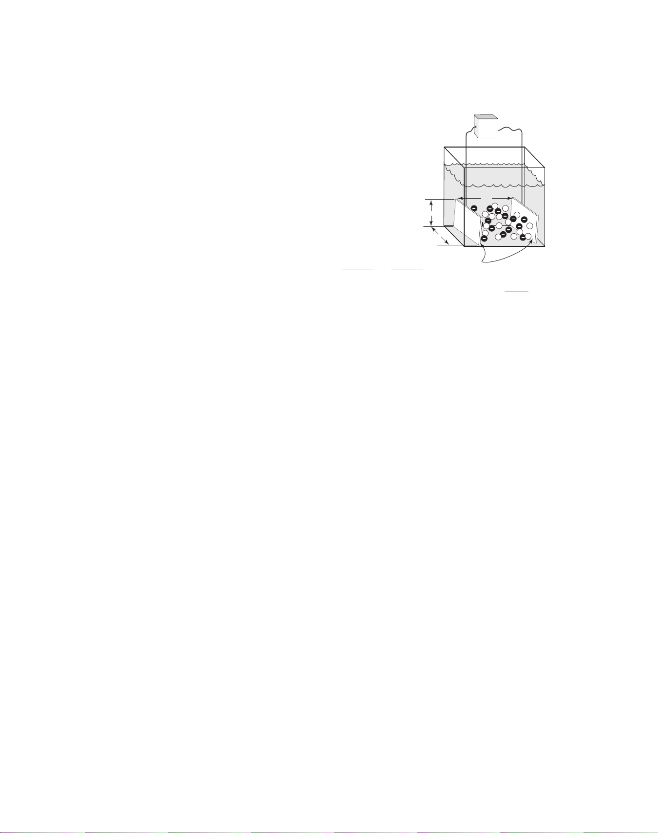
Most conductivity electrodes consist
of two measuring half-cells. The
geometry of the half-cells can be tailored to provide highly accurate measurements over a specific conductivity range. Cell constants
help to
describe electrode geometry for the
purpose of selecting the appropriate
x
electrode for a given application. A
cell constant is defined as the length
y
between the two half-cells divided by
the area of the cells.
Conductivity Cell Constant = =
Length
CSA*
z
xy
As an example, When x = y = z = 1cm the cell constant becomes = 1cm
Solutions of very low conductivity (high resistivity) such as ultra-pure water are
best measured with half-cells that are very close together (i.e., cell constant =
-1
0.01cm
). Highly conductive solutions should be measured with half-cells that
are farther apart and that have relatively little cross sectional area between
-1
them (i.e., cell constant = 20.0cm
Temperature Compensation
The conductivity of a solution is
highly dependent upon temperature.
Therefore, conductivity measurements are almost always converted
to an equivalent conductivity at the
common reference temperature of
25°C (77°F). This is accomplished by
means of temperature compensation algorithms in the instruments,
which require temperature as well as
conductivity measurement input. To
simplify and facilitate this requirement all Signet conductivity electrodes contain high-quality temperature sensing elements intelligently
positioned for quick and accurate
response.
).
siderably with the ionic composition
of the solution and can range from
less than 1% to more than 3% per °C.
This is true of regional ground water
sources as well as for other solutions
such as brackish water, acids and
bases. Signet instruments allow the
entry of custom linear compensation
coefficients for these applications.
See the instruction manual of any
Signet conductivity instrument for
details.
The conductivity or resistivity of pure
water is not a linear function with
respect to temperature. In fact, the
latest Signet conductivity instruments utilize a sophisticated polynomial to compensate for the peculiar
effects. For seamless measurement
Temperature effects on conductivity
are more or less linear for normal
water-based solutions, hovering
around 2% per °C. However, the
actual linear relationship varies con-
accuracy all current Signet conduc-
tivity instruments switch automati-
cally between linear and pure-water
compensation as certain measure-
ment thresholds are crossed.
Temperature Compensation Exception
One exception to the requirement for temperature compensation has been established by USP (United States Pharmacopeia), which prescribes limits of acceptability for ultra-pure water quality based upon non-compensated measurements.
This methodology is used to eliminate measurement variances that may result
from differences in the pure-water temperature compensation algorithms used by
different manufacturers of conductivity measurement equipment. A more thorough treatment of the USP standard and instrument functionality can be found in
the instruction manuals of the following Signet conductivity instruments: Model
8900 Multi-Channel, Multi-Parameter Controller (Appendix D), model 8860 Dual
Channel Conductivity/Resistivity Controller.
Choosing
Products
Instrument
Multi-Pa-
rameter
Flow
pH/ORP
Conductivity/
Resistivity
Pressure, Level
Temperature,
Products
Other
Installation
Wiring &
Reference
Technical
Temperature/
Pressure
of Terms
Glossary
Reference
Part No.
Index
Page 2

p
p
Relay Information
The two most common methods of controlling a process are “on/off” and “proportional” control. In on/off control, relay setpoints are defined as either high
or low limits on the process variable. When the measurement value reaches a
limit the relay is energized, typically for the purpose of opening a valve or starting a pump to introduce a chemical reagent to the process. This should cause
the measurement value to change in the direction of the setpoint as shown in
these on/off control diagrams:
High limit on/off relay control
= HI setpoint
= Hysteresis
= Relay energized
= Relay de-energized
pH
Notice the relay will not de-energize
until the setpoint is exceeded by the
hysteresis value. This is a programmable value and is primarily used to
prevent ”relay chatter”, which occurs
if a relay is set to energize and deenergize at the same value. Because
of hysteresis, and because reagent
delivery is fairly constant while the
relay is energized, a condition known
as “overshoot” is inherent to the on/
off control method. Overshoot refers
to the introduction of more chemical
reagent than is absolutely necessary
for achieving a desired adjustment to
the process value, and can be expensive over time.
Proportional control is a popular
alternative to the on/off control
method. This method typically makes
use of variable-rate metering pumps
to reduce overshoot and improve
precision. Establishing a proportional control scenario requires the
selection of setpoint(s), deviation
Low limit on/off control
pH
= LO setpoint
= Hysteresis
= Relay energized
= Relay de-energized
range(s) and maximum pulse rates.
The example shown here illustrates
how two relays in ”pulse mode” can
be used to proportionally control pH
within a desired range, or to a single
setpoint. This is called “Dual Proportional Control”. Of course, a single
relay in proportional pulse mode can
be used to establish a high or low
limit and will also reduce overshoot.
Metering pumps are idle at and between setpoints. When a setpoint is
exceeded, the pump begins delivering
reagent at a rate proportional to the
difference between the measurement
value and the setpoint. The larger
the difference, the faster the delivery. The programmed deviation value
defines how quickly the maximum
pulse rate is reached. Depending on
the input requirements of the metering pump, proportional control can
also be accomplished with scaleable
4 to 20 mA outputs instead of pulsing
relays or open collectors.
Dual proportional pulse relay control
Maximum Pulse Rate
0
pH
Deviation=
5.30 pH
LO
5.30
H
HI
7.50
H
Deviation=
3.50 pH
11.00
pH
222
14
pH
pH
Maximum Pulse Rate
Deviation=
5.20 pH
0
2.10
pH
LO and HI
7.30 pH
Deviation=
4.90 pH
12.20
pH
14
pH
www.gfsignet.com
Page 3

Open Collector Output
Many Signet instruments and sensors feature “Open Collector Outputs” for
purposes of signal transmission, alarming, control signal output, etc. Although
such outputs allow for a lot of wiring flexibility, care must be taken not to
destroy the circuits via incorrect polarity, over-voltage, transients or current
overload. Below is an explanation of proper wiring and dimensioning of related
circuit components. Please note that the following recommendations may or
may not apply to other manufacturer’s equipment.
1. Function
Open Collector (“OC”) outputs are low powered, solid state switches.
Although the term “Open Collector” stipulates the use of bipolar transistors
(NPN-type or PNP-type) as a switch, nowadays Field Effect Transistors (FET
or MOSFET) are used. Unlike electromechnical switches (e.g. pushbuttons
or dry contact relays) these OC switches are very fast, use little power, are
inexpensive, do not bounce and do not wear. However, OC’s are also more
limited in terms of voltage and current rating as well as being polarized
(i.e. they have a “plus” and “minus” terminal and thus DC only switching
capability). They are less tolerant to overload abuse than electromechanical
devices. Usually these switches have higher resistance and voltage drop.
2. Sensor Wiring
A typical example of the need for high speed switching capability is the
OC frequency output of Signet flow sensors like 3-2536 or 3-2540. Signal
frequencies can reach several hundred pulses per second while voltage and
current requirements are small enough, allowing the use of a transistor
switch. For each output pulse this switch connects the signal output to the
negative supply or ground terminal of the sensor and is therefore an “NPN”
style output. Signet does not produce sensors with PNP style outputs (which
connect the signal output internally to the positive supply terminal).
Choosing
Products
Instrument
Multi-Pa-
rameter
Flow
pH/ORP
Conductivity/
Resistivity
Pressure, Level
Temperature,
Products
Other
Do not exceed the absolute
maximum voltage rating of
the OC output as listed in
the sensor specifications,
normally 27 or 30 Volt, DC
only. This includes changes
to power line fluctuations,
transients or power supply
instability, otherwise damage to the OC will occur.
Most indicating instruments or control system inputs require a signal
voltage of 0 to 5V (TTL or CMOS logic levels) or 0 to 24V. Therefore, Open
Collector output circuits must be complemented with a “Pull-Up-Resistor”
to function properly. Please see the following example diagram for wiring
with a PLC input:
+5V to
Gnd
+24V
Power
Supply
V+
Signet
Sensor/Instrument
Signal
OCSwitch
Gnd
Pull-UpResistor
Input
Gnd
PLC
Please note that the voltage connected to the positive sensor supply (V+)
must correspond to the required high-level PLC input voltage (i.e. if the
high-input voltage of the PLC is 24V, then the pull-up must be supplied with
24V). If the input is “TTL-Level” or “CMOS-Level”, that means 5V for high
level, then the pull-up should not be connected with a supply higher than 5V.
Signet instruments already have the pull-up-resistor and the sensor power
supply built into the instrument. No external pull-up-resistors are required.
Installation
Wiring &
Reference
Technical
Temperature/
Pressure
Graphs
of Terms
Glossary
Reference
Part No.
Index
www.gfsignet.com
223
Page 4

Open Collector Output (continued)
3. Instrument Output Wiring
Open collector control and alarm outputs on Signet instruments (i.e.
ProcessPro
instrument’s power supply. That means these can be used in the above
mentioned NPN configuration as well as in PNP configuration, if required.
Below are a few sample circuits:
• PLC Wiring “NPN” style
Signet
Instrument/Sensor
OCSwitch
• Alarm circuit or alarm lamp wiring to a single Signet instrument
®
or ProPoint™ series) are electrically isolated from the
+5V to
+24V
OC+
OC-
Pull-UpResistor
Input
Gnd
PLC
Gnd
Power
Supply
Signet
Instrument
OCSwitch
OC+
Alarm
Circuit
V+
Gnd
Power
Supply
• Alarm circuit or alarm lamp wiring to serve multiple Signet instruments
- Triggers the alarm if any one of the instruments open collector outputs are on.
Signet
Instrument
OCSwitch
OC+
Signet
Instrument
OCSwitch
OC+
Signet
Instrument
OCSwitch
OC+
Alarm
Circuit
V+
Gnd
Power
Supply
224
www.gfsignet.com
Page 5

Open Collector Output (continued)
4. Voltage and Current Limitation
As mentioned before, the supply voltage in the OC output circuit MUST
be limited to the specified maximum OC voltage (see operating manual
for specific instrument). The use of a quality regulated 5V, 12V or 24V
(depending on the application) power supply is recommended.
The current through the Open Collector switch must be limited. Typical OC
outputs allow only for 10 to 50mA switch current (please consult manual).
Exceeding this current limit can burn out the OC output components
immediately. Please see the following section on how to dimension the
loads.
5. Load and Pull-Up/Down Resistor Considerations
By utilizing basic arithmetic and Ohm’s law, one can determine the safe
limits of load resistance. When the OC switch is closed, almost the entire
supply voltage is applied to the load, (i.e. the pull-up or pull-down resistor,
the alarm horn input, a potential power relay coil or annunciator lamp). The
resulting current through the load and through the OC switch, as well, can
be calculated as:
(Current) = (Supply Voltage)/(Load Resistance)
Choosing
Products
Instrument
Multi-Pa-
rameter
Flow
pH/ORP
Conductivity/
Resistivity
Pressure, Level
Temperature,
• Example 1:
The supply voltage is 24V and a
pull-up-resistor of 10kΩ is used.
Current is 24/10,000 = 2.4mA
(If the OC current rating is 10mA, then in this
example, it would be considered safe.)
• Example 2:
The supply voltage is 12V and a horn
with a resistance of 100Ω is used
Current is 12/100 = 120mA
(Even if the OC current rating is 50mA, this load
will damage the instrument)
6. Transient Protection
There are several “difficult” load cases that must be considered:
• Inductive loads:
These can be power relay
or other solenoids, motors,
alarm horn coils, etc. Such
loads generate very high
voltage spikes everytime
the load switches. If such a
load is unavoidable, the use
of transient suppression
• Capacitive loads:
This type of load should be
rare but can occur if the load
contains an internal power
supply/regulator that is fed
from the output circuit. In such
a case, it must be assured that
the in-rush current does not
exceed the OC current rating.
components, or Signet RCFilters (3-8050.396), or
snubbers, wired parallel to
the load is required. This is
critical, as a single transient
pulse may destroy the output.
• Incandescent lamps:
Such lamps have a very high
start-up current until the
filament glows and the current
settles to the specified value.
The use of incandescent
lamps on an OC output is not
recommended. An LED type
annunciator should be used
instead.
Products
Other
Installation
Wiring &
Reference
Technical
Temperature/
Pressure
Graphs
of Terms
Glossary
Reference
Part No.
www.gfsignet.com
Index
225
Page 6

Open Collector Output (continued)
7. “Active High” and “Active Low” Setting
Depending on the desired function of the circuit attached to the OC output, it
may be necessary to have the OC output switch turned “on” or “off” when the
criteria for the activation of this output are met.
By default, Signet instruments are set to operate in “active low” mode.
This means when the user-defined condition for the activation is met (e.g.
exceeding of an alarm limit) the OC switch is turned “on”. If wired as standard
“NPN-style” output (see previous page) the logic level of the attached control
system or PLC input consequently becomes “low” logic level.
If a high input logic level is required for activation, it can be accomplished by
changing the OC output function to “active high” in the menu system of the
instrument. Most Signet instruments allow for this option.
8. Fail-Safe Behavior
No matter what the setting, most OC outputs of Signet instruments turn off
when the instrument loses power. This must be taken into account when
evaluating system failure consequences. If the system layout requires a
“closed” or “on” condition for the output in case of power loss, a mechanical
dry contact relay (NC contacts) must be used instead of the OC output.
226
www.gfsignet.com
 Loading...