

Page 1
Signet 2724-2726 and 2734-2736 Series DryLoc pH and ORP Electrodes
*3-2724.090*
3-2724.090 Rev. 20 10/19
Operating Instructions
Description
English
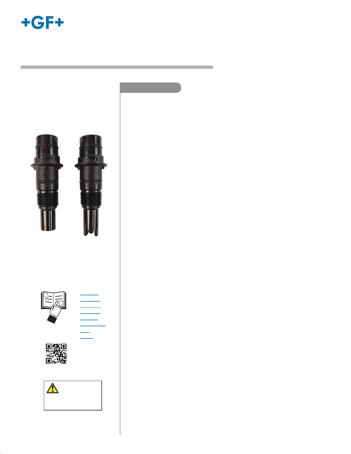
2724 & 2725
2734 & 2735
Flat Style
Electrode
2726 & 2736
Protected
Bulb Style
Electrode
Signet General Purpose 2724-2726 and High Performance 2734-2736 series of pH and
ORP electrodes are designed to minimize maintenance time and maximize performance
longevity and value.
• The unique DryLoc® connector provides quick assembly and a secure connection
featuring gold-plated contacts and an O-ring seal.
• The patented design features a lengthened reference chamber pathway to extend
the operational life of the electrode.
• Wetted materials are selected to withstand a wide range of industrial applications.
• Multiple mounting features address the need for installation fl exibility.
These electrodes can be threaded into ¾ in. NPT or ISO 7/1 R¾ inch pipe fi ttings,
submerged in a tank, or mounted into familiar Signet installation fi ttings ranging
from 0.5" to 4" size.
• Combine the 2724-2726 or 2734-2736 electrodes with the Signet 2751 Smart
Sensor Electronics or the 2760 Preamplifi er to provide a 4 to 20 mA loop to a
Programmable Logic Controller (PLC), SCADA system, or datalogger.
• Memory chip enabled to store Manufacturing, Calibration and Operational Data.
- Manufacturing Information (Serial Number, Model Number, and Factory
Glass Impedance).
- Calibration Information (Factory Calibration pH/ORP, Factory Calibration
Temperature, User Calibration pH/ ORP, User Calibration Temperature,
Offset pH/ORP and Slope Effi ciency % pH/ORP).
- Operational Data (Sensor Runtime Hours, Minimum & Maximum Measured
pH/ ORP, and Minimum and Maximum Measured Temperature).
• English
• Deutsch
• Français
• Español
• Italiano
• Português
• 中文
• 뭨펯
California Prop. 65
WARNING:
Cancer and Reproductive Harm
www.p65warnings.ca.gov
• For more fl exibility and unique features, pair the 2724-2726 or 2734-2736 series
a 2751 Smart Sensor Electronics and the 9900 Transmitter, 9950 Dual Channel
Transmitter or the 0486 Profi bus Concentrator. Additional features include electrode
health monitoring and diagnostics through glass impedance measurement, broken
glass detection and reference impedance measurement. Convenient remote
calibration eliminates the hassle of fi eld calibration.
• Connect up to six 2724-2726 or 2734-2736 electrodes to one 8900 Multi-Parameter
Controller with six 2751 pH/ORP Sensor Electronics using digital (S3L) serial data
output.
• Connect up to two 2724-2726 or 2734-2736 electrodes to one 9950 Dual Channel
Transmitter with two 2751 pH/ORP Sensor Electronics using digital (S3L) output for a
truly amazing set of features, options and measurements.
• The 2724-2726 electrodes are recommended for general purpose applications.
• The High Performance 2734-2736 electrodes are recommended for harsh
applications.
• The 2734-2736 electrodes utilize advanced reference technology and special
formulation glass to extend electrode life in all applications.
with
Page 2
Warranty Information
Chemical Compatibility
Refer to your local Georg Fischer Sales offi ce for the most current
warranty statement.
All warranty and non-warranty repairs being returned must include
a fully completed Service Form and goods must be returned to your
local GF Sales offi ce or distributor.
Product returned without a Service Form may not be
warranty replaced or repaired.
Signet products with limited shelf-life (e.g. pH, ORP, chlorine
electrodes, calibration solutions; e.g. pH buffers, turbidity standards
or other solutions) are warranted out of box but not warranted
against any damage, due to process or application failures (e.g. high
temperature,
glass,
chemical poisoning, dry-out) or mishandling (e.g. broken
damaged membrane, freezing and/or extreme temperatures).
Product Registration
Thank you for purchasing the Signet line of Georg Fischer
measurement products.
If you would like to register your product(s), you can now register
online in one of the following ways:
• Visit our website www.gfsignet.com and
click on Product Registration Form.
• If this is a pdf manual (digital copy), click here.
Safety Information
1. Use appropriate eye, face, hand, body and/or respiratory protection
when using chemicals or solvents.
2. Prior to installation or removal:
• Depressurize and vent system
• Drain below sensor level.
3. Confi rm chemical compatibility before use.
4. Do not exceed the max. temperature/pressure specifi cations.
5. Do not alter product construction.
If installing into a threaded connection:
6. Inspect threads to ensure integrity. Do not install a sensor that has
damaged threads.
7. Apply PTFE tape to the 3/4" M-NPT or ISO 7/1-R 3/4 process
connection threads in accordance with industry practices.
8. HAND TIGHTEN the sensor into the process connection.
DO NOT USE TOOLS.
Caution / Warning / Danger
Indicates a potential hazard.
Failure to follow all warnings may lead to equipment
damage, injury, or death
Personal Protective Equipment (PPE)
Always utilize the most appropriate PPE during
installation and service of Signet products.
Pressurized System Warning
Sensor may be under pressure, take caution to vent
system prior to installation or removal.
Failure to do so may result in equipment damage and/or
serious injury.
Hand Tighten Only
Overtightening may permanently damage product
threads and lead to failure of the retaining nut.
Do Not Use Tools
Use of tool(s) may damage product beyond repair and
potentially void product warranty.
Note / Technical Notes
Highlights additional information or detailed procedure.
Do Not Freeze
Products are temperature sensitive and may contain
DO NOT
FREEZE
freezable liquids.
Freezing damage to pH, ORP, and Chlorine electrodes
voids product warranty.
The retaining nuts of pH and ORP sensors are not designed
for prolonged contact with aggressive substances.
Strong acids, caustic substances and solvents or their
vapor may lead to failure of the retaining nut, ejection of the
sensor and loss of the process fl uid with possibly serious
consequences, such as damage to equipment and serious
personal injury. Retaining nuts that may have been in
contact with such substances, e.g. due to leakage or spilling,
must be replaced.
• The use of this product assumes
operators are trained and familiar
with this type of device.
• Operators should be knowledgeable
of the potential risks associated with
pressurized piping systems.
• Operators MUST follow all
necessary safety procedures.
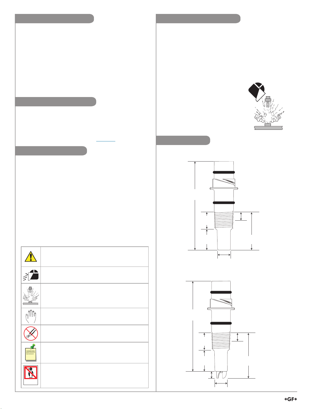
Dimensions
2724, 2725, 2734, & 2735 Flat Glass Electrode
Threads:
¾ in. NPT or
95.76 mm
(3.77 in.)
19.05 mm
(0.75 in.)
25.4 mm
(1.0 in.)
2726 & 2736 Protected Bulb Glass Electrode
95.76 mm
(3.77 in.)
19.05 mm
(0.75 in.)
25.4 mm
(1.0 in.)
8.89 mm
(0.35 in.)
ISO 7/1 R¾
6.35 mm
(0.25 in.)
44.45 mm
(1.75 in.)
18.3 mm
(0.72 in.)
Threads:
¾ in. NPT or
ISO 7/1 R¾
6.35 mm
(0.25 in.)
53.34 mm
(2.1 in.)
18.3 mm
(0.72 in.)
2
Signet 2724-2726 and 2734-2736 Series pH and ORP Electrodes
Page 3
Specifi cations
General
Compatibility ................... 2751 pH/ORP Smart Sensor Electronics,
2760 pH/ORP Preamplifi er
(2724-2726 3K Balco only)
pH Temp. Sensor:
Pt1000 ............................ Compatible with 2751 pH/ORP Smart
Sensor Electronics
Connection to ............. PLC, 9900 Transmitter,
8900 Multi-Parameter Controller
9950 Dual Channel Transmitter
3 K Balco ..................... Compatible with 2760 Preamplifi er
Connection to ............. 8750 pH/ORP Transmitter
Process Connection ....... ¾ in. NPT, ISO 7/1 R¾ threads,
or Signet Installation Fittings 0.5" to 4" sizes
Wetted Materials
pH (2724 & 2726) ........... Ryton (PPS), glass, UHMW PE, FKM
ORP (2725) .................... Ryton (PPS), glass, UHMW PE, FKM,
Platinum
pH (2734 & 2736) ........... Ryton (PPS), glass, PTFE, FKM
ORP (2735) .................... Ryton (PPS), glass, PTFE, FKM, Platinum
Shipping Weight ........... 0.25 kg (0.55 lb)
Performance
Effi ciency
2724-2726 ...................... > 97% @ 25 °C (77 °F)
2734-2736 ...................... > 95% @ 25 °C (77 °F)
• Effi ciency indicates the "wellness" of a new electrode.
• Effi ciency is measured by comparing the actual slope (mV/pH) at
25 °C to the theoretical output of 59.16 mV/pH.
• An effi ciency of 95% to 100% is equivalent to a slope of
56.20 to 59.16 mV/pH.
Measuring Range
pH ................................... 0 to 14
ORP ................................ ±2000 mV
3-2726-LC ......................
Low Conductivity fl uids (20 to 100 S/cm)
20 S/cm ................. Flow must be less than 150 ml/min. in a
properly grounded system
3-2724-HF, 3-2726-HF, 3-2734-HF, 3-2736-HF:
Hydrofl uric acid resistant glass, pH 6 or below; trace HF 2%
For applications where hydrofl uoric acid, in concentrations of 2%
or less, will attack standard pH glass in situations where process
upsets may temporarily drop to these pH levels.
Environmental Requirements
Operating Temperature
2724-2726* .............................. -10 °C to 85 °C (14 °F to 185 °F)
2734-2736* .............................. 10 °C to 100 °C (50 °F to 212 °F)
*Best performance for 3-2724-HF, 3-2726-HF, 3-2734-HF,
3-2736-HF is above 10 °C (50 °F)
Note: The Sensor Electronics must be remotely mounted when
the temperature exceeds 85 °C (185 °F)
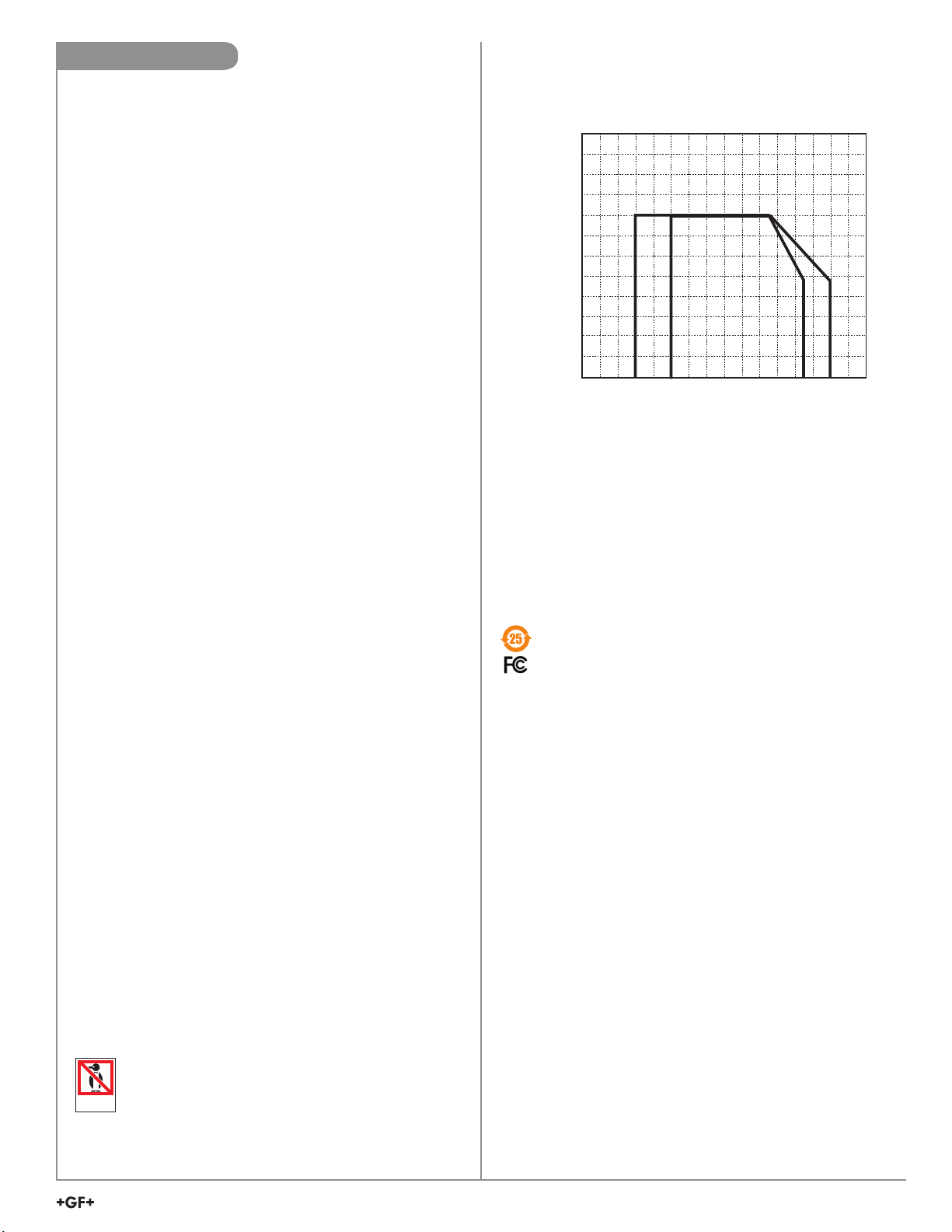
Maximum Temperature and Pressure Rating
10.3
150
8.6
125
6.9
100
273X
272X
5.2
75
3.4
50
1.7
25
(bar)(psi)
0
°C
-40
°F
-40 -4 32
Standards and Approvals
• CE, WEEE, RoHS Compliant
• Manufactured under ISO 9001 for Quality,
ISO 14001 for Environmental Management and
OHSAS 18001 for Occupational Health and Safety.
China RoHS (Go to www.gfsignet.com for details)
Declaration of Conformity according to FCC Part 15
This device complies with Part 15 of the FCC rules.
Operation is subject to the following two conditions:
(1) This device may not cause harmful interference, and
(2) This device must accept any interference received,
including interference that may cause undesired operation.
REACH Information Obligation: in accordance with
Article 33 of the European REACh Regulation (EC)
No. 1907/2006, the substances Lead and Acrylamide
are present in the glass matrix and as a polymerized gel
respectively; in a concentration >0.1% (w/w). During normal
use, the articles do not pose any risks and no additional
information is required for safe use.
-20
272X
0
273X
20
68
40
60
104
140 176 212
80
100
120
248
Operating Pressure Range
2724-2726:
• 0 to 6.9 bar (0 to 100 psi) @ -10 °C to 65 °C (14 °F to 149 °F)
• Linearity Derated 6.9 to 4.0 bar (100 to 58 psi) @
65 °C to 85 °C (149 °F to 185 °F)
2734-2736:
• 0 to 6.9 bar (0 to 100 psi) @ 10 °C to 65 °C (50 °F to 149 °F)
• Linearity Derated 6.9 to 4.0 bar (100 to 58 psi) @
65 °C to 100 °C (149 °F to 212 °F)
Recommended storage temperature
pH/ORP electrodes ................. 0 °C to 50 °C (32 °F to 122 °F)
• The electrode glass will shatter if shipped or stored at
temperatures below 0 °C (32 °F).
• The performance life of the electrode will be shortened
DO NOT
FREEZE
if stored at temperatures above 50 °C (122 °F).
Signet 2724-2726 and 2734-2736 Series pH and ORP Electrodes
3
Page 4
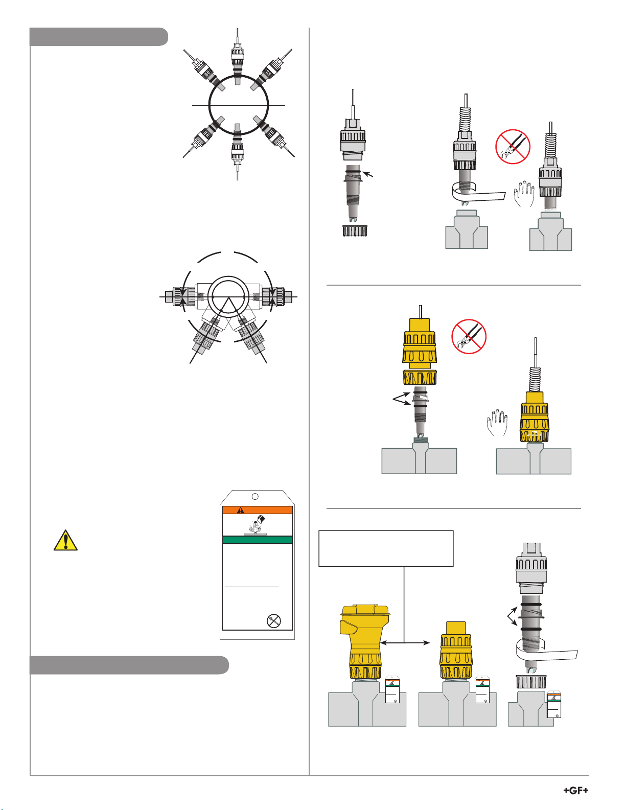
In-Line Installation
1. The electrode can be
mounted at any angle.
Yes
Yes
2. Avoid air pockets and sediment.
3. The fi tting must place the
electrode in the fl ow but
0°
Horizontal
must not bottom out in the pipe.
4. Select a Signet installation
fi tting (0.5" to 4" size range) for
convenience. Lightly lubricate
Yes
Yes
Yes
O-ring with a non-petroleum
based lubricate (grease)
compatible with the system.
NOTE:
When mounting in a standard threaded fi tting,
the electrode must be mounted horizontal to 60 degrees
below horizontal position only:
5. Use the ¾ in. M-NPT or
ISO 7/1-R ¾ threads on
NO NO
NO
the electrode body to
install the electrode into
reducing tee fi ttings.
6. Inspect threads to ensure
YESYES
integrity. Do not install an
electrode with damaged
threads.
NO
270°
7. Apply PTFE tape to
the M-NPT or ISO 7/1-R ¾ process connection threads, in
accordance with industry standards.
8. Use piping installation hardware with smooth,
well-fi nished threads to facilitate the installation.
9. If necessary, the pipe should be plumbed with a depression
(trap) so liquid is maintained around the electrode tip.
10. Hand-tighten the electrode into the process connection.
Do not use any tools to install the electrode.
The use of wrenches, pliers or similar may over-stress the
sensor body and lead to breakage and
subsequent spillage of the process liquid.
3-2700.615 (B-04/08)
WARNING
CAUTION:
A broken sensor may be
ejected forcefully from the fi tting
and can cause severe injury.
11. The safety instructions have an
adhesive label and should be
placed near the sensor.
SAFETY INSTRUCTIONS
1. Use appropriate eye, face, hand, body
and/or respiratory protection when using
chemicals or solvents
2. Prior to installation or removal:
a. Depressurize and vent system
b. Drain below sensor level
3. Confirm chemical compatibility before use
4. Do not exceed the maximum
temperature/pressure specifications
5. Do not alter product construction
If installing into a threaded connection:
6. Inspect threads to ensure integrity. Do not
install a sensor that has damaged threads
7. Apply PTFE tape to the process connection
threads in accordance with industry
practices
8. Hand tighten the sensor into the process
connection. DO NOT USE TOOLS
Failure to follow
these instructions may
result in personal injury
See peel & stick warning label on back!
Attach near sensor
Yes
3-2751-X
3-2760-X
Submersible
Preamplifi er
Lightly lubricate
O-ring with a
non-petroleum
based lubricate
(grease)
compatible with
the system.
Flexible conduit
PTFE tape
Fitting (customer supplied)Electrode
3-2751-X,
3-2760-X1
In-Line
Preamplifi er
Lightly lubricate
O-ring with a
non-petroleum
based lubricate
(grease)
compatible with
the system.
Electrode
Flexible
conduit
Signet Installation Fitting DN15 to DN100 (½ in. to 4 in.)
Do not use as a handle!
• Do not use tools or lubricant
to install yellow retaining cap.
• Do not overtighten.
Lightly lubricate O-ring
with a non-petroleum
based lubricate
(grease) compatible
with the system.
Low Conductivity Installation
• The 3-2726-LC pH electrodes can be used in
low conductivity water of less than 100 S.
• When used in the range of 20 to 100 S,
the fl ow range must not exceed 1 m/s (3 ft/s) velocity.
• When used in liquids of less than 20 S,
the fl ow range must not exceed 150 ml/min;
the sensor should also be mounted in a well grounded cell.
4
Signet 2724-2726 and 2734-2736 Series pH and ORP Electrodes
3-2700.615 (B-04/08)
WARNING
SAFETY INSTRUCTIONS
1. Use appropriate eye, face, hand, body
and/or respiratory protection when using
chemicals or solvents
2. Prior to installation or removal:
a. Depressurize and vent system
b. Drain below sensor level
3. Confirm chemical compatibility before use
4. Do not exceed the maximum
temperature/pressure specifications
5. Do not alter product construction
If installing into a threaded connection:
6. Inspect threads to ensure integrity. Do not
install a sensor that has damaged threads
7. Apply PTFE tape to the process connection
threads in accordance with industry
practices
8. Hand tighten the sensor into the process
connection. DO NOT USE TOOLS
Failure to follow
these instructions may
result in personal injury
SAFETY INSTRUCTIONS
1. Use appropriate eye, face, hand, body
and/or respiratory protection when using
chemicals or solvents
2. Prior to installation or removal:
a. Depressurize and vent system
b. Drain below sensor level
3. Confirm chemical compatibility before use
4. Do not exceed the maximum
temperature/pressure specifications
5. Do not alter product construction
If installing into a threaded connection:
6. Inspect threads to ensure integrity. Do not
install a sensor that has damaged threads
7. Apply PTFE tape to the process connection
threads in accordance with industry
practices
8. Hand tighten the sensor into the process
connection. DO NOT USE TOOLS
these instructions may
result in personal injury
GF Signet Installation Fittings 0.5" to 4"
3-2700.615 (B-04/08)
WARNING
Failure to follow
Customer supplied Tee,
or Reducing Tee
PTFE tape
3-2700.615 (B-04/08)
WARNING
SAFETY INSTRUCTIONS
1. Use appropriate eye, face, hand, body
and/or respiratory protection when using
chemicals or solvents
2. Prior to installation or removal:
a. Depressurize and vent system
b. Drain below sensor level
3. Confirm chemical compatibility before use
4. Do not exceed the maximum
temperature/pressure specifications
5. Do not alter product construction
If installing into a threaded connection:
6. Inspect threads to ensure integrity. Do not
install a sensor that has damaged threads
7. Apply PTFE tape to the process connection
threads in accordance with industry
practices
8. Hand tighten the sensor into the process
connection. DO NOT USE TOOLS
Failure to follow
these instructions may
result in personal injury
Page 5

Signet Installation Fittings
Type Description Type Description
Plastic tees
PVC saddles
• Available in ½ in. to 4 in. sizes
• PVC, CPVC w/solvent cement socket
• PVDF or PP w/union end fittings
• Available in 2 in. to 4 in. sizes
• Requires 1-7/16 in. hole in pipe
Carbon steel
weldolets
Carbon steel
threaded tees
• Available in 2 in. to 4 in. sizes
• Requires 1-7/16 in. hole in pipe
• Install by certified welder only
• Available in ½ in. to 2 in. sizes
• Female NPT ends
Iron
strap-on
saddles
• Available in 2 in. to 4 in. sizes
• Requires 1-7/16 in. hole in pipe
Universal
pipe adapters
Removing from In-Line Installation
In-line removal Instructions:
• The use of this product assumes
that operators are trained and are
familiar with this type of device.
• They should be knowledgeable of
1. Depressurize and vent the piping system.
2. Drain the system to below sensor level.
3. Wear safety goggles or face shield during removal.
the potential risks associated with
pressurized piping systems.
• Operators MUST follow all
4. Practice proper Lock Out/ Tag Out procedures when the sensor
necessary safety procedures.
Submersible Installations
The user must supply the following hardware
to complete a submersible installation:
• ¾ in. Pipe, ¾ in. (DN 20) Male Adapter, Liquid Tight
Connection at top of pipe assembly
• Wiring junction box
• Pipe clamps (quick-release type recommended)
• Tank fl ange for closed tanks
• Silicone Caulking Sealant & PTFE Tape
2724-2726 / 2734-2736 with 2751/2760 pH/ORP Sensor Electronics
• Use for installation in pipes >4 in. (1¼ in. NPT)
• PVC, CPVC, or PVDF versions
• Specify socket or 1¼ inch NPT male threads
• Contact factory for support
Use all appropriate eye, face, hand, body and/or respiratory
protection when working with chemicals or solvents.
is removed for maintenance to prevent accidental opening and
exposure to potentially hazardous chemicals.
Technical Note:
• Mount the electrode near tank outlets, away from reagent
addition areas.
• Use the ¾ in. (
ISO 7/1-R ¾
) threads at the top of the
preamplifi er to run the cable inside pipe or conduit.
• Place the electrode tip in pH 4 Buffer for temporary storage
during system maintenance to avoid dehydration. For
long term storage place the electrode tip in 3.0 mol/L KCl
solution.
1
2
3
3
4
Fill with
Lubricate
O-ring
The Signet pH/ORP electrodes are designed to install in tanks by attaching conduit to the ¾ in. (
3 to 4 in.
caulking
of
sealant
Open
tanks
ISO 7/1-R ¾ )
Closed
tanks
threads at
the top of the accompanying preamplifi er or sensor electronics:
1. The O-ring at the top of the electrode fi ts very tightly into the preamplifi er. Use a small amount of non-petroleum based
lubricant to assist the assembly.
2. To prevent moisture from migrating into the preamplifi er, backfi ll the conduit with 3 in. to 4 in. of sealant.
3. Mount electrodes in a location with ample clearance to remove them for periodic cleaning and recalibration.
4. Choose a location that keeps the electrode glass completely submersed at all times.
Signet 2724-2726 and 2734-2736 Series pH and ORP Electrodes
5
Page 6

K2
K2
Electrode Date Code
• The electrode date code indicates the
manufacturing date of the electrode.
• Electrodes should be put into service as
soon as possible and should not remain in
the box for more than two years.
• Over time, the storage solution (found in
the "boot" covering the electrode tip) will
evaporate or leak, allowing the delicate
sensing tip and reference junction to dry.
• To rehydrate a dry electrode, soak the tip in
3.0 mol/L KCl solution for 24 to 48 hours.
Preheating the KCl solution to <140 °F may
speed up the re-hydration process.
• Electrodes more than 2 years old may still be
functional, but will take longer to rehydrate.
• Restoration may not be effective for severely
dehydrated electrodes.
Letter = Month
N = January
M = February
L = March
K = April
J = May
H = June
G = July
F = August
E = September
D = October
C = November
B = December
K2
K2
Example: K2 = manufactured in April 2017
Numeral = Year
5 = 2010
6 = 2011
7 = 2012
8 = 2013
9 = 2014
0 = 2015
1 = 2016
2 = 2017
3 = 2018
4 = 2019
5 = 2020
6 = 2021
Electrode Care
Depending on the type of application and the accuracy needed, pH and ORP electrodes will require routine maintenance.
Contaminated/dirty electrodes should be swapped with properly cleaned conditioned and calibrated electrodes.
The solution used to clean an electrode varies depending on the type of coating:
Caution: Always wear appropriate safety gear and exercise proper safety practices when working with or near chemicals
• General Cleaning – Soak the electrode for 5 minutes in a mixture of warm tap water (< 140° F), and mild detergent such as
liquid dish detergent. A soft brush, like a toothbrush may also be used to clean off particulates.
• Biofi lm and bacterial growth – Soak the electrode in a diluted household laundry bleach solution (pH electrodes only), 1part
bleach to 10 parts water for 10 minutes.
• Alkaline or Scale – Lime/calcium and mineral buildup deposits may be removed by soaking the electrode in a solution of 2% to
5% hydrochloric acid (HCl) or vinegar for no more than 5 minutes.
• Acidic contaminants – May be removed by soaking the electrode in a weak caustic (less than 2% to 5% NaOH) for a few
minutes only. Use the least harsh chemical which will remove the contaminant within 2-5 minutes of soaking without attacking
the materials of construction.
• Oily or organic coatings – Soak the probe for 5 to 10 minutes in a solution of warm tap water < 140° F, and dish detergent.
Alternatively, use an appropriate solvent (isopropyl alcohol or similar) that will not attack the materials of construction. If
required gently clean junction and/or glass with a very soft tooth brush, and follow up with brief soaking (2-5 minutes) in 2% to
5% NaOH (sodium hydroxide). In the case of pH (not ORP) a diffi cult organic fouling can be treated with household bleach (4-
6%) as a substitute for the dish detergent.
• ORP Platinum Coating – Gently wipe the electrode surface with a soft lint-free paper towel. If the various forms of chemical
cleaning are not suffi cient to achieve an accurate measurement and response time, a last resort would be to polish the platinum
surface with a 0.3-1.0 micron alumina polishing slurry to remove any stubborn coatings.
• After cleaning, rinse pH/ORP electrode in distilled or tap water, then re-examine the electrode for damage that may have been
hidden from view. Sensor may not initially behave properly; and have a temporary offset due to the cleaning chemistry. Proper
conditioning is always recommended.
Electrode Conditioning
Soak sensor tip (pH or ORP) in 3 mol/L KCl (potassium chloride), for at least 45 minutes to regenerate/condition.
The more aggressive the cleaning, the longer the soak in potassium chloride.
Failure to soak the electrode will cause the electrode to drift for a time after the cleaning procedure, and could adversely affect the
calibration process/results.
If the cleaning and conditioning yield results within operational tolerance, the pH/ORP sensor is once again suitable for use.
However, if the results do not bring the readings of the pH/ORP sensor within tolerance, it is time to replace the sensor.
6
Signet 2724-2726 and 2734-2736 Series pH and ORP Electrodes
Page 7

pH System Calibration
There are two functions in a pH electrode that require the system to be calibrated:
Temperature Calibration
• The temperature output of the electrode (measured by a 3K Balco or Pt1000 RTD) must be calibrated only once. When a new electrode
is installed, it does not need to be repeated.
• Because the temperature measurement has a signifi cant infl uence on the electrochemical measurement, the temperature output in new
pH electrodes should always be calibrated before the pH/mV calibration.
NOTE: All Signet transmitters and controllers incorporate automatic temperature compensation.
pH error due to temperature changes in fl uid
°C pH 2 pH 3 pH 4 pH 5 pH 6 pH 7 pH 8 pH 9 pH 10 pH 11 pH 12
0.15 0.12 0.09 **0.06 0.03 0 0.03 0.06 0.09 0.12 0.15
15
25
35
45
Table 1
As the pH value moves away from neutral (7 pH) or the temperature moves away from 25 ºC, the electrochemical output is affected.
* Example: At pH 5 the mV output of the electrode is not affected if the temperature is at 25 °C.
** The electrode output will be shifted by 0.06 pH units if the temperature is reduced to 15 °C.
55
Offset and Slope Calibration
The pH electrode calibration is an important function that must be done routinely to standardize the electrode due to its ever-changing
characteristics. The electrode contains a gel that depleates over time, so the instrument must be readjusted periodically to maintain
system accuracy. There are many infl uences, including aging, temperature, coatings and chemicals used that will affect the probe
characteristics. After cleaning and conditioning, Signet pH electrodes may be calibrated in two pH buffer solutions of different pH
values (a two point calibration).
000* 0 0000000
0.15 0.12 0.09 0.06 0.03 0 0.03 0.06 0.09 0.12 0.15
0.3 0.24 0.18 0.12 0.06 0 0.06 0.12 0.18 0.24 0.3
0.45 0.36 0.27 0.18 0.09 0 0.09 0.18 0.27 0.36 0.45
The pH electrode is calibrated by placing it in a buffer solution of known pH and measuring the cell potential.
This is a linear function of pH in the range of pH 2-11, therefore two calibration points are needed. Most
common calibration buffers are pH 4.01 and pH 7.00 (@ 25 °C). If the pH measurements are made in an acid
to neutral range, we recommend using buffer pH 4.01 and buffer pH 7.00 for calibration. If an alkaline sample
is measured, we recommend using buffer 7.00 and buffer 10.01 for calibration.
The response of the glass electrode is characterized by two parameters, offset and slope. The theoretical
output of a pH electrode at pH 7 is 0 mV. The offset, or zero pH is the deviation of the pH from the nominal
value. In the Signet transmitters, the offset calibration is performed under STANDARD.
The glass electrode slope is the mV developed per each pH unit (mV/pH). At 25 °C, the theoretical slope is
59.16 mV/pH. So, at pH 4.01, +177 mV will be generated, while at pH 10.01 (with a lower H+ concentration),
a potential of -177 mV will be generated, (see Table 2). A new electrode however, will generate 0 ±± 15 mV
in pH 7.00 and will have a slope effi ciency between 93.2 and 103%. In the Signet transmitters, manual slope
calibration is performed under SLOPE.
Theoretical mV
Values @ 25 °C
pH mV
2 +295.8
3 +236.64
4 +177.48
5 +118.32
6 +59.16
70
8 –59.16
9 –118.32
10 –177.48
11 –236.64
12 –295.8
Table 2
Signet 2724-2726 and 2734-2736 Series pH and ORP Electrodes
7
Page 8

pH System Calibration cont.
How to calculate a pH electrode slope effi ciency
Two pH buffers are selected to check the pH probe performance, pH 4.01 and pH 7.00. The ratio of the measured potentials (E2-E1) to
the difference of pH (7.00 – 4.01) gives the slope of the straight line.
1. Read the mV potential generated by the electrode in two calibration buffers
2. Determine the slope (the mV potential generated per pH unit)
3. Divide this number by the theoretical slope, 59.16 mV/pH @ 25 °C and multiply by 100.
Example 1
pH electrode generates -12 mV in pH 7.00 buffer
and +162 mV in pH 4.01 buffer.
160 mV - (-12 mV) = 172 mV
172 mV/ 3 = 57.33 mV/pH unit
57.33/59.16 x 100 = 96.9 % slope effi ciency
Example 2
pH electrode generates -45 mV in pH 7.00 buffer
and +115 mV in pH 4.01 buffer.
115 mV - (-45 mV) = 160 mV
160 mV/3 = 53.33 mV/pH unit
53.33/59.16 x 100 = 90.1%
In Example 2, slope effi ciency of 90.1% is acceptable but the offset of -45 mV is not.
An offset shift can be the result of the reference electrode being contaminated or poisoned.
A slope shift can be the result of the glass being etched or coated with a hard build-up.
As the electrode ages, the slope decreases gradually, generally a slope between 85% and 105% is acceptable. If the offset value
(pH 7.00) is > +/- 45 mV, electrode should be replaced. When a great accuracy is required from the electrode, the offset and the slope
values need to be as close as possible to the theoretical values.
Refer to the Calibration Procedure section of the instrument manual for a 2 point pH calibration. If the sensor is used in a 4 to 20 mA
‘blind application’ refer to the Calibration section of the 2751 Smart Sensor Electronics for a 2-point EasyCal pH calibration.
ORP System Calibration
ORP electrodes do not incorporate a temperature sensor, so the only system calibration required is the electrochemical adjustment.
ORP electrodes should need less frequent calibration than a typical pH sensor, the redox potential is a characteristic of the interaction
between the platinum measuring electrode and the redox species in solution.
ORP measurement is only an indicator of the process solution reducing or oxidizing potential. Always perform a single point calibration
(standardization). Using the 9900 or 9950 transmitter, this can be performed under STANDARD. Disregard the SLOPE calibration.
If calibrating the ORP electrode under EasyCal (9900 Transmitters, Gen IV or later), one point calibration will be your only option.
A new ORP electrode measures the listed value +/- 20 mV. A two-point calibration will not increase the accuracy of the measurement
given the +/- 20 mV repeatability of the sensor itself. On top of that, the ORP is not temperature compensated, so if the measurement
is not done at 25 °C, any benefi t gained will be lost. A true two-point calibration is possible in very few applications where only one
redox couple is present in solution and its chemistry is known.
Calibration should be done using ORP premade standard solutions such as Zobell's solution and Light's solution, or solutions made
using the standard pH 4.01 buffer and pH 7.00 buffer with quinhydrone powder mixed in until saturation is reached (Table 3). If all the
quinhydrone does dissolve, continue to add small amounts and stir until a small amount of quinhydrone remains un-dissolved after
mixing. Quinhydrone is the oxidizer that is measured by the ORP electrode. Please note that Zobell's solution is not compatible with
the AutoCal function in Signet ORP instrumentation.
Pre-packaged or mixed Quinhydrone solutions are strong and may have a long lasting effect on the electrode, therefore after
calibration it's recommended to properly condition the electrode before returning to the process. It is also possible to calibrate the ORP
electronics based upon a known grab sample confi rmed with a lab meter.
Pick a solution with a mV value closest to the process value and if possible adjust the temperature of the solution to the process
temperature to minimize the offset.
The ORP electrode is functional until the offset exceeds 50 mV.
When the offset measures greater than 50 mV, the electrode should
replaced.
Table 3:
ORP test solutions
*Saturate 50 mL of pH 4 or
pH 7 buffer with 1/8 g quinhydrone
Zobell's
solution
ORP at 20 °C 268 mV 92 mV
ORP at 25 °C 228 mV 469 mV 263 mV 86 mV
ORP at 30 °C 258 mV 79 mV
Light's
solution
4 pH buffer
w/quinhydrone*
7 pH buffer
w/quinhydrone*
8
Signet 2724-2726 and 2734-2736 Series pH and ORP Electrodes
Page 9

Buffer Solutions
Proper handling, storage and use of buffers is very important on the pH and ORP measurement accuracy. If the buffers are
contaminated or used improperly, the calibration will be inaccurate and all subsequent measurements will be wrong.
• When calibrating pH electrodes, always use pH buffers in the range of your sample.
• To achieve an accurate calibration make sure the electrode and the buffer are at the same temperature.
• Buffers have limited shelf life. Do not use a buffer if the expiration date has passed.
• Never return used buffers to the buffer bottle. Discard it.
• Do not leave the buffer bottle open (exposed to air).
The atmospheric carbon dioxide lowers the pH of the alkaline buffers (10.01 pH).
• To avoid contamination, rinse the electrode with distilled or tap water before placing it in the buffer. If necessary, the electrode
might be blotted dry using a lint-free paper towel (e.g. Kimwipes) to remove excess water. Be extra careful not to touch or rub
the surface of the glass. The wiping of the glass can produce a static charge that will interfere with the voltage reading of the
electrode. In addition to this, the hydration gel layer is interrupted.
• Store buffers at room temperature.
• Signet offers the following pH buffer solutions, pH 4.01, pH 7.00 and pH 10.01.
• Make fresh buffer solutions just before using. ORP solutions made with quinhydrone are very unstable and may not read
properly after being exposed to air for a prolonged time. These solutions must be discarded after a few hours.
• Dispose of all calibration solutions in accordance with local guidelines and regulations.
Electrode Storage
Proper electrode storage maximizes electrode performance and extends electrode life.
Prior to storage - add 3 mol/L KCl to the electrode storage cap (about half full), and carefully secure the cap onto the electrode tip.
• Store boxed electrodes wet, fl at or upright (electrode tip down) to maximize hydration of the glass surface.
• Store electrodes in stable temperature environment, avoiding freezing conditions (below 0 °C (<33° F) and heat above 100° F).
• Never store the electrode in deionized (DI) water. Use 3 mol/L KCl solution to keep the glass wet when out of the process.
Short term storage (up to 24 hours) - soak the electrode tip in either pH 4.01 buffer or 3 mol/L KCl solution.
• Drying out of the pH sensitive glass and the junction must be avoided (or damage to the electrode will occur).
• Prior to electrode installation, make sure there’s a light fi lm of synthetic grease (such as silicone-free grease) applied to the upper
electrode O-ring. If the electrode will be installed into a GF Signet Installation Fitting, then also apply a thin fi lm of synthetic
grease to the lower O-ring.
Long term storage (longer than 24 hrs) - add 3 mol/L KCl solution to the storage cap (about half full) and carefully secure the cap onto
the electrode tip. This will ensure probes are always ready to use.
Signet 2724-2726 and 2734-2736 Series pH and ORP Electrodes
9
Page 10

Notes
10
Signet 2724-2726 and 2734-2736 Series pH and ORP Electrodes
Page 11

Ordering Information
2724-2726 and 2734-2736 pH/ORP Electrodes
Mfr. Part No. Code Description
3-2724-00 159 001 545 pH Electrode, fl at, Pt1000, ¾ in. NPT
3-2724-01 159 001 546 pH Electrode, fl at, Pt1000, ISO 7/1 R¾
3-2724-10 159 001 547 pH Electrode, fl at, 3K Balco, ¾ in. NPT
3-2724-11 159 001 548 pH Electrode, fl at, 3K Balco, ISO 7/1 R¾
3-2724-HF-10 159 001 771 pH Electrode, HF resistant, fl at, 3K Balco, ¾ in. NPT
3-2724-HF-11 159 001 772 pH Electrode, HF resistant, fl at, 3K Balco, ISO 7/1 R¾
3-2726-00 159 001 553 pH Electrode, bulb, Pt1000, ¾ in. NPT
3-2726-01 159 001 554 pH Electrode, bulb, Pt1000, ISO 7/1 R¾
3-2726-10 159 001 555 pH Electrode, bulb, 3K Balco, ¾ in. NPT
3-2726-11 159 001 556 pH Electrode, bulb, 3K Balco, ISO 7/1 R¾
3-2726-HF-00 159 001 549 pH Electrode, HF resistant, bulb, Pt1000, ¾ in. NPT
3-2726-HF-01 159 001 550 pH Electrode, HF resistant, bulb, Pt1000, ISO 7/1 R¾
3-2726-HF-10 159 001 551 pH Electrode, HF resistant, bulb, 3K Balco, ¾ in. NPT
3-2726-HF-11 159 001 552 pH Electrode, HF resistant, bulb, 3K Balco, ISO 7/1 R¾
3-2726-LC-00 159 001 557 pH Electrode, bulb, Low Cond, Pt1000, ¾ in. NPT
3-2726-LC-01 159 001 558 pH Electrode, bulb, Low Cond, Pt1000, ISO 7/1 R¾
3-2726-LC-10 159 001 559 pH Electrode, bulb, Low Cond, 3K Balco, ¾ in. NPT
3-2726-LC-11 159 001 560 pH Electrode, bulb, Low Cond, 3K Balco, ISO 7/1 R¾
3-2725-60 159 001 561 ORP Electrode, platinum, fl at, 10 K ID, ¾ in. NPT
3-2725-61 159 001 562 ORP Electrode, platinum, fl at, 10 K ID, ISO 7/1 R¾
3-2734-00 159 001 774 pH Electrode, fl at, Pt1000, ¾ in. NPT
3-2734-01 159 001 775 pH Electrode, fl at, Pt1000, ISO 7/1 R¾
3-2734-HF-00 159 001 776 pH Electrode, HF resistant, fl at, Pt1000, ¾ in. NPT
3-2734-HF-01 159 001 777 pH Electrode, HF resistant, fl at, Pt1000, ISO 7/1 R¾
3-2736-00 159 001 778 pH Electrode, bulb, Pt1000, ¾ in. NPT
3-2736-01 159 001 779 pH Electrode, bulb, Pt1000, ISO 7/1 R¾
3-2736-HF-00 159 001 780 pH Electrode, HF resistant, bulb, Pt1000, ¾ in. NPT
3-2736-HF-01 159 001 781 pH Electrode, HF resistant, bulb, Pt1000, ISO 7/1 R¾
3-2735-60 159 001 782 ORP Electrode, platinum, fl at, 10 K ID, ¾ in. NPT
3-2735-61 159 001 783 ORP Electrode, platinum, fl at, 10 K ID, ISO 7/1 R¾
3-2735-G-60 159 001 844 ORP Electrode, graphite, fl at, 10 K ID, ¾ in. NPT
3-2735-G-61 159 001 845 ORP Electrode, graphite, fl at, 10 K ID, ISO 7/1-R¾
Signet 2724-2726 and 2734-2736 Series pH and ORP Electrodes
11
Page 12

Ordering Information cont.
Accessories and Replacement Parts
3-2751-1 159 001 804 In-line Smart Sensor Electronics with 4.6 m (15 ft) cable (recommended for use with 9900 or 9950)
3-2751-2 159 001 805 In-line Smart Sensor Electronics with Junction Box and EasyCal (recommended for current loop and 0486)
3-2751-3 159 001 806 Submersible Smart Sensor Electronics with 4.6 m (15 ft) cable, ¾ in. NPT threads
3-2751-4 159 001 807 Submersible Smart Sensor Electronics with 4.6 m (15 ft) cable, ISO 7/1-R¾ threads
3-2760-1 159 000 939 Submersible Preamplifi er with ¾ in. NPT threads and 4.6 m (15 ft) cable
3-2760-2 159 000 940 Submersible Preamplifi er with ¾ in. ISO threads and 4.6 m (15 ft) cable
3-2760-11 159 001 367 In-line Preamplifi er with ¾ in. NPT threads and 4.6 m (15 ft) cable
3-2760-21 159 001 368 In-line Preamplifi er with ¾ in. ISO threads and 4.6 m (15 ft) cable
3-2759 159 000 762 pH/ORP System Tester (adapter cable sold separately)
3-2759.391 159 000 764 2759 DryLoc Adapter Cable (for use with 2751 and 2760)
3-0700.390 198 864 403 pH Buffer Kit (1 each 4, 7, 10 pH buffer in powder form, makes 50 mL)
3822-7004 159 001 581 pH 4 buffer solution, pint (16 oz) (473 ml
3822-7007 159 001 582 pH 7 buffer solution, pint (16 oz) (473 ml)
3822-7010 159 001 583 pH 10 buffer solution, pint (16 oz) (473 ml)
3822-7115 159 001 606 20 gram bottle Quinhydrone for ORP calibration
3-2700.395 159 001 605 Calibration kit: 3 Polypropylene cups, box used as cup stand, 1 pint pH 4.01, 1 pint pH 7.00
3-8050.390-1 159 001 702 Retaining Nut, Replacement, NPT, Valox
3800-5000 159 838 107 3.0M KCl Storage Solution for pH and ORP, 1 pint (473 ml) bottle
3-2700.397 159 001 870 Protective cap for pH/ORP electrodes, 5 pieces
3-2700.398 159 001 886 O-ring lubricant kit (5 packs of Super Lube, 1cc each)
®
Georg Fischer Signet LLC, 3401 Aero Jet Avenue, El Monte, CA 91731-2882 U.S.A. • Tel. (626) 571-2770 • Fax (626) 573-2057
For Worldwide Sales and Service, visit our website: www.gfsignet.com • Or call (in the U.S.): (800) 854-4090
For the most up-to-date information, please refer to our website at www.gfsignet.com
3-2724.090 Rev. 20 10/19 English © Georg Fischer Signet LLC 2019
 Loading...