

Page 1
Signet 2610 Process Optical Dissolved Oxygen Sensor
*3-2610.090*
3-2610.090 Rev. 3 04/18
Operator's Manual
Gen II
Description
Your new GF Signet Gen II Dissolved Oxygen Sensor (RDO® Pro) is a rugged,
reliable sensor designed to deliver accurate dissolved oxygen (DO) data across
a wide measuring range while reducing maintenance costs. It features the latest
optical technology for DO measurement.
The Gen II DO sensor comes with three standard outputs:
• Digital (S3L) to communicate with Signet 9900, 9950 and 8900 instruments
• 4 to 20 mA, factory default ranged 0 to 20 ppm
• ModBus RS485
The Gen II system consists of the following:
• Sensor body with removable nose cone
• 10 m (32.8 ft) cable with stripped and tinned ends
• Optical DO sensing cap
• Titanium Temperature Sensor
English
• English
• Deutsch
• Français
• Español
• 中文
RDO is a registered trademark of In-Situ® Inc., Fort Collins, CO USA
Table of Contents
Warranty Information ..............................................................................2
Product Registration ...............................................................................2
Safety Information ..................................................................................2
Chemical Compatibility ...........................................................................2
Care and Maintenance ...........................................................................2
Specifi cations .........................................................................................3
Dimensions .............................................................................................3
Serial Numbers .......................................................................................3
Unpacking the Sensor ............................................................................4
Calibration ..............................................................................................4
Wiring .....................................................................................................5
Sensor Cap Replacment ........................................................................6
Sensor Installation .............................................................................. 6-7
Ordering Information...............................................................................8
Page 2
Warranty Information
Chemical Compatibility
Refer to your local Georg Fischer Sales offi ce for the most
current warranty statement.
All warranty and non-warranty repairs being returned must
include a fully completed Service Form and goods must be
returned to your local GF Sales offi ce or distributor.
Product returned without a Service Form may not be
warranty replaced or repaired.
Signet products with limited shelf-life (e.g. pH, ORP, chlorine
electrodes, calibration solutions; e.g. pH buffers, turbidity
standards or other solutions) are warranted out of box but not
warranted against any damage, due to process or application
failures (e.g. high temperature,
mishandling (e.g. broken glass,
chemical poisoning, dry-out) or
damaged membrane, freezing
and/or extreme temperatures).
Product Registration
Thank you for purchasing the Signet line of Georg Fischer
measurement products.
If you would like to register your product(s), you can now
register online in one of the following ways:
• Visit our website www.gfsignet.com.
Under Service and Support click on
Product Registration Form
• If this is a pdf manual (digital copy),
click here
• Do not use organic solvents - they will damage the foil.
• Do not wet the lens area with water or any solution.
• Use Alconox to remove grease or other matter.
• Soak in vinegar and deionized (DI) water to remove
mineral deposits or extensive fouling.
Care and Maintenance
Cleaning the Sensor Cap
1. Leave the cap and nose cone on the sensor!
2. Rinse the sensor with clean water from a squirt bottle or
spray bottle.
3. Gently wipe with a soft-bristled brush or soft cloth if
biofouling is present. Use Alconox® to remove grease.
4. If extensive fouling or mineral build-up is present, soak
the cap end in vinegar for 15 min., then soak in deionized
water for 15 min.
Safety Information
Caution / Warning / Danger
Indicates a potential hazard. Failure to follow all warnings
may lead to equipment damage, injury, or death
Personal Protective Equipment (PPE)
Always utilize the most appropriate PPE during
installation and service of Signet products.
Hand Tighten Only
Overtightening may permanently damage product threads
and lead to failure of the retaining nut.
Do Not Use Tools
Use of tool(s) may damage product beyond repair and
potentially void product warranty.
Do Not Freeze
Products are temperature sensitive and may contain
DO NOT
FREEZE
freezable liquids. Freezing damage to pH, ORP, and
Chlorine electrodes voids product warranty.
Do not use organic solvents - they will damage the foil.
Do not remove the cap from the sensor prior to brushing.
Cleaning the Optical Window
Perform only when changing the cap. See full instructions in
the sensor replacement cap kit.
Do not wet the lens area with water or any solution.
Remove the cap and gently wipe the window with the
supplied lens wipe. Use only the supplied lens wipe
for cleaning. Do not use any other wipe or material.
Cleaning the Sensor Body
With the sensor cap installed on sensor, gently scrub sensor
body with a soft-bristled brush or nylon dish scrubber. Use
Alconox to remove grease or other matter. Soak in vinegar
and deionized (DI) water to remove mineral deposits or
extensive fouling as in step 4, above.
Cap Storage
• Prior to installation: Store in factory supplied container.
• Installed: Keep or store in the calibration chamber with the
storage cap attached and a few drops of clean water.
2
Signet 2610 Process Optical Dissolved Oxygen Sensor
Page 3
General
Sensor type .............................. Luminescent dissolved oxygen
sensor
Transmitter/local display ...........Optional, not required
Communications options .......... Digital (S
3
L) Modbus (RS485),
4 to 20 mA,
Cable length ............................. 32.8 ft/10 meters
Internal mounting thread...........1¼ NPT
Performance
Salinity range ............................ 0 to 42 PSU, fi xed or
real-time capable
pH range ...................................2 to 10 pH
Barometric range ...................... 507 to 1115 mbar, fi xed or
real-time capable
Idle current................................160 μA typical at 24 VDC
Maximum pressure ...................300 psi
Range ....................................... 0 to 20 mg/L concentration,
0 to 200% saturation
Accuracy (DO) .......................... ±0.1 mg/L, 0 to 8 mg/L,
±0.2 mg/L, 8 to 20 mg/L
Response time.......................... Cap T90: 30 sec
Cap T95: 37 sec @ 25 °C
Resolution.................................0.01 mg/L
Measure current .......................6 mA typical at 24 VDC
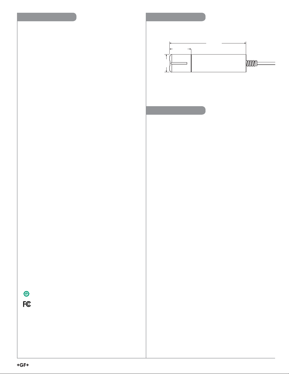
DimensionsSpecifi cations
20.3 cm
68.6 mm
(2.7 in.)
43.7 mm
(1.72 in.)
(8.0 in.)
Serial Numbers
The instrument part number, code number and serial number is
engraved on the side of the unit.
Environmental
Wetted Materials .......................ABS, Titanium, FKM
Usage life of cap ....................... 2 year from the fi rst
instrument reading
Shelf life of cap ......................... 36 months from date of
manufacture (install w/in 12 mo.
of manufacture)
Operating temperature .............0 °C to 50 °C (32 °F to 122 °F)
IP rating .................................... IP-67 with cap off, IP-68 with
cap installed
Storage conditions, cap ............ 1 °C to 60 °C (33 °F to 140 °F),
in factory container
Storage conditions, sensor: ......-5 °C to 60 °C (23 °F to 140 °F)
Warranty
Sensor ...................................... 3 years from date of
manufacture
Cap ........................................... 2 years from date of
manufacture or 2 years from
fi rst reading, whichever comes
fi rst
Standards and Approvals
CE
RoHS Compliant
China RoHS (Go to www.gfsignet.com for details)
This device complies with Part 15 of the FCC rules.
Operation is subject to the following two conditions:
(1) This device may not cause harmful interference,
and, (2) This device must accept any interference
received, including interference that may cause undesired
operation.
Signet 2610 Process Optical Dissolved Oxygen Sensor
3
Page 4

Unpacking the Sensor
1. Remove from the shipping box the GEN II DO
sensor and the cylindrical storage container
containing the sensor cap.
2. Hold the main body with one hand and with your
pother hand turn the nose cone counter clockwise
to remove the nose cone.
3. Remove the RED dust cap by gently pulling the cap
with your fi ngers.
4. Open the small cylindrical container and remove the
sensor cap.
5. Inspect the two contacts on the sensor tip for
damage.
6. Aligh the sensor cap internal fl at to the sensor tip
fl at and install.
7. Verify the cap is sitting fl ush with the sensor tip
base.
8. Reinstall the nose cone.
Sensor Cap in
Storage Container
Sensor
1
2
CAUTION: Twisting the sensor cap can permanently
damage both the cap and the sensor.
• Avoid allowing moisture, including atmospheric
humidity, inside the cap. Keep the cap in its sealed
packaging until you are ready to install it. Install
promptly. Make sure that O-ring grooves are dry
and the O-ring is not rolled or pinched inside the
cap.
• The cap's lifetime is 2 years after the fi rst reading
has been taken. Install by the date printed on the
packaging.
Calibration
Calibration is not required. The unit, as shipped from
the factory, will measure within 2% of reading for the life
of the sensor cap.
Replacing the sensor cap will keep the reading within
2% accuracy.
No
3
5
4
6
7
Yes
4
Signet 2610 Process Optical Dissolved Oxygen Sensor
Page 5

3-2610-51 to 9900 Wiring
3-2610 to Modbus Wiring
24 VDC
Regulated
Power Supply
V+
9900
3
L Inputs
S
SHLD
DATA
GND
V+
9900
Power Inputs
Red
Red
Black
V-
Shield
Red
White
Black
No connection
Brown, Blue, Green
PWR+
PWR–
LOOP+
LOOP–
DO Sensor
3-2610-51
NOTE: The S
No connection
Brown, White
3
L and Modbus connectors can be used
Red
Black
Blue
Green
Modbus
PLC
+
-
Power Supply
+
RS485
12 to 24 VDC
Regulated
–
Modbus
RS485
Programmable Logic Controller
or
Other Modbus Master
simultaneously with the 4 to 20 mA.
DO Sensor
3-2610-41
Modbus programming manual is available
on the web at www.gfsignet.com.
3-2610 to 4 to 20 mA Wiring
Red
Black
Brown
No connection
White, Blue, Green
+ In - In
PLC
OR
Programmable Logic Controller
DO Sensor
3-2610-51
NOTE: The S
+ In
3
L and Modbus
- In
Chart
Recorder
connectors can be used
simultaneously with the 4 to 20 mA.
+
-
4 to 20 mA
Input
12 to 24 VDC
Regulated
Power Supply
3-9950 Wiring
9950 S3L Inputs
Red
+
Power Supply
–
12 to 32 VDC
No connection
Brown, Blue, Green
White
Black
Shield
DO Sensor
3-2610-51
Technical Notes:
The wiring of the 3-2610-51 is non-standard:
• RED is 12 to 24 VDC
• WHITE is Data
• BLACK is VDC Ground (PWR -)
• A jumper MUST be installed between PWR- and
S3L GND.
PWR+
PWR–
Loop1+
Loop1–
Loop2+
Loop2–
FREQ
DATA
GND
CH2 CH1
FREQ
DATA
GND
DC POWER
+V
+V
PWR +
PWR –
+V
FREQ
DATA
GND
For 8900 wiring, contact factory
9900 Generation III supports 3-2610-51
direct connection. Please refer to the 9900
product manual for setup instructions.
Signet 2610 Process Optical Dissolved Oxygen Sensor
5
Page 6

Sensor Cap Replacement
Replace the Sensor Cap
The sensor cap has a 2-year life after the instrument takes its fi rst reading. Install the cap by the date printed on the package.
Replacement caps are available from Georg Fischer, part number 3-2610.394 (159 310 301).
Avoid allowing moisture, including atmospheric humidity, inside the cap. Keep the cap in its sealed package until\you are
ready to install it. Install promptly. Make sure that O-ring grooves are dry and that the O-rings are not rolled or pinched
inside the cap.
1. Pull the used sensor cap off of the sensor. DO NOT TWIST!
2. Remove the existing O-rings from the sensor.
3. Use a lint-free cloth to remove any moisture from the sensor body. NOTE: Make sure that the O-ring grooves are dry. Avoid
touching or cleaning the lens with anything other than the supplied lens wipe.
4. Use your fi nger to apply a thin layer of lubricant around the O-ring grooves. Place the O-rings on the sensor. NOTE: Do not
transfer lubricant to the lens or sensor pins.
5. Clean the lens on the sensor with the wipe provided in the kit and allow to dry thoroughly. Inspect for scratches or dirt.
6. Remove the new cap from its sealed package.
7. Align the arrow on the cap with the index mark on the sensor and press it fi rmly until it seals over the probe body. DO NOT
TWIST. Make sure that the O-rings are not pinched or rolled between the cap and sensor.
8. Replace the nose cone on the sensor.
Lightly coat with lubricant
Install 2 O-rings
Clean lens and allow to dry
Replace cap in
a dry environment
Sensor Cap Replacement Kit Contents:
• Sensor cap
• O-rings (2)
• O-ring lubricant
• Lens wipe
• Instruction sheet
Sensor Installation
The cable end of the Gen II DO sensor is internally
threaded (1¼ - 11½ NPT) and can be attached to an
externally threaded pipe.
When installed, make sure that the nose cone and
Temperature sensor are completely submerged.
2610 DO Threadded Pipe Adapter Kit
The adapter kit allows a 9900 to be installed right on the
3-2610-51 sensor assembly
pressurized piping system
to measure dissolved oxygen in a
. The kit includes a ¾" NPT closed
nipple, 1¼" NPT closed nipple and 2" male threaded pipe
adapter.
Use the 1¼" NPT closed nipple to install in a straight pipe for
submersible installation with monitoring instrumention in a panel.
Temperature
Sensor
1¼ in. NPT
3-2610.501 DO Threaded Pipe Adapter kit
Includes one (1) each:
¾ in. closed nipple
2 in. male NPT pipe adapter
1¼ in. closed nipple
6
Signet 2610 Process Optical Dissolved Oxygen Sensor
Page 7

Sensor Installation cont.
In-Line installations
Signet 9900, 9950,
or 8900 Instrument
3-9900.396 (159 001 701)
Angle Adjustment Adapter Kit
3-8052 (159 000 188)
Integral Mount Kit
3-2610.501 DO Threaded
Pipe Adapter kit
3-2610 Dissolved
Oxygen Sensor
Submersible installations
Customer supplied
threaded pipe
1¼" NPT closed nipple in the
3-2610.501 DO Threaded
Pipe Adapter kit
OR
Standard
GF pipes
and tees,
50.8 mm
(2 in.)
minimum
Adapters, Saddles and Tees
GF Signet has a line of tees and saddle assemblies in PVC
and CPVC for pipes ranging 2 inch to 8 inches, to allow in-line
measuring of dissolved oxygen.
3-2610 Dissolved
Oxygen Sensor
Rail Mount Adapter and
extension pipes
Float
Assembly
See Signet Submersion Kit Brochure
(3-0000.707) at gfsignet.com/Resource
Center for extension pipe information
Signet 2610 Process Optical Dissolved Oxygen Sensor
7
Page 8

Ordering Information
2610 Optical DO Sensor
Mfr. Part No Code Description
3-2610-51 159 001 849 Optical DO Sensor (0-20 ppm) with S
Accessories and Replacement Parts
Mfr. Part No Code Description
3-2610.392 159 310 122 Replacement Optical Dissolved Oxygen Sensor Cap (0 to 20 ppm) for 3-2610-31 and 3-2610-41DO Sensors
3-2610.394 159 310 301 Replacement Optical Dissolved Oxygen Sensor cap (0 to 20 ppm) for Gen II 3-2610-51 DO Sensor
3-2610.501 159 500 413 DO Threaded Pipe Adapter kit, includes one each: 2 in. male NPT pipe adapter, 1¼ in. closed nipple, ¾ in.
closed nipple.
3-2610.312 Special* Rail Mount Adapter and extension pipes for Dissolved Oxygen, pH, ORP, and Conductivity sensors
3-2610.FLT Special* Float assembly for Dissolved Oxygen, pH, ORP, and Conductivity sensors
3-2610.81950 Special* DO Sensor Air-Blast
3-2610.81300 Special* DO sensor Anti-fouling Guard
3-2610.100 Special* 2 inch Tee Assembly, PVC
3-2610.101-01 Special* 3 in. Saddle Assembly
3-2610.101-02 Special* 4 in. Saddle Assembly
3-2610.101-03 Special* 6 in. Saddle Assembly
3-2610.101-04 Special* 8 in. Saddle Assembly
3
L, Modbus, and 4 to 20 mA output
* Special only. Contact GF Signet for more information.
Rail mount adapter, extension pipes and fl oat assembly for Dissolved Oxygen, pH, ORP, and Conductivity sensors.
The rail mount adapter has a dual pivot point which allows any GF Signet sensor pipe assembly
(sold separately) to move, both vertically and horizontally, over an open channel, tank, or process weir. Once the sensor
is brought out of the solution vertically, a safety pin locks the sensor into position, and the horizontal axis is used to swing
the sensor assembly safely outside the process area for maintenance and cleaning. Manufactured out of SS for corrosion
resistance.
The GF Signet fl oat assembly allows any Signet electrode to be placed into a process at a specifi c depth.
The fl oat comes complete with a 1 inch male NPT nipple assembly, which threads into a customer supplied piping system.
Call the factory for ISO piping requirements.
DO Sensor Air-Blast (3-2610-81950)
Attach an air blast adapter to the DO sensor and a 20 psi air source using a ¼” OD tube, this allows the sensor to be cleaned.
A 60 second blast every four hours extends the length of time between overall maintenance and cleaning. Wetted material:
Acetal, SS set screw
DO Anti Fouling Guard (3-2610-81300)
Reduces biological fouling while improving measurement accuracy and extends the length of time between cleaning of
the sensor. Simply attach the copper guard onto the front of the sensor. It is recommended the guard be replaced every
6 months. Wetted material: Delrin, high purity copper
Georg Fischer Signet LLC, 3401 Aero Jet Avenue, El Monte, CA 91731-2882 U.S.A. • Tel. (626) 571-2770 • Fax (626) 573-2057
For Worldwide Sales and Service, visit our website: www.gfsignet.com • or call (in the U.S.): (800) 854-4090
For the most up-to-date information, please refer to our website at www.gfsignet.com
3-2610.090 Rev. 3 04/18 English © Georg Fischer Signet LLC 2018
 Loading...