

Page 1
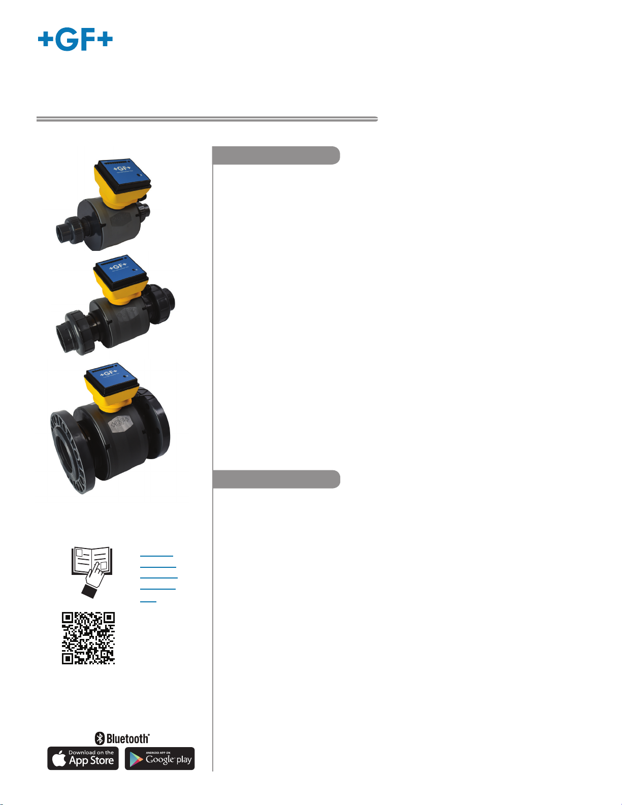
Signet 2580 FlowtraMag® Meter
*3-2580.090*
3-2580.090 Rev 3 04/20
Description
English
Operating Instructions
The GF Signet 2580 FlowtraMag is a full-bore plastic PVC in line style magnetic owmeter.
The PVC body with titanium or Hastelloy
three times lighter in weight compared to traditional metal magmeters on the market. It is
designed for high accuracy ow measurement in short pipe runs, making it an ideal solution
for industrial applications where performance and ease of use are important.
The FlowtraMag is available in pipe sizes of DN25 (1 in.), DN50 (2 in.) and DN100 (4 in.),
optimized for performance in short pipe runs often associated with nal euent lines, well
heads and water treatment skids.
Features include:
• No moving parts
• No pressure drop
• Lighter in weight compared to traditional metal magmeters
• Reduced straight run requirements, ideal for nal euent lines, well heads and skids
• Factory calibrated with certicate (±1% of reading accuracy)
• Partially lled pipe detection status indicator
• Visual LED indicators make sensor status clear and easy to read
• Reverse ow direction congurable with 0252 Conguration Tool or GF Cong Tool
Bluetooth
• One device with three dierent outputs: eld selectable Frequency or Digital (S³L),
and analog 4 to 20 mA
• On-the-y conguration with GF Cong Tool Bluetooth
• Bluetooth
®
App
®
4.2 capable, support iOS and Android for simple user conguration
®
C electrodes has no moving parts, and is two to
®
App
• English
• Deutsch
• Français
• Español
• 中文
Table of Contents
Warranty Information ...............................................................................2
Product Registration ................................................................................2
Safety Information ...................................................................................2
Chemical Compatibility ............................................................................2
Temperature-Pressure Graph .................................................................. 2
Specications ..........................................................................................3
Sensor Dimensions .................................................................................4
Sensor Location.......................................................................................5
Sensor Mounting Angle ...........................................................................5
Sensor Pipe Installation ...........................................................................6
Wiring Conguration ................................................................................7
Default Congurations .............................................................................8
Wiring ......................................................................................................9
App Conguration - Setup .....................................................................12
App Conguration - Monitor and Real Time Log ...................................13
App Conguration - Files .......................................................................14
App Conguration - Sensor Setup .........................................................14
Change Language .................................................................................16
Calibration .............................................................................................16
Customization and Performance Settings .............................................16
Averaging and Sensitivity Settings ........................................................17
LED Status Indicators ............................................................................17
Conguration - 0252 Conguration Tool ................................................ 18
Troubleshooting .....................................................................................21
Ordering Information..............................................................................24
U.S. and International Patents Pending
Page 2
Chemical CompatibilityWarranty Information
Hand tighten only!
Refer to your local Georg Fischer Sales oce for the most
current warranty statement.
All warranty and non-warranty repairs being returned must
include a fully completed Service Form and goods must be
returned to your local GF Sales oce or distributor.
Product returned without a Service Form may not be
warranty replaced or repaired.
Signet products with limited shelf-life (e.g. pH, ORP, chlorine
electrodes, calibration solutions; e.g. pH buers, turbidity
standards or other solutions) are warranted out of box but not
warranted against any damage, due to process or application
failures (e.g. high temperature,
mishandling (e.g. broken glass,
chemical poisoning, dry-out) or
damaged membrane, freezing
and/or extreme temperatures).
Product Registration
Thank you for purchasing the Signet line of Georg Fischer
measurement products.
If you would like to register your product(s), you can now
register online in one of the following ways:
• Visit our website www.gfsignet.com.
Under Service and Support click on
Product Registration Form
• If this is a pdf manual (digital copy), click here
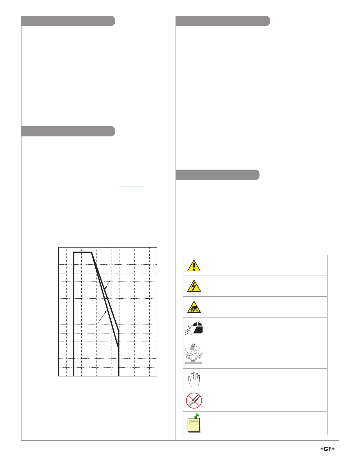
Operating Pressure/Temperature Graph
(bar)(psi)
150
10.3
140
9.7
130
9.0
120
8.3
110
7.6
100
6.9
90
6.2
80
5.5
70
4.8
60
4.1
50
3.4
40
2.8
30
2.1
20
1.4
10
0.7
0
-20 0 20 40 60 80 100
°F°C-4 32 68 104 140 176 212
DN100
(4 in.)
DN25 (1 in.),
DN50 (2 in.)
@ 3.5 bar
(51 psi)
@ 2.27 bar
(33 psi)
Georg Fischer Signet products are manufactured in a variety of
wetted materials to suit various liquids and chemicals.
All plastic materials including typical piping types (PVC) are more
or less permeable to contained media, such as water or volatile
substances, including some acids. This eect is not related to
porosity, but purely a matter of gas diusion through the plastic.
If the plastic material is compatible with the medium according
to the application guidelines, the permeation will not damage
the plastic itself. However, if the plastic encloses other sensitive
components, as is the case with GF Signet FlowtraMag meter,
these may be aected or damaged by the media diusing
through the plastic body.
Unit is factory shipped congured to measure water.
Safety Information
1. Depressurize and vent system prior to installation or removal.
2. Conrm chemical compatibility before use.
3. DO NOT exceed maximum temperature or pressure specs.
4. ALWAYS wear safety goggles or face shield during
installation and/or service.
5. DO NOT alter product construction.
6. If this equipment is used in a manner not specied by the
manufacturer, the protection provided by the equipment may
be impaired
7. This device is not approved for use or installation in
hazardous locations.
Caution / Warning / Danger
Indicates a potential hazard. Failure to follow all warnings
may lead to equipment damage, injury, or death
Electrocution Danger
Alerts user to risk of
electrocution.
Electrostatic Discharge (ESD)
Alerts user to risk of potential damage to product by ESD.
Personal Protective Equipment (PPE)
Always utilize the most appropriate PPE during
installation and service of Signet products.
Pressurized System Warning
Sensor may be under pressure, take caution to vent
system prior to installation or removal. Failure to do so
may result in equipment damage and/or serious injury.
Hand Tighten Only
Overtightening may permanently damage product threads
and lead to failure. (union nut only)
Do Not Use Tools
Use of tool(s) may damage product beyond repair and
potentially void product warranty. (union nut only)
potential of injury or death via
.
2
Signet 2580 FlowtraMag Meter
Note / Technical Notes
Highlights additional information or detailed procedure.
Page 3
Specications
General
Pipe Size Range ..................... DN25 (1 in.), DN50 (2 in.)
DN100 (4 in.)
Flow Range - Titanium or Hastelloy
C
Minimum .................................. 0.02 m/s (0.07 ft/s)
Maximum ................................. 10 m/s (33 ft/s)
DN25 (1 in.) ............................. 0.53 to 266.35 L/min
(0.14 to 70.36 gal/min)
DN50 (2 in.) ............................. 2.23 to 1112.60 L/min
(0.59 to 293.92 gal/min)
DN100 (4 in.) ........................... 8.72 to 4357.83 L/min
(2.30 to 1151.22 gal/min)
Repeatability ........................... ± 0.5% of reading @ 25 °C (77 °F)
Accuracy ................................. ± 1% ± 0.01 m/s (0.033 ft/s)
(reference condition 50 µS/cm and
water based)
Minimum Conductivity ............. 20 µS/cm - water based
Suspended Solids ................... 5%
Power Cable Wire ................... 7.6 m (25 ft) 2-conductor shielded
Output Cable Wire .................. 7.6 m (25 ft) 5-conductor shielded
• May be extended up to 305 m (1000 ft), special order only
Wetted Materials
Flow Tube Body ...................... PVC
Electrode ................................. Titanium, grade 2 or
Hastelloy C
O-rings ..................................... FKM
-276
Electrical
Power Requirements
DC Power
(Functional Rating) .................. 24 VDC, max 24W (12 to 32 VDC)
Reverse Polarity Protected ..... Up to 35 VDC
Over-Voltage Max. Rating ....... 35 VDC
Please use a power supply that has been IEC 60950/61010/60601
Certied and will not be used outside of its electrical ratings and
matches the environmental conditions of the ow meter.
Current Output
Passive (low power) 4 to 20 mA per ANSI-ISA 50.00.01 class H
Active Output ........................... 4 to 20 mA
Passive Loop Voltage .............12 to 32 VDC
Loop Accuracy......................... ± 32 µA (25 °C @ 24 VDC)
Loop Resolution ...................... 5 µA
Loop Span ............................... 3.8 mA to 21 mA
Error condition ......................... None, 3.6 mA or 22 mA
Max. Cable .............................. 300 m (1000 ft)
Max. Loop Resistance ............ 600 Ω @ 24 VDC
Compatible with PLC, PC or similar equipment
Frequency Output
Frequency ............................... 5 to 24 VDC, 50 mA max.
Frequency Range ................... 0 to 1500 Hz
Max. Pull-up Voltage ............... 30 VDC, 10k pull-up recommended
Max. Cable .............................. 300 m (1000 ft)
Compatible with Signet 8900, 9900, 9950, and
0486 Probus Concentrator
Digital (S3L) Output
Digital (S3L) ............................. 4.5 to 5.5 VDC
Serial ASCII, TTL level 9600 bps
Compatible with Signet 8900, 9900, 9950 and
0486 Probus Concentrator
Max. Cable Length .................. Application dependent
Hastelloy® is a registered trademark of Haynes International.
Sensor Conguration
GF Cong Tool Bluetooth® App
2.4 GHz RF Transceiver Compatible with Bluetooth®
Low Energy (BLE) 4.2 Specication
GF Cong Tool App available in iOS and Android
App Stores
0252 Conguration Tool
Environmental Requirements
Enclosure ................................ NEMA 4X / IP65
Relative Humidity .................... 0 to 95% (non-condensing)
Altitude .................................... 4,000 m (13,123 ft)
Storage Temperature .............. -10 °C to 60 °C (14 °F to 140 °F)
Operating Temperature
Ambient ............................... -10 °C to 60 °C (14 °F to 140 °F)
Media .................................. 0 °C to 60 °C (32 °F to 140 °F)
UL environmental Rating .....UL 50, Type 6P Storage
Maximum Operating
Pressure .................................. 10 bar @ 23 °C (145 psi @ 73 °F)
DN25 (1in.) and DN50 (2in.) .... 3.5 bar @ 60 °C (51 psi @ 140 °F)
DN100 (4in.) ............................ 2.27 bar @ 60 °C (33 psi @ 140 °F)
Shipping Weights - Titanium or
Hastelloy C
DN25 (1 in.) ............................. 3.4 kg (7.5 lbs)
DN50 (2 in.) ............................. 4.5 kg (9.9 lbs)
DN100 (4 in.) ........................... 8.3 kg (18.3 lbs)
Sensor Weights - Titanium or
Hastelloy C
DN25 (1 in.) .............................. 2.7 kg (5.9 lbs)
DN50 (2 in.) .............................. 3.7 kg (8.1 lbs)
DN100 (4 in.) ............................ 6.26 kg (13.9 lbs) - (excludes mounting
hardware)
Standards and Approvals
CE
UL, CUL Recognized Component
NSF (Titanium only, does not include Flange gaskets)
RoHS compliant
Manufactured under ISO 9001 for Quality, ISO 14001
for Environmental Management and OHSAS 18001 for
Occupational Health and Safety.
China RoHS (visit gfsignet.com for details)
Declaration of Conformity according to FCC Part 15
This device complies with Part 15 of the FCC rules.
Operation is subject to the following two conditions:
(1) This device may not cause harmful interference, and,
(2) This device must accept any interference received, including
interference that may cause undesired operation.
The Bluetooth® word mark and logos are registered trademarks owned
by Bluetooth SIG,Inc. and any use of such marks by Georg Fischer is
under license. Other trademarks and trade names are those of their
respective owners.
Signet 2580 FlowtraMag Meter
3
Page 4
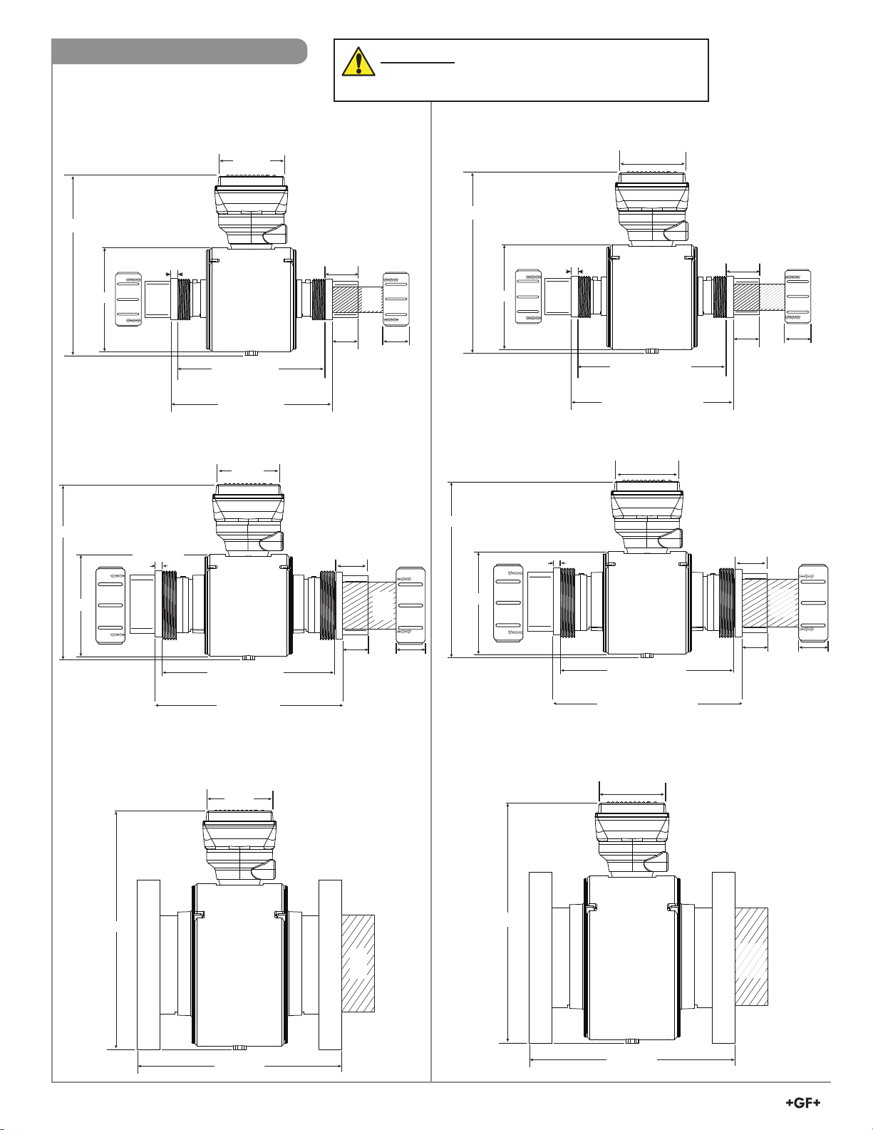
Sensor Dimensions
3.90 in.
9.42 in.
± 1.58 mm (1/16 in.)
5.56 in.
Pipe
2 in.
ID
9.82 in.
1.50 in.1.51 in.
x 2
1.65 in.
10.18 ± 0.10 in
Pipe cutout dimension
0.38 in. x 2
± 0.125 in
3.90 in.
9.42 in.
± 1.58 mm (1/16 in.)
5.56 in.
Pipe
1 in.
ID
Pipe
2 in.
ID
9.82 in.
1.25 in.
1.13 in.
x 2
1.41 in.
1.50 in.1.51 in.
x 2
1.65 in.
10.18 ± 0.10 in
Pipe cutout dimension
0.38 in. x 2
99.0 mm
239.26 mm
± 1.58 mm (1/16 in.)
141.2 mm
Pipe
DN25
ID
Pipe
DN50
ID
249.4 mm
31.8 mm
28.7 mm
x 2
35.8 mm
38.1 mm38.4 mm
x 2
41 mm
245.3 mm ± 1.8 mm
Pipe cutout dimension
9.7 mm x 2
99.0 mm
239.26 mm
± 1.58 mm (1/16 in.)
141.2 mm
Pipe
DN50
ID
249.4 mm
38.1 mm38.4 mm
x 2
41 mm
245.3 mm ± 1.8 mm
Pipe cutout dimension
9.7 mm x 2
WARNING!
ASTM and Metric pipe cutout dimensions are dierent.
1 in.
Union ends and union nuts shown
3.90 in.
9.82 in.
0.28 in. x 2
5.56 in.
7.86 in.
± 1.58 mm (1/16 in.)
8.42 ± 0.10 in
Pipe cutout dimension
2 in.
Union ends and union nuts shown
3.90 in.
9.82 in.
0.38 in. x 2
5.56 in.
9.42 in.
Pipe cutout dimension
± 1.58 mm (1/16 in.)
10.18 ± 0.10 in
4 in.
Flange bolt kits and gaskets not shown (Sold separately)
3.90 in.
1.41 in.
Pipe
1 in.
1.13 in.
x 2
1.65 in.
1.51 in.
x 2
ID
1.25 in.
Pipe
2 in.
ID
1.50 in.
DN25
Union ends and union nuts shown
99.0 mm
249.4 mm
35.8 mm
28.7 mm
x 2
141.2 mm
7.1 mm x 2
199.64 mm
± 1.58 mm (1/16 in.)
203.6 mm ± 1.8 mm
Pipe cutout dimension
DN50
Union ends and union nuts shown
99.0 mm
249.4 mm
41 mm
38.4 mm
141.2 mm
9.7 mm x 2
239.26 mm
± 1.58 mm (1/16 in.)
245.3 mm ± 1.8 mm
Pipe cutout dimension
DN100
Flange bolt kits and gaskets not shown (Sold separately)
99.0 mm
DN25
x 2
Pipe
ID
Pipe
DN50
ID
31.8 mm
38.1 mm
327.7 mm
276.86 mm
± 3.2 mm
Pipe
DN100
ID
Pipe
4 in.
ID
12.90 in.
10.90 in.
4
Signet 2580 FlowtraMag Meter
Page 5
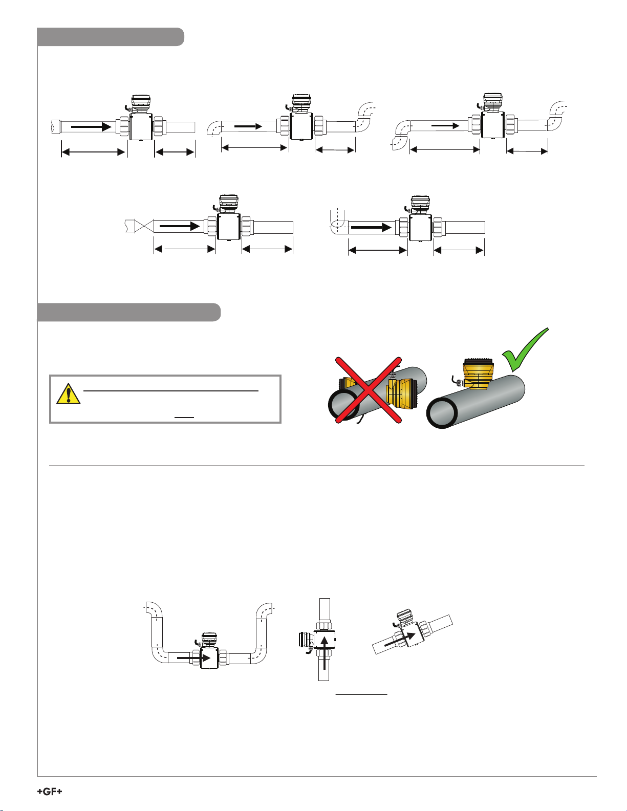
Sensor Location
3 x I.D.
2 x I.D.
2 x 90° Elbow
3 x I.D. 2 x I.D.
90° Elbow
3 x I.D. 2 x I.D.
2 x 90° Elbow
3 dimensions
3 x I.D. 2 x I.D.
The 2580 FlowtraMag requires a minimum of 3x ID upstream and 2 x ID downstream of the sensor for best performance.
Reducer
3 x I.D. 2 x I.D.
Pump/Valve
3 x I.D. 2 x I.D.
90° Elbow
3 x I.D. 2 x I.D.
Sensor Mounting Angle
Horizontal Pipe Runs
GF recommends installing the sensor electronics at the
12 o'clock position.
DO NOT HANDLE BY THE SENSOR!
Always handle FlowtraMag Meters by the
union nuts or anges, NOT the sensor head.
2 x 90° Elbow
3 dimensions
3 x I.D. 2 x I.D.
2 x 90° Elbow
3 x I.D.
2 x I.D.
Vertical Pipe Runs
To ensure pipe is owing full with some back pressure, it is highly recommended that the uid ows upward.
Gravity and Discharge Lines
It is recommended to install a u-trap to ensure the pipe remains full at all times, and to minimize air bubbles.
A vacuum breaker may be required downstream of the FlowtraMag to ensure pipe doesn't drain and ll with air.
OKRecommended OK
Vertical flow is OK IF the
pipe remains FULL
at all times.
Signet 2580 FlowtraMag Meter
5
Page 6
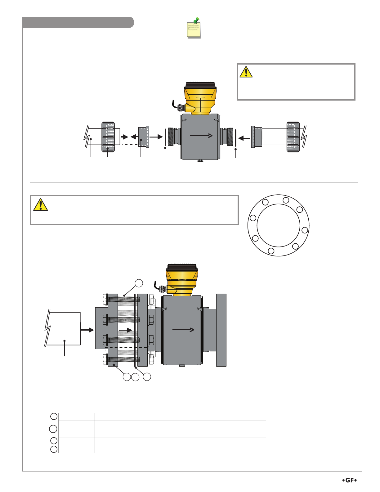
O-ring
Pipe Union
Nut
Union
End
Flow
O-ring
Nut
End
Sensor Pipe Installation
1. Choose a mounting location that satises
the requirements.
2. Select appropriate (Metric or ASTM) union
end for installation
3. Install sensor with ow arrow pointing in
the direction of ow.
Note: Gland ttings should point upstream
of ow.
Application Tip: For Metric pipe
installation, change union end to Metric.
2580 FlowtraMag DN25 (1 in.)
2580 FlowtraMag DN50 (2 in.)
Union Ends
Hand Tighten Only!
Flow
Pipe Union
Union
O-ring
2580 FlowtraMag DN100 (4 in.) Bolts
DO NOT OVER TORQUE!
Recommended bolt torque for the DN100 (4") ange of 27-41 Nm, (20 to 30 ft-lbs)
Tighten bolts by rst assembling and hand tightening the nuts to position the
gasket in place. Then tighten the bolts in a diagonal pattern 50% the recommended
torque, then 100% of recommended torque.
2
Flow
O-ring
5
3
Tightening
7
Pattern
2
1
8
4
6
Pipe
1a
1
Part No. Description
1
854-040 DN100 Flange Adapter, PVC-U Metric
721790114 DN100 Flange Adapter, PVC-U Metric (with backing ange, below)
1a
721700014 DN100 Backing Flange, PVC-U Metric
2
37Z000069 Van Stone Flange Bolt Kit, 8 hole
749440714 DN100 Prole Gaskets
3
Sold separately, quantity 2 required. See Ordering Information.
6
Signet 2580 FlowtraMag Meter
3
Page 7
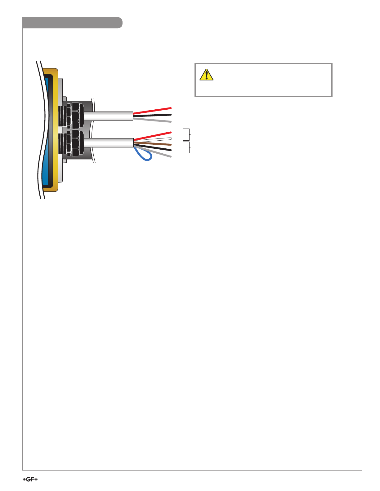
Wiring Conguration
When using the 2580 FlowtraMag with frequency or Digital (S3L), all of the connections from the 2580 FlowtraMag
to external equipment (PLC, Datalogger, Chart Recorder, Flow meter, etc.) are made using the red and white wires.
See wiring diagrams for further details.
3-2580
DO NOT REMOVE WIRING!
Damaging or removing the power or
output cables will void warranty.
Power cable
Output cable
Blue used for
GF Config App password
reset only
Red
Black
Shield
Red
White
Brown
Black
Shield
S3L / Frequency
4 to 20 mA
Electromagnetic Compatibility (EMC) Recommendations
Complex instrumentation systems such as the 2580 FlowtraMag and the associated devices may face challenges involving
Electromagnetic Interference (EMI). EMI interference may be coupled to the system via cables (conducted interference) or
broadcast via electrical radiation (radiated interference).
Radiated interference may be mitigated by relocating the source or increasing the distance from the source. Metal shielding may be
used.
Conducted interference can be mitigated by careful wiring practices. Because EMI may follow multiple paths, it will be necessary to
observe the eectiveness of various grounding options.
2580 FlowtraMag Power Cable
• In electrically noisy environments, connect the power cable shield (drain) wire to a clean low impedance earth ground.
• If there is a single power supply for all 2580 FlowtraMag system components (Instruments, PLCs and VFDs), route signal
wiring directly to the instruments. Do not use ground points common to other wiring. Avoid creating ground loops.
• If separate power supplies are used, connect all power grounds to a common low impedance ground.
2580 FlowtraMag Output Cable
• In electrically noisy environments, connecting the Signal Output cable shield (drain) wire to a clean low impedance earth
ground may help reduce signal noise and preserve communication. Observe the dierence between connecting or not
connecting the shield. Avoid creating ground loops.
Frequency/S3L Output
- The S3L/Frequency cable shares the ground with the 2580 FlowtraMag Power Supply. Use a common DC power supply
for the 2580 FlowtraMag and the ow instrument.
4 to 20 mA Output
- If the 4 to 20 mA is used to control a highly inductive load such as a Variable Freq Drive or a DC motor, use separate DC
power supplies for the 2580 FlowtraMag and the 4 to 20 mA device, active mode should be used.
- In Passive mode the 2580 FlowtraMag loop output cable shares the ground with the 2580 FlowtraMag Power Supply.
Use the same DC power supply for the 2580 FlowtraMag and the 4 to 20 mA device.
- In Active mode the 2580 FlowtraMag loop output cable is isolated from the 2580 FlowtraMag Power Supply. The 4 to 20
mA device can use a dierent Power Supply.
Signet 2580 FlowtraMag Meter
7
Page 8
Wiring Conguration Continued
Recommended:
The directional arrow should be pointed
DOWNSTREAM for correct operation. If the 2580
FlowtraMag is installed on a vertical pipe, the cable
ports should be turned to point downward. This will
prevent condensation from being channeled into
the enclosure.
Application Tip:
If your ow is in the reverse direction, it is possible to set
up reverse ow via the GF Signet 0252 Conguration
Tool or GF Cong Tool App.
Default Congurations
DN25 (1 in.) DN50 (2 in.) DN100 (4 in.)
Units GPM GPM GPM
Totalizer Units Gallons Gallons Gallons
Temperature Units °C °C °C
K-Factor Values 852.716 pulse/gal 204.139 pulse/gal 52.1188 pulse/gal
Averaging Low Low Low
Sensitivity 3.5182 14.696 57.561
Low Flow Cuto 0.1407 0.5878 2.3024
4 mA Setpoint 0 0 0
20 mA Setpoint 70.363 293.92 1151.2
Error Current 22 22 22
Passive/Active Passive Passive Passive
S3L/Freq Freq Freq Freq
NOTE:
Temperature Units on
Bluetooth
®
app will not be
available for Hastelloy C.
(Function will display: nan °C.)
8
Signet 2580 FlowtraMag Meter
Page 9

Wiring
Black
Shield (EMC enhancement)
Shield
2580
Shield
2580
Power cable
–
Red
+
DO NOT REMOVE Seal!
Warranty void if seal is
broken or removed.
Wiring with 4 to 20 mA Loop Output
24 VDC @ 1A min.
24 VDC @ 1A min.
Power Supply
WARRANTY
VOID IF
REMOVED
–
Power Supply
+
WARRANTY
VOID IF
REMOVED
Black
Red
CAUTION!
Turn o Power before Wiring.
Power cable
Choose Passive or Active
in Bluetooth App
Wiring with Frequency Output
Compatible with all POWERED Signet Flow Instruments
• When choosing Frequency in the
Bluetooth® App, the 2580 FlowtraMag
outputs an open collector frequency signal
that can be connected to any powered
Signet ow meter (models 8900, 9900,
9900-1BC, 9950).
• 24 VDC power at 1 amp should always be
connected.
NOTE: The frequency output will be
displayed as positive ow
regardless of the ow direction.
24 VDC @ 1A min.
Power Supply
4 to 20 mA + (Brown)
4 to 20 mA - (Black)
–
+
Data (Red)
Ground - (White)
Black
Red
Shield (EMC enhancement)
2580
Output cable
Blue not used
Red
White
Not used
Power cable
Shield (EMC enhancement)
2580
Output cable
Choose Frequency in
Bluetooth
®
App
Blue not used
Brown
Black
Not used
Signet 2580 FlowtraMag Meter
9
Page 10

Wiring with Frequency Other Manufacturer's Equipment
–
Choose Frequency in
Bluetooth
Shield (EMC enhancement)
When using the 2580
FlowtraMag in a system
with other manufacturer's
equipment, a 10 KΩ pull-up
5 - 30 VDC
Power Supply
+
resistor (not supplied) may
be required to power the
open collector output.
Other MFG
Equipment
Freq In
®
App
GND
10KΩ
Data (Red)
Ground - (White)
Wiring with Digital (S3L) Output
2580 FlowtraMag Wiring to Signet 8900 - Two digital (S3L) inputs
8900
2580
Output cable
Blue not used
Brown
Black
Not used
Frequency
Input
1
Frequency
Input 2
OR
3
L
S
Input
2
3
L
S
Input
1
2580 FlowtraMag Wiring to Signet 8900 - One digital (S3L) input and one Frequency input
8900
Frequency
Input
1
Frequency
Input 2
OR
3
L
S
Input
2
3
L
S
Input
1
10
Signet 2580 FlowtraMag Meter
+5VDC (Black)
Freq. Input (Red)
GND (Shield)
+5VDC (Black)
Freq. Input 2 (Red)
3
S L (Red)
GND (White/Shield)
+5VDC (Black)
3
S L (Red)
GND (White/Shield)
Analog Output 1
(if applicable)
Analog Output 2
(if applicable)
+5VDC (Black)
Freq. Input (Red)
GND (Shield)
+5VDC (Black)
Freq. Input 2 (Red)
3
S L (Red)
GND (White/Shield)
+5VDC (Black)
3
S L (Red)
GND (White/Shield)
Analog Output 1
(if applicable)
Analog Output 2
(if applicable)
1
2
3
4
5
3
6
7
8
3
9
10
11
+
-
12
13
+
-
14
1
2
3
4
5
3
6
7
8
3
9
10
11
+
-
12
13
+
-
14
SENSOR INPUTS
OUT 2 OUT 1
SENSOR INPUTS
OUT 2 OUT 1
S3L 1
OR
S3L 2
Frequency 1
OR
S3L 2
GF Cong Tool App set to S3L
Data (Red)
Ground (White)
Brown
Black
Shield
2580
Output cable
Blue not used
Not used
GF Cong Tool App set to
3
L on Channel 2
S
Data (Red)
Ground (White)
Brown
Black
Shield
2580
Output cable
Blue not used
Not used
Page 11

Wiring with Digital (S3L) Output
+V
FREQ
DATA
GND
9950
No connection
No connection
9950
Frequency
+V
FREQ
DATA
GND
+V
FREQ
DATA
GND
Loop1+
Loop1–
Loop2+
Loop2–
PWR+
PWR–
CH2 CH1
DC POWER
X
No connection
X
No connection
Shield
2580
Output cable
Black
Brown
Shield
Blue not used
Not used
Ground (White)
Frequency (Red)
9950
Shield
Digital (S3L) Output (Compatible with 8900 Multi-Parameter Controller, 9900 and 9950 Transmitter)
• To select S3L, use Bluetooth® App.
• 24 VDC power at a minimum of 1 amp is always be connected to the 2580 FlowtraMag.
• The 8900 will display 0 (Zero) ow rate during periods of reverse ow.
The 9900 and 9950 will display negative numbers to indicate reverse ow.
• The maximum cable length from the 2580 FlowtraMag to the 8900 or 9900 depends on the 8900 or 9900
conguration. Refer to the 8900, 9900 or 9950 manual for complete information.
2580 FlowtraMag Wiring to Signet 9900
Data (Red)
Ground (White)
2580
Output cable
S3L/Freq
9900
Transmitter
24 VDC @ 1A min.
9900 S3L
Terminal
DATA
GNDV+SHLD
9900
Power
Input
PWR+
PWR–
LOOP+
LOOP–
Power Supply
–
+
2580 FlowtraMag Wiring to Signet 9950
Digital (S3L)
DC POWER
+V
X
FREQ
X
DATA
GND
PWR+
PWR–
Loop1+
Loop1–
Loop2+
Loop2–
FREQ
DATA
GND
CH2 CH1
FREQ
DATA
GND
+V
+V
GF Cong Tool App set to S
Data (Red)
Ground (White)
Brown
Black
Output cable
Blue not used
Not used
Refer to the 0486 Probus Concentrator manual for
Frequency wiring and programing instructions.
Black
Red
2580
No connection
No connection
X
X
+V
FREQ
DATA
GND
Brown
Black
Shield
3
L
Frequency
DC POWER
PWR+
PWR–
Loop1+
Loop1–
Loop2+
Loop2–
+V
FREQ
DATA
GND
+V
CH2 CH1
FREQ
DATA
GND
Blue not used
Not used
GF Cong Tool App
set to S3L
2580
Power cable
Shield (EMC enhancement)
Frequency (Red)
Ground (White)
Blue not used
Brown
Black
Signet 2580 FlowtraMag Meter
2580
Output cable
Not used
11
Page 12

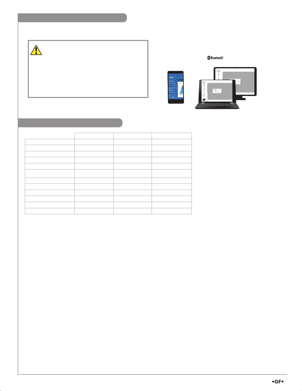
App Conguration - App Set Up
Bluetooth
Search for GF Conguration Tool in the App store. Download the GF Cong Tool.
1. Press GET. App will install on phone or other wireless device.
2. Return to home screen and look for App icon, click the blue GF Cong Tool icon
3. Continue to Sensor Setup Section (next page)
®
App Setup Steps - iOS version
Config Tool
Bluetooth® App Setup Steps - Android version
Download the GF Conguration Tool App by scanning the QR code or searching
in Google Play directly.
1. When prompted press Install
2. Return to home screen and look for App icon, click the blue GF Cong Tool icon
3. Continue to Sensor Setup section (next page.)
Config Tool
12
Signet 2580 FlowtraMag Meter
Page 13

App Conguration - Sensor Setup
When the 2580 FlowtraMag is in operation, when in close proximity to the 2580 FlowtraMag (less than 20 ft), open the
GF Cong Tool App to begin a search nearby devices and go thru the pairing process. Click on connect next to device
you are pairing to.
Config Tool
1. Pair the device by entering the device
Code/Pin.
The default Passkey is the last 6 digits of
the product serial number.
2. Click Pair/OK
3. Make any adjustments to the 2580
FlowtraMag, if necessary, by tapping the
Hamburger Menu (menu list) or Gear
(edit settings).
Hamburger
(Menu)
iOS Android
Code/Pin
Gear
(Settings)
(Version 8
or newer)
Note:
If the GF Cong Tool password has been lost or forgotten, connect
blue wire to white wire while unit is powered (for 2 to 5 seconds.)
Password will reset to factory original (last 6 digits of serial number.)
(example shows Menu)
App Conguration - Monitor and Real Time Log
Monitoring ow and temperature Real Time Log while connected to mobile / tablet device, set 1 sec or more increments
Note:
The logging screen only logs current
screen view in real-time when
connected to the app.
NOTE:
Temperature Units on Bluetooth® app will
not be available for Hastelloy C.
(Function will display: nan °C.)
Signet 2580 FlowtraMag Meter
13
Page 14

App Conguration - Files
Share and/or Save les
Naming les
To delete saved les, slide to
the right and click trash can
Create lename
The le will be saved at mobile/
tablet device under the Saved
Log Files
Then les can be sent by Email
with .csv le format
App Conguration - Sensor Setup
READ WRITE SAVE LOAD
Read Loads the data from the connected device (sensor or transmitter) and updates the software’s display.
NOTE: This will overwrite any changes made in the GF Cong Tool App since the last Write.
Write Applies the data entered in the GF Cong Tool App to the connected device. Once you have entered the desired setting
changes in the software screens, press Write to load your new settings onto the connected device.
Save Stores the entire GF Cong Tool App settings conguration, as currently displayed in the application, to your mobile device.
(You will be asked to provide a conguration le name)
Load Loads a default conguration le from the factory.
Opens a previously saved settings conguration le. See Save function above.
NOTE: The le must be a GF Cong Tool App settings conguration le.
The software will verify whether the user-selected le is the correct type.
There are conguration les available for specic body sizes containing default values from the factory.
Carefully review the Device Tag and Passkey conguration in the Information screen.
Device Tag identies the sensor you are connecting to. Device Tag maximum length 20 characters.
Device Passkey is needed for connecting to the sensor. Device Passkey is a 6 digit number.
14
Signet 2580 FlowtraMag Meter
Page 15

App Conguration - Sensor Setup Continued
Application Setup
To set Averaging, Sensitivity, Low Flow Cut O,
Position of Flow, Flow Units, and Totalizer Unit,
Loop
Set 4 mA, 20 mA, Error condition of the current
output alarm (3.6 or 22 mA), adjust your 4 to 20 mA
setting and select output mode.
Loop adjustment is a live update.
Information
Sensor information, Permanent
Totalizer, and Resettable Totalizer.
Calibration
Custom Calibration of
Rate, Volumetric, Zero
Flow Calibration.
You must press WRITE to
save your changes to
Then press DONE or press on GF logo to
get back to re-connect screen.
the sensor.
Otherwise it saves to your phone only.
To switch between S3L and Frequency and/or 4 to 20 Active or Passive, use the GF Cong Tool App. On the loop
screen, use the drop down to select S3L or Freq and/or Active or Passive 4 to 20 mA. Press WRITE after making
selection.
If the GF Cong Tool password has been lost or forgotten, connect blue wire to white wire of the sensor output cable
while unit is powered (for 2 to 5 seconds.) Disconnect blue wire from white wire after 5 seconds. Password will reset
to factory original (last 6 digits of serial number.)
To delete saved 2580 FlowtraMag in iOS: Swipe right and select the trash can icon.
To delete saved 2580 FlowtraMag in Android: Swipe right, "Are you sure you want to delete this device?" , choose
Yes or No.
Technical Note
The totalizer in the 2580 FlowtraMag is independent from the totalizer in the 9900/9950 transmitters. If the
totalizer is reset on the 2580 FlowtraMag, it does not reset the totalizer on the 9900 or 9950.
Signet 2580 FlowtraMag Meter
15
Page 16

3-0252
Shield
Change Language
Currently English and Chinese are available in the App.
Android
When you select your language of choice, it automatically
changes. No other steps are needed.
Close App
iOS device with home button
Double click the home button. Find the minimized app and swipe up to close the app to clear the App Cache.
iOS device without home button
Swipe up from the bottom. Find the minimized App and swipe up to close the app to clear the App Cache.
Calibration
No calibration is necessary to begin using the 2580 FlowtraMag. The application and performance settings are pre-set to meet
the requirements of most applications. The FlowtraMag is shipped from the factory with the following calibration:
FlowtraMag
Model
DN25 (1 in.)
DN50 (2 in.)
DN100 (4 in.)
K-Factor
pulse/L
K-Factor
pulse/Gal
Flow Rate
@20 mA L/min
Flow Rate
@20 mA Gal/min
225.264 852.716 266.35 70.363
53.9278 204.139 1112.6 293.92
13.7683 52.1188 4357.8 1151.2
Application Note:
The unit is factory calibrated for
recommended setup.
See calibration certicate for
complete details.
User has the option to
custom calibrate based on
their application.
Customization and Performance Settings
For customization and performance settings, use the GF Cong Tool App or the Signet 0252 Conguration Tool and software.
Refer to the Signet 0252 Conguration Tool manual for details to adjust the following parameters:
4 to 20 mA span: Factory setting is 4 mA = 0, and 20 mA = 10 m/s (32.8 ft/sec) equivalent ow rate, refer to the calibration table,
and can also be customized to any range. The 4 to 20 mA span sets the LED bar graph span.
Low Flow Cuto: Factory setting is 0.02 m/s (0.07 ft/s) equivalent ow rate, and can be customized to any user preferences.
Averaging Time: Factory setting is Low. Can be customized: O, Low, Med, High.
Sensitivity: Factory setting is 0.5 m/s (1.64 ft/s) equivalent ow rate, and can be customized to user preferences.
16
2580
Output cable
Blue not used
Not used
Signet 2580 FlowtraMag Meter
Ground (White)
Data (Red)
Brown
Black
GND
Data
Bluetooth® set to S³L
Windows PC
USB
Page 17

10 s 2 s 20 s 30 s 40 s 50 s 60 s 70 s
No AVERAGING, no SENSITIVITY
No AVERAGING, no SENSITIVITY
AVERAGING only
No AVERAGING, no SENSITIVITY
AVERAGING and SENSITIVITY
AVERAGING only
Averaging and Sensitivity Settings
• Because ideal ow conditions are often impossible to achieve, the uids ow is often erratic, which causes erratic readings in
control features (e.g., relays, 4 to 20 mA loops, etc.) that are associated with the ow rate.
• The best solution to these problems is to correct any piping deciency that causes the instability. This may involve longer straight
runs upstream, taking steps to ensure pipe remains full during ow conditions, and other installation changes.
In many situations, however, these measures are simply not possible.
• The 2580 FlowtraMag provides two tools that are designed to "work around" these deciencies. The Averaging and the
Sensitivity features should be studied before making adjustments.
Averaging Time in Seconds (Factory set: Low)
• Set the time the meter will use as the averaging period. The ranges are O, Low (10 s), Med (40 s) and High (120 s).
Use higher averaging times to smooth the display and current output where the ow in the pipe is erratic.
Quick Response Sensitivity (Factory Set: 0.5 m/s (1.64 ft/s) equivalent)
• Sets an amount of ow rate change at a given reference ow rate required to momentarily allow the 2580 FlowtraMag to change
from the selected averaging time to a faster response. The reference ow rate should be near the range of normal operation.
Turn the averaging setting to o and observe the ow rate variation, enter a sensitivity amount that is two times larger than the
amount of ow variation.
With AVERAGING set to O and with SENSITIVITY set to zero, the
2580 FlowtraMag responds to every unstable shift in the ow. The
dashed red line represents the actual output of the ow sensor in
unstable ow conditions.
With AVERAGING set to Medium and SENSITIVITY still set to zero
the ow rate is stabilized, but a sharp change in ow rate is not
represented for 50 seconds or longer (dotted green line).
With AVERAGING at Medium and SENSITIVITY set to a moderate
amount, the ow rate is stabilized, while the sudden shift in ow is
reected very quickly (solid blue line).
NOTE: The SENSITIVITY function is ineective if the AVERAGING function is set to o (seconds).
LED Status Indicators
LEDs on the 2580 FlowtraMag circuit board are useful to identify problems with the meter and the ow conditions.
LED Condition Indication
All O The power is o or the sensor is not connected
Solid Blue Normal operation, full pipe, no ow
Blinking Blue Normal operation, blink rate is proportional to ow rate
Solid Purple Partially lled pipe, ow rate is zero
Blinking Purple Partially lled pipe, blink rate is proportional to ow rate
Blinking Red Measurement out of range. If condition persists, will turn to solid red after 1 minute
Solid Red Instrument error, defective electronic component. Contact Technical Support
Green - Connected device
White - No connections
Signet 2580 FlowtraMag Meter
17
Page 18

Conguration - 0252 Tool
This is an outline. For complete instructions, please refer to the 0252 Conguration Tool manual.
1
1
1. Select default unit
by type.
2. Then click on Read
from the device.
3
2
3. The Application tab, select ow
unit, totalizer unit, temperature
unit, Averaging, Sensitivity, Low
Flow Cut O, and Direction of
the Flow.
4. If the user has any correction
or change, you must Write the
information to device, then click
Read device again.
18
4
Signet 2580 FlowtraMag Meter
Page 19

Conguration - 0252 Tool
5
5. The Loop tab, select or conrm your 4 to 20 mA set point, set your
current alarm condition, and type of output mode.
Note:
The 0252 Conguration
Tool will be unable to
connect to sensor when
set to frequency.
6
6. The Information tab, displays product information, totalizer
information, and Bluetooth
®
data.
Signet 2580 FlowtraMag Meter
19
Page 20

Conguration - 0252 Tool
7
7. The Monitor tab can graph or log the information to your local
drive via le type with the extension .CSV
8
8. The Calibration tab, allows custom calibration via method of
rate, volumetric, and zero ow calibration.
20
Signet 2580 FlowtraMag Meter
Page 21

Troubleshooting
Symptom Possible Cause Solution
No LED Lights Unit is not powered, or the power wiring
is reversed.
Solid Blue There is no ow. If user expects to see
ow, the Low Flow Cuto value may be
set too high.
Check power wiring, voltage should be
12 to 32 VDC at 24W.
Change the Low Flow Cuto value in user menu
using GF Conguration Bluetooth
®
Tool or
0252 Conguration Tool.
Solid Purple Partially lled pipe. Flow rate is zero. User should be aware that the pipe could be lled
> 50% and water in the pipe is stagnant, or the water is
below 50% and water could be stagnant or moving.
Blinking Red Flow measurement is out of range.
If error persists, the LED will become
solid RED after one minute.
The spiking of the ow outside the normal range could
be caused by excessive EMI, or water splattering
through a partially lled pipe and creating ow spikes.
The spiking will end once the disturbance is not
present anymore.
Frequency
output does not
work
1. Bluetooth selection is S
2. Improper wiring.
3
L.
1. Select frequency from GF Cong Tool or
0252 Conguration Tool.
2. Check wiring. Use the wiring diagram picture in
the 2580 FlowtraMag manual.
Frequency,
Digital or
Current Output
is Erratic
Output is not
Zero when ow
is stopped
Forgotten
password
1. Electrical Noise interference with the
ow measurement.
2. Possible air pockets traveling
through the piping system.
3. Pipe is not full and water
ow creates splashing of
the electrodes.
4. Excess turbulence in uid
ow prole.
1. Verify the grounding of the 2580 FlowtraMag and
of the nearby VFDs and Pumps. If possible, use
grounding rings or connect metal portions of the
piping to closest ground.
2. Check the piping and use vents if possible,
otherwise wait for the air pockets to be eliminated
through the system.
3. Try to keep the pipe full, by installing vertical.
4. Follow product manual recommended xD
installation distances.
1. Low Flow Cuto ow value is lower
than the zero ow noise level.
2. Electrical noise is interfering with
the measurement.
1. Adjust the Low Flow Cuto value to be above
the noise level.
2. Verify/Modify Grounding.
3. Contact Technical Support.
3. Defective 2580 FlowtraMag.
Forgotten/lost password Connect blue wire to white wire while unit is powered
(for 2 to 5 seconds.) Password will reset to factory
original (last 6 digits of serial number.)
Signet 2580 FlowtraMag Meter
21
Page 22

Troubleshooting
Symptom Possible Cause Solution
Measurement
inaccurate
User cannot
communicate
using the 0252
Tool
User cannot
communicate
using the
Bluetooth
®
1. Improper calibration.
2. Sensor fault as indicated by the
Red LED.
3. Media conductivity is lower than
20 µS/cm.
1. There is no digital (S
communication.
2. The digital (S
3
L)
3
L) wiring is improper.
1. The GF Cong Tool App is not
installed properly.
2. The GF Cong Tool App has not
been identied properly.
3. The GF Cong Tool App does
not connect.
1. Use the GF Cong Tool App or 0252
Conguration Tool to reset ow and/or zero
calibration. If user intends to calibrate using
installed reference, proceed with zero and/or one
point ow calibration.
2. Cycle power, make sure there is no excessive
electrical noise interference. If Red LED stays
on, contact Technical Support.
3. Check application and make sure the
conductivity is above the specied 20 µS/cm.
1. Select S
3
L from GF Cong Tool or 0252
Conguration Tool.
2. Check wiring as per manual.
1. Check the Bluetooth® white light to be on.
2. Use the GF Cong Tool App to identify the
FlowtraMag to connect to (use elimination
method if more Bluetooth® units present.)
Record the FlowtraMag's IDs, or delete
unused sensors.
3. Restart GF Cong Tool App.
4 to 20 mA
output is
incorrect
Current Output
at 3.6 mA or
22 mA
1. The 4 to 20 mA in the 2580
FlowtraMag is not scaled properly.
The Instrument used with the
FlowtraMag has the 4 to 20 mA
input not matching the 2580
FlowtraMag.
2. The setting and/or wiring for active /
passive 4 to 20 mA is
done incorrectly.
3. Defective hardware.
There is an error condition in
the 2580 FlowtraMag.
1. Scale the current output in the 2580 FlowtraMag
correctly using the GF Cong Tool App or the
0252 Conguration Tool.
2. Change the Instrument scaling to match
the 2580 FlowtraMag.
3. For active AO, select ACTIVE from the
GF Cong Tool or 0252 Conguration Tool.
In this case, current output connects directly to
AO 4 to 20 mA connector with correct polarity,
see wiring in the 2580 FlowtraMag manual.
For passive AO, select PASSIVE from the
GF cong Tool or 0252 Conguration Tool.
Wiring is done from AO 4 to 20 mA connector
using the loop power, as indicated in the 2580
FlowtraMag manual wiring diagram.
4. If the Green LED bar, % output indicates
correctly the % ow and the current output is not
working properly, rst check AO selection in GF
Cong Tool or 0252 Conguration Tool. If AO
selection is correct, call Technical Support.
Check status LED and follow existing guideline for
troubleshooting.
22
Signet 2580 FlowtraMag Meter
Page 23

Notes
Page 24

Ordering Information
Mfr. Part No. Code Description
3-2580-P-T-010 159 001 874 FlowtraMag, PVC Union, FKM, Titanium, DN25 (1 in.)
3-2580-P-T-020 159 001 875 FlowtraMag, PVC Union, FKM, Titanium, DN50 (2 in.)
3-2580-P-T-040 159 001 876 FlowtraMag, PVC Flange, FKM, Titanium, DN100 (4 in.)
3-2580-P-H-010 159 001 945 FlowtraMag, PVC Union, FKM, Hastelloy C, DN25 (1 in.)
3-2580-P-H-020 159 001 946 FlowtraMag, PVC Union, FKM, Hastelloy C, DN50 (2 in.)
3-2580-P-H-040 159 001 947 FlowtraMag, PVC Flange, FKM, Hastelloy C, DN100 (4 in.)
Accessories
3-0252 159 001 808 0252 Conguration Tool
854-040 - 4 inch SCH 80 Van Stone Flange
37X002118 - 4 inch FKM Full Face Flange Gasket - 150# ANSI bolt pattern
37Z000069 -
- 721 790 114 DN100 Flange Adapter, PVC-U Metric
- 721 700 014 DN100 Backing Flange, PVC-U Metric
- 161 375 904C d32/DN25 Union End, metric
- 161 375 907C d63/DN50 Union End, metric
- 161 375 430C PVC 1" Union End
4 inch Van Stone Flange bolt kit 316 SS - 150#
(UNC bolts, SAE washers and nuts)
- 161 375 433C PVC 2" Union End
3VGHR0A32C - PVC ASTM / Union Nut, metric DN25 & 1"
3VGHR0A63C - PVC ASTM / Union Nut, metric DN50 & 2"
9152-219 - ASTM / O-Ring, metric DN25 & 1"
9152-332 - ASTM / O-Ring, metric DN50 & 2"
- 749 440 714 DN100 Flange Prole Gasket
Georg Fischer Signet LLC, 3401 Aero Jet Avenue, El Monte, CA 91731-2882 U.S.A. • Tel. (626) 571-2770 • Fax (626) 573-2057
For Worldwide Sales and Service, visit our website: www.gfsignet.com • Or call (in the U.S.): (800) 854-4090
For the most up-to-date information, please refer to our website at www.gfsignet.com
3-2580.090 Rev 3 04/20 English © Georg Fischer Signet LLC 2020
 Loading...