

Page 1
Signet 2536 Rotor-X Paddlewheel Flow Sensors
Features
• Operating range 0.1 to 6 m/s (0.3 to 20 ft/s)
• Wide turndown ratio of 66:1
• Open-collector output
• Highly repeatable output
• Simple, economical design
• Installs into pipe sizes DN15 to DN900
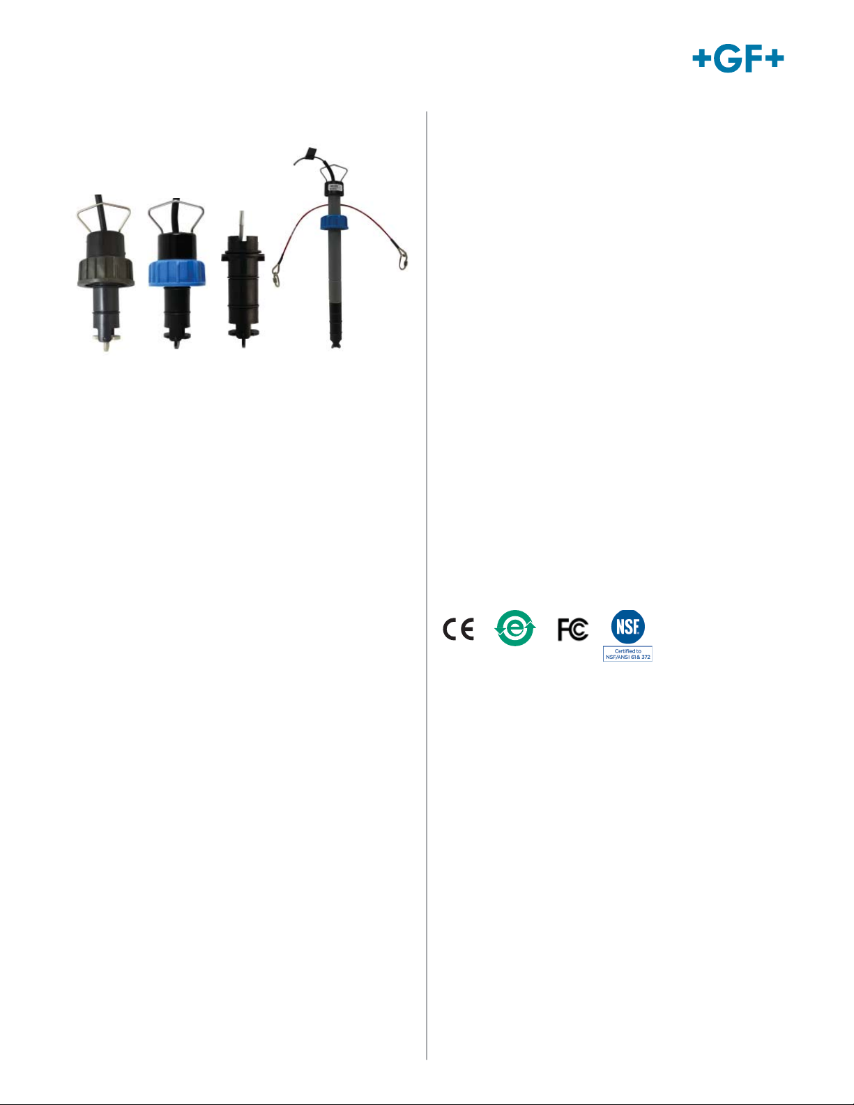
PVC
Sensor
(gray body
and cap)
Standard
Sensor
(blue cap)
Integral
Sensor
Wet-Tap
Sensor
(½ to 36 in.)
• PVC 2536 version DN15 to DN100 (½ to 4 in.) for
concentrated Sodium Hypochlorite 12.5% applications
• High resolution and noise immunity
Simple to install with time-honored reliable
performance, Signet 2536 Rotor-X Paddlewheel Flow
Sensors are highly repeatable, rugged sensors that
o er exceptional value with little or no maintenance.
The Model 2536 has a process-ready open collector
signal with a wide dynamic fl ow range of 0.1 to 6 m/s
(0.3 to 20 ft/s). The sensor measures liquid fl ow rates in
full pipes and can be used in low pressure systems.
The Signet 2536 sensors are o ered in a variety of
materials for a wide range of pipe sizes and insertion
confi gurations. The many material choices including
PP and PVDF make this model highly versatile and
chemically compatible to many liquid process solutions.
Sensors can be installed in DN15 to DN900 (½ to 36 in.)
pipes (except the 2536 PVC versions, which can be
installed in DN15 to DN100 (½ to 4 in.) pipes), using
Signet’s comprehensive line of custom fi ttings. These
custom fi ttings, which include tees, saddles, and
weldolets, seat the sensor to the proper insertion depth
into the process fl ow. The sensors are also o ered in
confi gurations for wet-tap installation requirements.
• Test certifi cate included for -X0, -X1
• Chemically resistant materials
(3-2536-PX
version only)
Applications
• Pure Water Production
• Filtration Systems
• Chemical Production
• Liquid Delivery Systems
• Pump Protection
• Scrubber/Gas Stacks
• Gravity Feed Lines
• Not suitable for gas
• Sodium Hypochlorite transfer/
injection/batching (3-2536-U0)
www.gfsignet.com
Page 2

Specifi cations
General
Operating Range 0.1 to 6 m/s 0.3 to 20 ft/s
Pipe Size Range DN15 to DN900 ½ to 36 in.
PVC DN15 to DN100 ½ to 4 in.
Linearity ±1% of max. range @ 25 °C (77 °F)
Repeatability ±0.5% of max. range @ 25 °C (77 °F)
Min. Reynolds Number Required 4500
Wetted Materials
Sensor Body Glass-fi lled PP (black), PVDF (natural) or PVC (gray)
O-rings
Rotor Pin Titanium, Hastelloy-C or PVDF; optional Ceramic, Tantalum or Stainless Steel
Rotor Black PVDF or Natural PVDF; optional ETFE, with or w/o carbon fi ber reinforced PTFE
Electrical
Frequency 49 Hz per m/s nominal 15 Hz per ft/s nominal
Supply Voltage 5 to 24 VDC ±10%, regulated
Supply Current <1.5 mA @ 3.3 to 6 VDC <20 mA @ 6 to 24 VDC
Output Type Open collector, sinking 10 mA max.
Cable Type 2-conductor twisted pair with shield, 22 AWG
Cable Length 7.6 m (25 ft) can be extended up to 305 m (1000 ft) maximum
Max. Temperature/Pressure Rating - Standard and Integral Sensor
PP 12.5 bar @ 20 °C 180 psi @ 68 °F
PVDF 14 bar @ 20 °C 200 psi @ 68 °F
PVC 12.5 bar @ 20 °C 180 psi @ 68 °F
Operating Temperature
PP -18 °C to 85 °C 0 °F to 185 °F
PVDF -18 °C to 85 °C 0 °F to 185 °F
PVC 0 °C to 50 °C 32 °F to 122 °F
Max. Temperature/Pressure Rating - Wet-Tap Sensor
PP 7 bar @ 20 °C 100 psi @ 68 °F
Operating Temperature -18 °C to 60 °C 0 °F to 140 °F
Max. Wet-Tap Sensor Removal
Rating
Shipping Weight
3-2536-X0 0.454 kg 1.00 lb
3-2536-X1 0.476 kg 1.05 lb
3-2536-X2 0.680 kg 1.50 lb
3-2536-X3 0.780 kg 1.72 lb
3-2536-X4 0.800 kg 1.76 lb
3-2536-X5 0.880 kg 1.94 lb
3-8512-X0 0.35 kg 0.77 lb
3-8512-X1 0.37 kg 0.81 lb
Standards and Approvals
CE, FCC, NSF (3-2536-PX only)
RoHS compliant, China RoHS
Manufactured under ISO 9001 for Quality and ISO 14001 for Environmental Management and
OHSAS 18001 for Occupational Health and Safety
FPM (std) optional EPR (EPDM) or FFPM
sleeve for rotor pin
1.7 bar @ 85 °C 25 psi @185°F
1.7 bar @ 85 °C 25 psi @ 185 °F
6.9 bar @ 60 °C 100 psi @ 140 °F
1.4 bar @ 60 °C 20 psi @ 140 °F
1.7 bar @ 22 °C 25 psi @ 72 °F
See Temperature and Pressure Graphs for more information
www.gfsignet.com
Page 3

26.7 mm
(1.05 in.)
-P3
thru
-P5
Dimensions
Standard Mount
PVC Mount
(0.5 to 4 in. pipe range only)
53.3 mm
(2.1 in.)
26.7 mm
(1.05 in.)
Pipe range
0.5 to 4 in. -X0 = 104 mm (4.1 in.)
5 to 8 in. -X1 = 137 mm (5.4 in.)
10 in. and up -X2 = 213 mm (8.4 in.)
Signet Instruments
8550 8900
9900 9900-1BC
Signet 2536
PVC, Standard, Wet-Tap or
8512 Integral Mount
Flow Sensors
-X0
thru
-X2
Signet Instruments
8550 with 3-8050 Universal Mount Kit
9900-1P 9900-1BC with Rear Enclosure
OR
ENTER
102 mm
(4.0 in.)
26.7 mm
(1.05 in.)
Pipe, Tank, Wall Mount
+
Integral Mount
(shown with Transmitter
sold separately)
96 mm
(3.8 in.)
+
-Y0 or -Y1
Signet Instruments
8550 9900
with 3-8051-X Integral Mount Kit
-Y0 or -Y1
Pipe range
0.5 to 4 in. -Y0 = 152 mm (6.0 in.)
5 to 8 in. -Y1 = 185 mm (7.3 in.)
OR
99.06 mm
(3.90 in.)
Field (Integral) MountPanel Mount
OR
ENTER
106 mm
(4.16 in.)
26.7 mm
(1.05 in.)
Wet-Tap Mount Sensor
with 3519 Wet-Tap Valve
(See 3519 product page for
more information).
Pipe range
0.5 to 4 in. -P3 = 297 mm (11.7 in.)
5 to 8 in. -P4 = 333 mm (13.1 in.)
10 in. and up -P5 = 409 mm (16.1 in.)
Automation System
0486 Profibus Concentrator
and Customer Supplied
Programmable Logic Controller or
Programmable Automation Controller
L IN+
L IN-
N/C
L OUT+
L OUT-
N/C
L IN+
L IN-
+5V OUT
DATA
GND
L IN+
L IN-
+5V OUT
DATA
GND
Out
In
S3LLoop
S3L Loop
USB
Profibus
Channel 5
Channel 6Channel 7
+
Valve
Signet 3-0486 Profibus Concentrator
Address
Power
Channel 1
Channel 2
Channel 3
24 VDC
0.40A Max
S3LFreq
S3LFreq
S3LFreq
+5V OUT
+5V OUT
+5V OUT
Freq IN
Freq IN
Freq IN
PWR+
PWR+
PWR+
PWR-
PWR-
PWR-
DATA
DATA
DATA
GND
GND
GND
PLC
+
Channel 4
S3LFreq
+5V OUT
Freq IN
DATA
GND
System Overview
Signet Fittings
For overview of Wet-Tap System, see 3519 product page
Application Tips
• Use the Conduit Adapter Kit to protect the
cable-to-sensor connection when used in outdoor
environments. See Accessories section for more
information.
• Use a sleeved rotor in abrasive liquids to
reduce wear.
All sold separately
• Sensor plug can be used to plug installation fi tting
after extraction of sensor from pipe.
• For liquids containing ferrous particles, use Signet
Magmeters.
• For systems with components of more than one
material, the maximum temperature/pressure
specifi cation must always be referenced to the
component with the lowest rating.
www.gfsignet.com
Page 4

Temperature/Pressure Graphs
Note:
The pressure/temperature graphs are specifically
for the Signet sensor. During system design the
specifications of all components must be considered. In
the case of a metal piping system, a plastic sensor will
reduce the system specification. When using a PVDF
sensor in a PVC piping system, the fitting will reduce the
system specification.
(bar)(psi)
14.5
210
13.8
200
13.1
190
12.4
180
11.7
170
11.0
160
10.3
150
9.7
140
9.0
130
8.3
120
7.6
110
6.9
100
6.2
90
5.5
80
4.8
70
4.1
60
3.4
50
2.8
40
2.1
30
1.4
20
.7
10
0
-20 0 20 40 60 80 100
°F°C-4 32 68 104 140 176 212
Polypropylene
PVDF
PVC
Ordering Notes
1) Most common part number combinations shown. For
all other combinations contact factory.
2) Other rotor and pin materials are available for
purchase from the factory and can be easily replaced
in the fi eld. See Accessories section.
Ordering Information
Model 2536 Standard Mount Paddlewheel
When choosing this style of sensor, the instrument can be mounted nearby on a pipe or wall or in a remote location up
to 305 m (1000 ft) by connecting the sensor through a standard 3-8050-1 universal junction box. Standard cable length
is 7.6 m (25 ft). Use Signet fi ttings for proper seating of the sensor into the process fl ow.
Mfr. Part No. Code Body Rotor Pin Material
Flow Sensor for use with remote mount instrument
DN15 to DN100 - ½ to 4 in.
3-2536-P0 198 840 143 Polypropylene Black PVDF Titanium
3-2536-T0 198 840 149 Natural PVDF Natural PVDF Natural PVDF
3-2536-U0 159 001 843 PVC Sleeved ETFE Titanium
3-2536-V0 198 840 146 Natural PVDF Natural PVDF Hastelloy-C
DN125 to DN 200 - 5 to 8 in
3-2536-P1 198 840 144 Polypropylene Black PVDF Titanium
3-2536-V1 198 840 147 Natural PVDF Natural PVDF Hastelloy-C
DN250 - DN900 - 10 to 36 in.
3-2536-P2 198 840 145 Polypropylene Black PVDF Titanium
www.gfsignet.com
Page 5

Ordering Information (continued)
Model 2536 Integral Mount Paddlewheel
When choosing this style of sensor, the instrument is mounted directly onto the sensor for a local display.
See guidelines below for instructions.
Mfr. Part No. Code Body Rotor Pin Material
Flow sensor for integral mounting on the 8150 or 8550 instrument using the 3-8051-X Flow Sensor Integral
Mount Kit (sold separately)
DN15 to DN100 - ½ to 4 in.
3-8512-P0 198 864 513 Polypropylene Black PVDF Titanium
3-8512-T0 198 864 518 Natural PVDF** Natural PVDF Natural PVDF
3-8512-V0 198 864 516 Natural PVDF** Natural PVDF Hastelloy-C
DN125 to DN200 - 5 to 8 in. (PP only)
3-8512-P1 198 864 514 Polypropylene Black PVDF Titanium
**Natural PVDF available ½ in. to 4 in. only
Guidelines: Combining a 2536 integral mount fl ow sensor with an integrally mounted instrument
Option 1
Once an integral mount sensor is chosen, it can be
mounted directly to a fi eld mount transmitter by
following these guidelines:
a) Order the 3-8051-X fl ow sensor integral mounting kit
(sold separately) to connect the sensor to
an instrument.
b) Order a fi eld mount transmitter (sold separately). The
following part numbers are compatible:
3-8550-3, 3-9900-1.
c) Assembling the sensor with the integral adapter and
instrument is quick and simple.
Model 2536 Wet-Tap Mount Paddlewheel Flow Sensor
When choosing this style of sensor, the instrument can be mounted nearby on a pipe or wall or in a remote location
up to 305 m (1000 ft) by connecting the sensor through a standard 3-8050-1 universal junction box. Standard
cable length is 7.6 m (25 ft). This style of sensor uses the 3519 Wet-Tap valve only (see individual product page
for more information).
Mfr. Part No. Code Body Rotor Pin Material
Flow Sensor for wet-tap mounting with the 3519 Wet-Tap Valve (sold separately)
DN15 to DN100 - ½ to 4 in.
3-2536-P3 159 000 758 Polypropylene Black PVDF Titanium
DN125 to DN200 - 5 to 8 in.
3-2536-P4 159 000 759 Polypropylene Black PVDF Titanium
DN250 to DN900 - 10 to 36 in.
3-2536-P5 159 000 760 Polypropylene Black PVDF Titanium
Guideline: Combining a 2536 Wet-Tap Sensor with a 3519 Wet-Tap Valve
a) Once a sensor is chosen, it can be mounted in a 3519 Wet-Tap Valve (sold separately)
b) Assembling a sensor with a 3519 Wet-Tap valve is quick and simple. These parts can also be ordered as complete
assemblies. See 3519 product page.
Model 2536 Ordering Notes
1) Other rotor and pin materials are available for
purchase from the factory and can be easily replaced
in the fi eld. See Accessories section.
Please refer to Wiring, Installation, Accessories and Fittings sections for more information.
www.gfsignet.com
Page 6

Accessories and Replacement Parts
Mfr. Part No. Code Description
Rotors
3-2536.320-1 198 820 052 Rotor, PVDF Black
3-2536.320-2 159 000 272 Rotor, PVDF Natural
3-2536.320-3 159 000 273 Rotor, ETFE
3-2536.322-1 198 820 056 Sleeved rotor, PVDF Black
3-2536.322-2 198 820 057 Sleeved rotor, PVDF Natural
3-2536.322-3 198 820 058 Sleeved rotor, ETFE
Rotor Pins
M1546-1 198 801 182 Pin, Titanium
M1546-2 198 801 183 Pin, Hastelloy-C
M1546-3 198 820 014 Pin, Tantalum
M1546-4 198 820 015 Pin, Stainless Steel
P51545 198 820 016 Pin, Ceramic
O-Rings
1220-0021 198 801 000 O-ring, FPM (2 required per sensor)
1224-0021 198 820 006 O-ring, EPR (EPDM) (2 required per sensor)
1228-0021 198 820 007 O-ring, FFPM (2 required per sensor)
Miscellaneous
P31536 198 840 201 Sensor plug, Polypropylene
P31542-3 159 000 464 Sensor cap, Blue
3-2536.555 159 500 532 Sensor cap, Gray
P31934 159 000 466 Conduit cap
P51589 159 000 476 Conduit adapter kit
5523-0222 159 000 392 Cable (per foot), 2 cond. w/shield, 22 AWG
3-2536.321 198 820 054 PVDF Natural, Rotor kit (rotor and pin)
3-8050 159 000 184 Universal mount kit
3-8050-1 159 000 753 Universal junction box
3-8050.390-1 159 001 702 Retaining nut replacement kit, NPT, Valox (for use with 8510 and 8512)
3-8050.390-3 159 310 116 Retaining nut replacement kit, NPT, PP (for use with 8510 and 8512)
3-8050.390-4 159 310 117 Retaining nut replacement kit, NPT, PVDF (for use with 8510 and 8512)
3-8051 159 000 187 Transmitter integral adapter (for use with 8510 and 8512)
3-8051-1 159 001 755 Transmitter integral mounting kit, NPT, PP (for use with 8510 and 8512)
3-8051-2 159 001 756 Transmitter integral mounting kit, NPT, PVDF (for use with 8510 and 8512)
3-2536.099 Rev L (07/16)
© Georg Fischer Signet LLC
3401 Aero Jet Avenue, El Monte, CA 91731-2882 U.S.A. • Tel. (626) 571-2770 • Fax (626) 573-2057 • www.gfsignet.com • e-mail: signet.ps@georgfi scher.com
Specifi cations subject to change without notice. All rights reserved. All corporate names and trademarks stated herein are the property of their respective companies.
www.gfsignet.com
 Loading...