

Page 1
Signet 2517 Brass Paddlewheel Flow Sensor
*3-2540.090*
3-2517.090 Rev. F 11/06 English
SAFETY INSTRUCTIONS
1. Do not remove from pressurized lines.
2. Do not exceed maximum temperature/pressure specifi cations.
3. Wear safety goggles or faceshield during installation/service.
4. Do not alter product construction.
5. Apply sealant or PTFE tape to sensor threads, inspecting threads to ensure integrity.
Do not install a sensor with damaged threads.
Pipe fi ttings MUST be installed by a certifi ed welder only. Signet will not assume liability of any kind for improper fi tting
installations.
2517 Hot-Tap sensor specifi cations and limitations depend on the lowest maximum rating of the components associated with
the system. a ball valve, a component of the system, is rated at a maximum 100 psi @ 175°F, limiting the entire system's
maximum pressure/temperature rating to 100 psi @ 175°F. All higher maximum specifi cations MUST yield to the component
with the lowest maximum specifi cation.
Maximum Operating Pressure/Temperature:
• 17 bar (250 psi) @ 82°C (180°F) with standard FPM sensor fi tting O-rings.
• 17 bar (250 psi) @ 100°C ( 212°F) with optional EPR sensor fi tting O-rings.
English
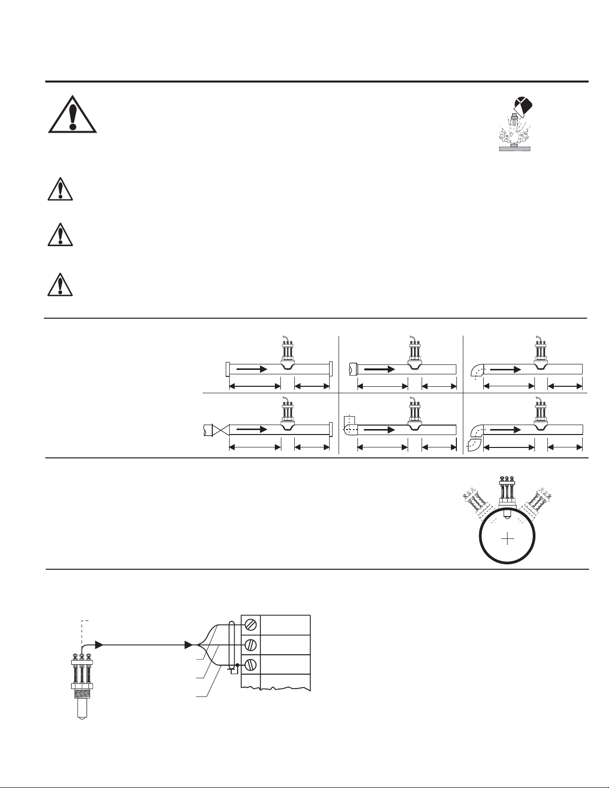
1. Location of Fitting
Recommended sensor upstream/
downstream
mounting requirements.
Inlet
Flange
10x I.D. 5x I.D.
Valve/Pump
50x I.D. 5x I.D.
Outlet
Reducer
15x I.D. 5x I.D.
2 x 90° Elbow
3 dimensions
40x I.D. 5x I.D.
2. Sensor Mounting Position
Vertical mounting is recommended for best overall performance. Mount at a maximum of 30°
when air bubbles are present. DO NOT mount on the bottom of the pipe when sediments are
present.
3. Sensor Wiring
Signet Instruments
1/2 in. NPT conduit port
Black
Blk, sensor
power
Red, freq.
input
Shld,
Gnd
Red
Silver
instrument
90° Elbow
20x I.D. 5x I.D.
2 x90° Elbow
25x I.D. 5x I.D.
0°
-
30°
Process Pipe
+30°
• Use 2-conductor shielded cable for cable extensions up to 300m (1000 ft.)
• Maintain cable shield through splice.
Page 2
5. Installation
The following items are required to properly install Signet 2217 Sensors.
5.1 Hardware, Standard Sensor
• Female pipe fi tting (weld-on or saddle) with 1.5 in. NPT or ISO 7/1-Rc 1.5 threads
• 32 mm (1.25 in.) diameter drill
• Pipe thread sealant
• Tape measure
5.2 Hardware, Hot-Tap Sensor
The Hot-Tap sensor requires all the standard sensor items plus:
• Hot-Tap drilling machine (e.g., Mueller drilling machine or equivalent)
• Female ball or gate valve (full port only) with 1.5 in. NPT or ISO 7/1-Rc 1.5 threads
• Male pipe nipple, 32 x 50 mm (1.5 x 2 in.) with 1.5 in. NPT or ISO 7/1-R 1.5 threads
• Hot-Tap installation tool (purchased separately)
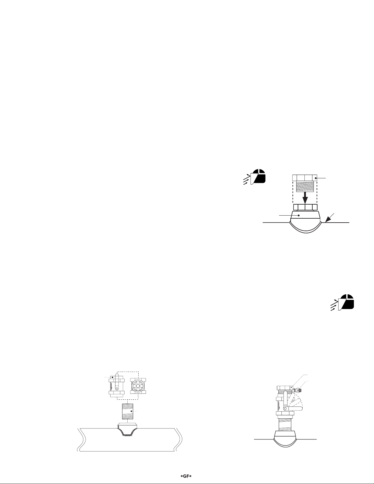
5.3 Standard Fitting Installation
A. Depressurize and drain pipe.
B. Wearing safety face protection, drill a 32 mm (1.25 in.) diameter hole in the pipe.
sensor
fitting
C. Install the pipe fi tting of the outside of the pipe according to the manufacturer's
instructions. Failure to follow these instructions may result in serious bodily injury
and/or product failure.
pipe
D. Remove sensor fi tting from sensor assembly.
E. Thread sensor fi tting into pipe fi tting. (Fig. 1)
5.4 Hot-Tap Fitting Installation
A. Install the pipe fi tting on the outside diameter of the pipe according to the manufacturer's instructions. Failure to follow these
instructions may result in serious bodily injury and/or product failure.
B. Install the pipe nipple and isolation valve (ball or gate valve) onto the external pipe fi tting using pipe sealant on the
threads. (Fig. 2)
C. Wearing safety face protection, install an appropriate hole cutting tool per manufacturer's instructions (e.g., Mueller
drilling machine) with a 32 mm (1.25 in.) drill onto the top of the isolation valve, ensuring a tight fi t. Use the
recommended drill bit size or damage to the isolation valve may occur.
D. Open the isolation valve and insert the drill through the valve and cut the sensor clearance hole. After the hole is cut, withdraw the
drill from the isolation valve and close the valve. Remove the drilling machine per manufacturer's instructions. (Fig. 3)
fitting
pipe sealant recommended
process
pipe
E. Install the sensor fi tting/bleed valve into the top of the isolation valve. Make sure the bleed valve clears the handle of the isolation
valve during operation.
customer supplied
ball or gate valve
Fig. 2
process pipe (side view)
2517 Brass Paddlewheel Flow Sensor
customer supplied
nipple: 32 x 50 mm
(1.25 x 2 in.) long
Fig. 3
process pipe
sensor fitting
bleed valve
make sure
bleed valve
clears isolation
valve handle
2
Page 3
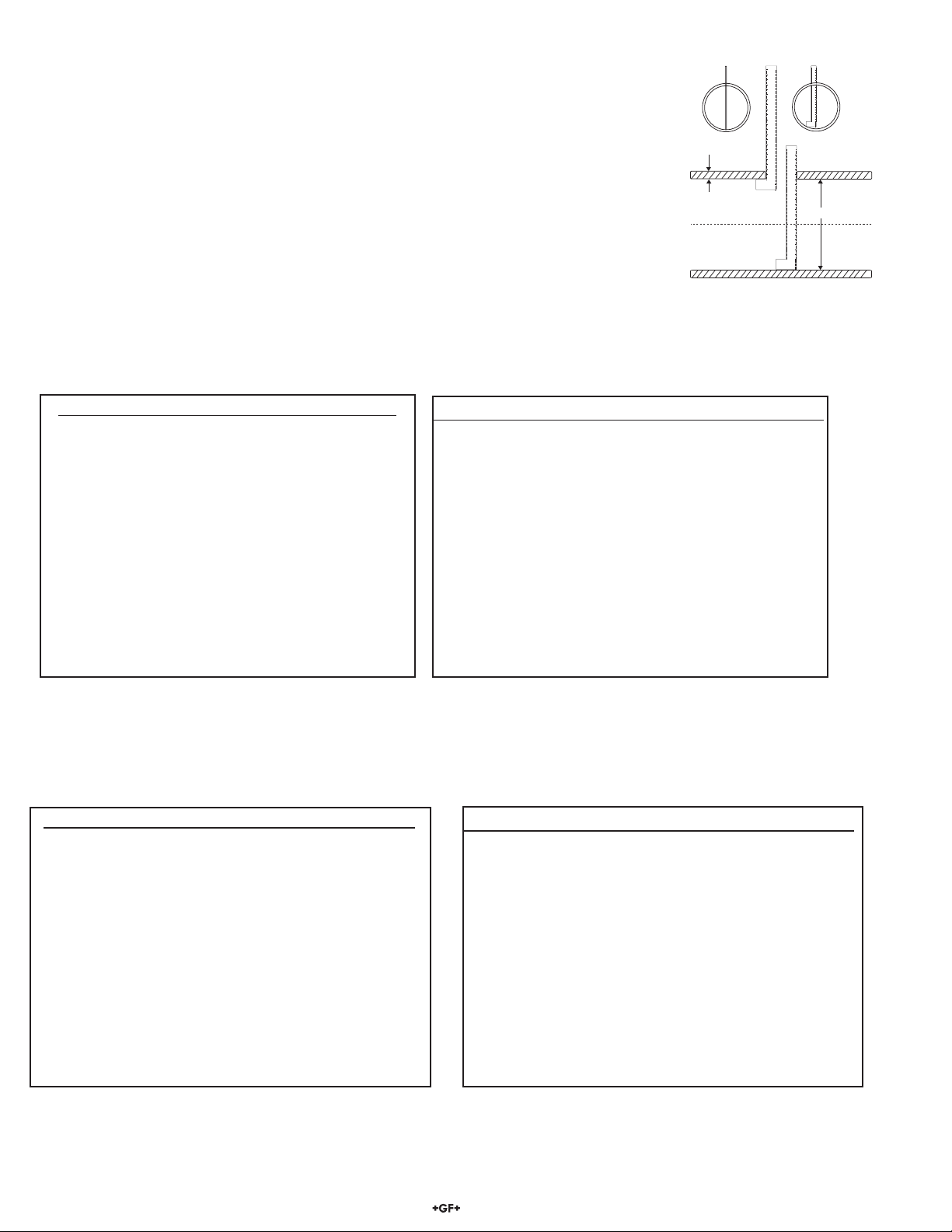
5.5 Calculating the H Dimension
Before installing the sensor some critical dimensions must be established (for Hot-Tap installations,
we assume the pipe dimensions are known). The rotor shaft must be located 10% inside the pipe
I.D. to ensure accurate calibration capability. To accomplish this, the "H" dimension is measured
from the outside surface of the pipe to the bottom of the sensor fl ange.
Nominal "H" dimensions for standard pipes are listed here. For non-standard pipe dimensions,
calculate the "H" dimension using the formula listed below. Your pipe's wall thickness and inside
diameter (I.D.) is required for the "H" dimension calculation.
The 6 inch ruler (included) may be used to measure your pipe I.D. and wall thickness up to 5 inches
(standard sensors only).
Pipe wall thickness: __________ Pipe I.D.: ___________
correct
wall
thickness
6
6
5
5
4
3
2
1
B
incorrect
6
5
5
4
4
3
3
2
2
1
1
A
B
5
4
4
3
3
2
2
1
1
A
B
pipe I.D.
5
4
3
2
1
A
H Dimensions, Standard Sensors
NPS SCH 40 SCH 80 STD XS
1-1/2 in.
2 in.
2-1/2 in.
3 in.
3-1/2 in.
4 in.
5 in.
6 in.
8 in.
10 in.
12 in.
14 in.
16 in.
18 in.
20 in.
22 in.
24 in..
5.644 in.
5.589 in.
5.500 in.
5.427 in.
5.369 in.
5.310 in.
5.187 in.
5.064 in.
4.830 in.
4.583 in.
4.350 in.
4.200 in.
3.950 in.
3.700 in.
3.475 in.
*
3.000 in.
5.600 in.
5.538 in.
5.442 in.
5.360 in.
5.296 in.
5.230 in.
5.094 in.
4.942 in.
4.688 in.
4.400 in.
4.125 in.
3.950 in.
3.675 in.
3.400 in.
3.125 in.
2.850 in.
2.575 in.
5.644 in.
5.589 in.
5.500 in.
5.427 in.
5.369 in.
5.310 in.
5.187 in.
5.064 in.
4.830 in.
4.583 in.
4.375 in.
4.250 in.
4.050 in.
3.850 in.
3.650 in.
3.450 in.
3.250 in.
5.600 in.
5.538 in.
5.442 in.
5.360 in.
5.296 in.
5.230 in.
5.094 in.
4.942 in.
4.688 in.
4.475 in.
4.275 in.
4.150 in.
3.950 in.
3.750 in.
3.550 in.
3.350 in.
3.150 in.
(*) represents values currently unavailable
H Dimensions for Hot-Tap Sensors
Wrought Steel Pipe Per ANSI 36.10
Stainless Steel Pipe Per ANSI B36.19Wrought Steel Pipe Per ANSI 36.10 Conversion:
mm = inches (25.4)
NPS SCH 5S SCH 10S SCH 40S SCH 80S
1-1/2 in.
2 in.
2-1/2 in.
3 in.
3-1/2 in.
4 in.
5 in.
6 in.
8 in.
10 in.
12 in.
14 in.
16 in.
18 in.
20 in.
22 in.
24 in.
5.708 in.
5.660 in.
5.596 in.
5.534 in.
5.484 in.
5.434 in.
5.306 in.
5.200 in.
5.000 in.
4.768 in.
4.550 in.
4.425 in.
4.218 in.
4.018 in.
3.800 in.
3.600 in.
3.376 in.
Stainless Steel Pipe Per ANSI B36.19
5.673 in.
5.625 in.
5.567 in.
5.504 in.
5.454 in.
5.404 in.
5.287 in.
5.180 in.
4.969 in.
4.743 in.
4.531 in.
4.400 in.
4.200 in.
4.000 in.
3.776 in.
3.576 in.
3.350 in.
5.644 in.
5.589 in.
5.500 in.
5.427 in.
5.369 in.
5.310 in.
5.187 in.
5.064 in.
4.830 in.
4.583 in.
4.375 in.
*
*
*
*
*
*
5.600 in.
5.538 in.
5.442 in.
5.360 in.
5.296 in.
5.230 in.
5.094 in.
4.942 in.
4.688 in.
4.475 in.
4.275 in.
*
*
*
*
*
*
Conversion:
mm = inches (25.4)
NPS SCH 40 SCH 80 STD XS
1-1/2 in.
2 in.
2-1/2 in.
3 in.
3-1/2 in.
4 in.
5 in.
6 in.
8 in.
10 in.
12 in.
14 in.
16 in.
18 in.
20 in.
22 in.
24 in.
14.694 in.
14.639 in.
14.550 in.
14.477 in.
14.419 in.
14.360 in.
14.237 in.
14.144 in.
13.880 in.
13.633 in.
13.400 in.
13.250 in.
13.000 in.
12.750 in.
12.525 in.
*
12.050 in.
14.650 in.
14.588 in.
14.492 in.
14.410 in.
14.346 in.
14.280 in.
14.144 in.
13.992 in.
13.738 in.
13.450 in.
13.175 in.
13.000 in.
12.725 in.
12.450 in.
12.175 in.
11.900 in.
11.625 in.
14.694 in.
14.639 in.
14.550 in.
14.477 in.
14.419 in.
14.360 in.
14.237 in.
14.144 in.
13.880 in.
13.633 in.
13.425 in.
13.300 in.
13.100 in.
12.900 in.
12.700 in.
12.500 in.
12.300 in.
14.650 in.
14.588 in.
14.492 in.
14.410 in.
14.346 in.
14.280 in.
14.144 in.
13.992 in.
13.738 in.
13.525 in.
13.325 in.
13.200 in.
13.000 in.
12.800 in.
12.600 in.
12.400 in.
12.200 in.
(*) represents values currently unavailable
3
NPS SCH 5S SCH 10S SCH 40S SCH 80S
1-1/2 in.
2 in.
2-1/2 in.
3 in.
3-1/2 in.
4 in.
5 in.
6 in.
8 in.
10 in.
12 in.
14 in.
16 in.
18 in.
20 in.
22 in.
24 in.
14.758 in.
14.711 in.
14.646 in.
14.584 in.
14.534 in.
14.484 in.
14.357 in.
14.250 in.
14.050 in.
13.818 in.
13.600 in.
13.475 in.
13.268 in.
13.068 in.
12.850 in.
12.650 in.
12.426 in.
14.723 in.
14.675 in.
14.617 in.
14.554 in.
14.504 in.
14.454 in.
14.337 in.
14.230 in.
14.019 in.
13.793 in.
13.581 in.
13.450 in.
13.250 in.
13.050 in.
12.826 in.
12.626 in.
12.400 in.
14.694 in.
14.639 in.
14.550 in.
14.477 in.
14.419 in.
14.360 in.
14.237 in.
14.144 in.
13.880 in.
13.633 in.
13.425 in.
*
*
*
*
*
*
14.650 in.
14.588 in.
14.492 in.
14.410 in.
14.346 in.
14.280 in.
14.144 in.
13.992 in.
13.738 in.
13.525 in.
13.325 in.
*
*
*
*
*
*
2517 Brass Paddlewheel Flow Sensor
Page 4
Standard Sensors
H = 5.23 - pipe wall thickness - (0.10 X I.D.)
sensor flange
alignment rod
Example:
3.0 inch schedule 80 wrought steel;
Wall thickness = 0.3 in. / Inside diameter = 2.9 in.
H = 5.23 - 0.3 - (0.10 X 2.9) / H = 117.86 mm (4.64 in.)
Record your sensor's "H" dimension for future reference:
H= ___________
Hot-Tap Sensors
H = 15.39 in. - pipe wall thickness - (0.10 X I.D.)
Example:
10 inch schedule 40 wrought steel;
Wall thickness= 0.365 in. / Inside diameter = 10.02 in.
H = 15.39 - 0.365 - (0.10 X 10.02) / H = 356.18 mm (14.023 in.)
Record your sensor's "H" dimension for future reference:
H= ___________
After correct dimensions are calculated and recorded, the sensor can
be installed in the fi tting. The Standard and Hot-Tap versions require
substantially different procedures.
pipe side view
sensor flange
"H"
pipe side view
direction
of flow
"H"
process pipe
direction
of flow
alignment rod
process pipe
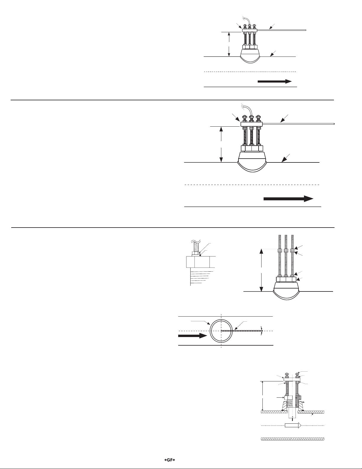
5.6 Standard Sensor Installation
A. Thread one hex nut onto each of the three threaded rods
included in package. Install threaded rod with a lock washer
onto the sensor fi tting. Secure rods in place by tightening each
hex nut against the sensor fi tting. (Fig. 4)
B. Thread one jam nut and lower hex nut onto each threaded
rod so that the top surface of each nut is at the proper "H"
dimension for your pipe. Secure each hex nut with a jam nut.
(Fig. 5)
C. Insert the fl ow sensor into the sensor fi tting, making sure the
alignment hole on the sensor fl ange is pointing downstream.
D. Place the alignment rod in the alignment hole on the sensor
fl ange. Align the fl ange so rod is parallel to the process pipe.
(Fig. 6)
E. Thread upper hex nuts with lock washers until they contact the
sensor fl ange and tighten. Check for proper "H" dimension
and readjust if necessary. (Fig. 7)
D. Place the alignment rod in the alignment hole on the sensor
fl ange. Align the fl ange so rod is parallel to the process pipe.
(Fig. 6)
E. Thread upper hex nuts with lock washers until they contact the
sensor fl ange and tighten. Check for proper "H" dimension and
readjust if necessary. (Fig. 7)
Fig. 4
hex nut
Lock washer
"H"
sensor fitting
Fig. 5
sensor
flange
flow direction
alignment
rod
process pipe
(top view)
The flow sensor alignment rod MUST be
parallel to the process pipe as shown.
"H"
sensor
flange
jam nuts
sensor
fitting
Fig. 6
FLOW
lower hex nuts
(3/16 x 1/4-20)
jam nuts
(5/32 x 1/4-20)
hex nut &
lock washer
sensor fitting
process pipe
cap nuts
upper hex nuts
& lockwashers
lower hex nuts
female pipe fitting
process
pipe wall I.D.
4
Fig. 7
2517 Brass Paddlewheel Flow Sensor
Page 5

5.7 Hot-Tap Sensor Installation
A. Thread one hex nut onto each of the three threaded rods included
in package. Install threaded rod with a lock washer onto the
sensor fi tting. Secure rods in place by tightening each hex nut
against the sensor fi tting. (Fig. 8)
hex nut
Lock washer
B. Thread one jam nut and lower hex nut onto each threaded rod so
that the top surface of each nut is 359 mm (14.14 in.) from the top
surface of the sensor fi tting. Secure each hex nut with a jam nut.
(Fig. 9)
CAUTION: This setting is critical to ensure an adequate
sensor seal and to prevent the rotor from hitting the
isolation valve orifi ce during installation.
C. Wipe the sensor body with a dry, clean cloth. Orient the alignment
hole on the sensor fl ange to point downstream. Place the slotted
fl ange over the threaded rods. Lower the sensor into the fi tting
until the sensor fl ange rests on the lower hex and jam nuts.
D. Secure the sensor with lock washers and upper hex nuts on the
top of the fl ange. Before tightening, align the sensor fl ange so that
the alignment rod is parallel and level with the
process pipe. (Fig. 10 & Fig. 11)
E. Make sure the bleed valve is closed (full clockwise position).
F. Thread protector plate hex nuts onto each of the three threaded
rods. Adjust each hex nut to a height of approximately 25 mm
(1 in.) from the top of each rod. Remove the black plastic cable
grommet in top of sensor with a screwdriver. Slide the grommet up
the cable away from sensor. (Fig. 12)
Fig. 8
Fig. 9
sensor
flange
sensor fitting
359 mm
(14.14 in.)
sensor
fitting
UNDER PRESSURE!
lower hex nuts
(3/16 x 1/4-20)
jam nuts
(5/32 x 1/4-20)
alignment
rod
sensor flange
lower hex nut
and jam nuts
18 inch
threaded rods
sensor
fitting
Fig. 11
Upper hex nuts
(3/16 x 1/4-20)
1/4 in. lock
washers
alignment rod
359 mm (14.14 in)
direction
of flow
process pipe (side view)
bleed valve
protector plate
cap nuts
25mm
(1.0 in.)
cable
grommit
flow direction
process pipe
(top view)
The flow alignment rod MUST be
parallel to the process pipe as shown.
Fig. 10
protector plate
removed during
sensor installation
protector plate
hex nut (3/16 x
1/4-20)
Fig. 12
2517 Brass Paddlewheel Flow Sensor
5
Page 6

Hot-Tap Sensor Installation - Continued
G. Position the installation tool bearing plate by rotating it so that it is approximately 40 mm (1.6 in.) from the swivel mount. Mount
the installation tool by placing the threaded rods through the holes in the tool's bearing plate, resting the bearing plate on top of
the protector plate hex nuts. Make sure the swivel mount's ears are mounted between the threaded rods (not over the rods).
Install the bearing plate cap nuts. Tighten the bearing plate cap nuts to secure the installation tool in place. (Fig. 13)
H. Align the sensor cable with the swivel mount cable port to prevent cable pinching. Use a 3/8 inch wrench or socket to turn the
installation tool shaft clockwise until it is seated in the hole at the top of the sensor fl ange.
I. Wearing safety face protection, slowly open the isolation valve to the full open position. Loosen the lower hex and
jam nuts and move them to the proper "H" dimension. Turn the installation tool shaft clockwise until the sensor fl ange
contacts the lower hex and jam nuts. Thread the upper hex nuts down until they contact the sensor fl ange. Tighten the
upper hex nuts to secure the sensor. (Fig. 14)
J. Remove cap nuts and withdraw the installation tool. Be careful to not damage cable. Snap cable grommet into top of sensor
and replace protector plate and cap nuts. (Fig. 15)
Fig. 14
Fig. 13
installation
tool shaft
upper hex nuts
cap nuts
alignment rod
cap nuts
protector plate
hex nuts
sensor
cable
installation tool
threaded shaft
bearing plate
swivel mount
w/cable port
sensor flange
"H"
lower hex nuts
jam nuts
isolation valve
Fig. 15
protector plate
cap nuts
protector plate
protector plate
sensor body
hex nut
direction
of flow
6. Standard Sensor Removal
To remove the sensor from a depressurized empty pipe, simply remove the cap nuts and upper hex nuts located above the sensor
fl ange. Pull up on sensor fl ange with twisting motion.
7. Hot-Tap Sensor Removal
installation tool
To remove the Hot-Tap sensor safely from a pressurized active pipe, the entire installation
process must be reversed.
A. Remove the cap nuts, protector plate, protector plate hex nuts, and sensor cable grommet.
(Fig. 16)
B. Thread installation tool in place and secure bearing plate in place of sensor protector plate.
(Fig. 17)
372 mm
(14.6 in.)
threaded shaft
upper hex nuts
and lock washers
sensor flange
lower hex and
jam nuts
sensor fitting
C. Turn shaft of installation tool clockwise to lower tool into opening in sensor fl ange. Guide
cable into the port to prevent damage.
protector plate
Fig. 16
6
cap nuts
protector plate
protector plate
hex nut
Fig. 17
isolation valve
UNDER PRESSURE!
process pipe (side view)
2517 Brass Paddlewheel Flow Sensor
Page 7

r
Hot-Tap Sensor Removal - Continued
D. Wearing safety face protection, loosen the upper hex nuts and raise to 372 mm (14.6 in.) from top of sensor fi tting to
bottom of upper hex nuts/lock washers. CAUTION! This measurement is critical to maintain watertight seal in
sensor while allowing clearance to close the isolation valve.
E. Wearing safety face protection, turn the installation tool shaft
counterclockwise to withdraw sensor until the sensor fl ange contacts
the upper hex nuts. (Fig. 18)
F. Raise one lower hex and jam nut to bottom of sensor fl ange.
G. Close isolation valve, remove bearing plate and tool.
H. Wearing safety face protection, cover the bleed valve with suitable
protection (rag, towel, etc.) and open the bleed valve (ccw rotation)
to relieve internal pressure. Pull sensor up until bleed valve purges
some fl uid (indicating sensor is past 1st o-ring seal inside sensor
fi tting).
cap nuts
protector plate
hex nuts
upper hex nuts
installation tool
threaded shaft
installation tool
bearing plate
swivel mount
w/cable port
sensor flange
1 lower hex nut
and jam nut
sensor body
CAUTION: In case of a leaky isolation valve, the sensor will be under a slight amount
of pressure. Care should be taken when removing the sensor. Use the bleed valve to
Fig. 18
relieve this pressure taking care not to spray fl uid on yourself or others.
Sensor can now be safely removed. When reinstalling the sensor: leave one lower hex nut in position to guide sensor to proper
isolation valve clearance height before opening isolation valve. Return to "H" dimension height after valve is opened.
8. Maintenance
Your sensor requires little or no maintenance of any kind, with the exception of an occasional sensor/paddlewheel cleaning.
9. Sensor Parts
2517 Sensor Assemblies
Order no. Sensor type Fitting type Code
3-2517.100 Standard 1.5 in. NPT 159 840 003
3-2517.101 Standard IS0 7/1-R 1.5 159 840 007
3-2517.102 Hot-Tap 1.5 in. NPT 159 000 267
3-2540.103 Hot-Tap IS0 7/1-R 1.5 159 000 268
Accessories
Order no. Description Code
3-1500.663 Hot-Tap installation tool 198 820 008
P52509-3 Rotor kit w/Tungsten Carbide pin Fluoroloy-B bearings, 316 ss retainers 159 001 068
P52509-1 Rotor kit w/316 ss pin, Fluoroloy-B bearings, 316 ss retainers 159 000 479
1220-0121* Standard FPM O-ring for sensor fi tting 159 000 852
1224-0021* Optional EPDM O-ring for sensor fi tting 198 820 006
P52504-2 Replacement rotor pin, tungsten carbide 198 820 023
P52504-1 Replacement rotor pin, 316 ss 198 801 500
3-2517.567 Cable, per ft. 159 000 269
*One O-ring required for standard sensor
Two O-rings required for Hot-Tap sensor
retainer retaine
bearing
rotor pin
bearing
2517 Brass Paddlewheel Flow Sensor
rotor
7
Page 8

10. K-Factors (Stainless Steel, Wrought Steel & Plastic Pipe)
SCH 40 WROUGHT STEEL PIPE PER ANSI B36.10
K-FACTOR K-FACTOR
PIPE PULSES/ PULSES/
SIZE U.S. GAL LITER
1 ½ 122.000 32.232
2 78.690 20.790
2 ½ 55.630 14.697
3 35.530 9.3871
3 ½ 26.070 6.8877
4 19.840 5.2417
5 12.090 3.1942
6 8.0410 2.1244
8 4.3500 1.1493
10 2.6080 0.6890
12 1.7610 0.4653
14 1.4250 0.3765
16 1.0590 0.2798
18 0.8180 0.2161
20 0.6460 0.1707
22 * *
24 0.4350 0.1149
SCH 5S STAINLESS STEEL PIPE PER ANSI B36.19
K-FACTOR K-FACTOR
PIPE PULSES/ PULSES/
SIZE U.S. GAL LITER
1 ½ 104.200 27.5297
2 67.160 17.7437
2 ½ 46.060 12.1691
3 29.790 7.8705
3 ½ 22.060 5.8283
4 16.890 4.4624
5 10.6500 2.8137
6 7.1160 1.8801
8 3.8700 1.0225
10 2.3570 0.6227
12 1.6060 0.4243
14 1.2980 0.3429
16 0.9620 0.2542
18 0.7400 0.1955
20 0.5900 0.1559
22 0.4790 0.1266
24 0.3990 0.1054
SCH 80 WROUGHT STEEL PIPE PER ANSI B36.10
K-FACTOR K-FACTOR
PIPE PULSES/ PULSES/
SIZE U.S. GAL LITER
1 ½ 136.100 35.9577
2 88.590 23.4055
2 ½ 62.810 16.5945
3 39.990 10.5654
3 ½ 29.220 7.7199
4 22.160 5.8547
5 13.420 3.5456
6 9.0160 2.3820
8 4.8190 1.2732
10 2.8970 0.7654
12 1.9620 0.5184
14 1.5890 0.4198
16 1.1750 0.3104
18 0.9040 0.2388
20 0.7160 0.1892
22 0.5820 0.1538
24 0.4820 0.1273
K-factors are listed in U.S. gallons and in liters. Conversion formulas for other engineering units are listed below.
• K = 60/A
SCH 10S STAINLESS STEEL PIPE PER ANSI B36.19
K-FACTOR K-FACTOR
PIPE PULSES/ PULSES/
SIZE U.S. GAL LITER
1 ½ 113.600 30.0132
2 72.560 19.1704
2 ½ 48.750 12.8798
3 31.250 8.2563
3 ½ 23.010 6.0793
4 17.540 4.6341
5 10.8700 2.8719
6 7.2410 1.9131
8 3.9520 1.0441
10 2.3880 0.6309
12 1.6200 0.4280
14 1.3110 0.3464
16 0.9680 0.2557
18 0.7440 0.1966
20 0.5930 0.1567
22 0.4820 0.1273
24 0.4020 0.1062
8
The K-factor is the number of pulses generated by the 2517 paddlewheel per unit of liquid in a specifi c pipe size.
To convert multiply
K from: to: K by:
U.S. gallons cubic feet 7.479
U.S. gallons cubic inches 0.00433
U.S. gallons cubic meters 263.85
U.S. gallons pounds of water 0.120
U.S. gallons acre feet 325853
U.S. gallons Imperial gallons 1.201
2517 Brass Paddlewheel Flow Sensor
Page 9

10. K-Factors (Stainless Steel, Wrought Steel & Plastic Pipe) continued
STD WROUGHT STEEL PIPE PER ANSI B36.10
K-FACTOR K-FACTOR
PIPE PULSES/ PULSES/
SIZE U.S. GAL LITER
1 ½ 122.000 32.2325
2 78.690 20.7900
2 ½ 55.630 14.6975
3 35.530 9.3871
3 ½ 26.070 6.8877
4 19.840 5.2417
5 12.090 3.1942
6 8.0410 2.1244
8 4.3500 1.1493
10 2.6080 0.6890
12 1.7400 0.4597
14 1.3950 0.3686
16 1.0220 0.2700
18 0.7800 0.2061
20 0.6150 0.1625
22 0.4970 0.1313
24 0.4110 0.1086
XS WROUGHT STEEL PIPE PER ANSI B36.10
K-FACTOR K-FACTOR
PIPE PULSES/ PULSES/
SIZE U.S. GAL LITER
1 ½ 136.100 35.9577
2 88.590 23.4055
2 ½ 62.810 16.5945
3 39.990 10.5654
3 ½ 29.220 7.7199
4 22.160 5.8547
5 13.420 3.5456
6 9.0160 2.3820
8 4.8190 1.2732
10 2.7730 0.7326
12 1.8240 0.4819
14 1.4550 0.3844
16 1.0590 0.2798
18 0.8050 0.2127
20 0.6320 0.1670
22 0.5100 0.1347
24 0.4200 0.1110
SCH 40S STAINLESS STEEL PIPE PER ANSI B36.19
K-FACTOR K-FACTOR
PIPE PULSES/ PULSES/
SIZE U.S. GAL LITER
1 ½ 122.000 32.2325
2 78.690 20.7900
2 ½ 55.630 14.6975
3 35.530 9.3871
3 ½ 26.070 6.8877
4 19.840 5.2417
5 12.090 3.1942
6 8.0410 2.1244
8 4.3500 1.1493
10 2.6080 0.6890
12 1.7400 0.4597
14 * *
16 * *
18 * *
20 * *
22 * *
24 * *
SCH 80S STAINLESS STEEL PIPE PER ANSI B36.19
K-FACTOR K-FACTOR
PIPE PULSES/ PULSES/
SIZE U.S. GAL LITER
1 ½ 136.100 35.9577
2 88.590 23.4055
2 ½ 62.810 16.5945
3 39.990 10.5654
3 ½ 29.220 7.7199
4 22.160 5.8547
5 13.420 3.5456
6 9.0160 2.3820
8 4.8190 1.2732
10 2.7730 0.7326
12 1.8240 0.4819
14 * *
16 * *
18 * *
20 * *
22 * *
24 * *
2517 Brass Paddlewheel Flow Sensor
9
Page 10

10. K-Factors (Stainless Steel, Wrought Steel & Plastic Pipe) continued
Schedule 40 Plastic pipe per ASTM-D-1785
K-FACTOR K-FACTOR
PIPE PULSES/ PULSES/
SIZE U.S. GAL LITER
1 1/2 124.400 32.8666
2 80.140 21.1731
2 1/2 56.730 14.9881
3 36.180 9.5588
3 1/2 26.500 7.0013
4 20.140 5.3210
5 12.250 3.2365
6 8.1430 2.1514
8 4.3980 1.1620
10 2.6340 0.6959
12 1.7770 0.4695
11. Specifi cations
General
Flow Rate Range:
0.5 to 6 m/s (1 .6 to 20 ft/s)
Linearity: ±1% of full range
Repeatability: ±0.5% of full range
Min. Reynolds Number Required: 4500
Pipe size range:
• Standard version: DN40 to DN600
(1 .5 to 24 in.)
• Hot-Tap version: DN40 to DN900
(1 .5 to 36 in.)
Sensor fi tting options:
• 1 .5in NPT threads
• ISO 7/1-R 1 .5 threads
Wetted materials
Sensor body: C36000 Free cutting brass
Sensor fi tting: C36000 Free cutting brass
Sensor fi tting O-rings:
Standard Viton®, optional EPR
Rotor: CB7Cu-1 Alloy
Rotor pin: Tungsten Carbide GRP 1
Retainers (2): 316 stainless steel
Rotor bearings (2): Fluoroloy B
Electrical
Frequency: 20 Hz per ft/s nominal,
5 to 8 mV p-p per Hz
Source Impedance: 11 .6 KΩ
Cable length: 7.6 m (25 ft.), can be extended up to
60m (200 ft.)
Cable type: 2-conductor twisted-pair with shield,
22AWG
Max. Pressure/Temperature Rating
• Sensor with standard FPM sensor fi tting O-rings:
17 bar @ 82°C (250 psi @ 180°F)
• Sensor with optional EPDM sensor fi tting O-rings:
17 bar @ 100°C (250 psi @ 212°F)
See page 226 for Temperature and Pressure graphs.
Shipping Weight:
• 3-2517.100, .101: 2.04 kg (4.5 lbs.)
• 3-2517.102, .103: 2.63 kg (5.8 lbs.)
®
Schedule 80 Plastic pipe per ASTM-D-1785
K-FACTOR K-FACTOR
PIPE PULSES/ PULSES/
SIZE U.S. GAL LITER
1 ½ 139.400 36.8296
2 90.790 23.9868
2 ½ 64.610 17.0700
3 41.050 10.8454
3 ½ 29.940 7.9102
4 22.660 5.9868
5 13.700 3.6196
6 9.1990 2.4304
8 4.9060 1.2962
10 2.9450 0.7781
12 1.9930 0.5266
Standards and Approvals
• Manufactured under ISO 9001:2000 for Quality and
ISO 14001:1996 for Environmental Management
• FM approved, CE.
Caution: The 2517 Hot-Tap system's overall
specifi cations and limitations depend on the lowest
maximum rating of the components associated with the
system. In other words, the Hot-Tap system is only as
strong as its weakest link. For example, a ball valve, a component
of the system, is rated at a maximum 100 psi @ 175 °F, limiting the
entire system's maximum pressure/temperature rating to 100 psi
@ 175 °F. All higher maximum specifi cations MUST yield to the
component with the lowest maximum specifi cation.
Note: Pressure/temperature specifi cations refer to sensor
performance in water. Certain chemical limitations may apply.
Chemical compatibilityshould be verifi ed.
64 mm (2.5 in.) dia.
7.5 m (25 ft.)
integral cable
127 mm
Adjustable
length
O-ring
seal (1)
Standard Sensor Dimensions:
• 2540-1 = 1.5 in. NPT fi tting
• 2540-2 = IS0 7/1-R 1.5 fi tting
(5.0 in.)
Sensor fitting:
1.5 in. NPT or
ISO 7/1-R 1.5
thread
24 mm (0.94 in.) dia.
64 mm (2.5 in.) dia.
7.6 m
(25 ft.)
cable
O-ring
seals (2)
Adjustable
length
457 mm
(18 in.)
Sensor fitting:
1.5 in. NPT or
ISO 7/1-R 1.5
thread
24 mm (0.94 in.) dia.
Hot-Tap Sensor Dimensions:
• 2540-3 = 1.5 in. NPT fi tting
• 2540-4 = IS0 7/1-R 1.5 fi tting
Bleed
valve
10
2517 Brass Paddlewheel Flow Sensor
Page 11

Notes:
2517 Brass Paddlewheel Flow Sensor
11
Page 12

Notes:
George Fischer Signet Inc., 3401 Aerojet Avenue, El Monte, CA 91731-2882 U.S.A. • Tel. (626) 571-2770 • Fax (626) 573-2057
For Worldwide Sales and Service, visit our website: www.gfsignet.com • Or call (in the U.S.): (800) 854-4090
3-2517.090 Rev.F 11/06 English © George Fischer Signet, Inc. 2004 Printed in U.S.A. on recycled paper
 Loading...