

Page 1
‡ SIGNET 2507 Mini Flow Sensor
2507
Flow Sensor
Instrument Options
3-5075
3-5500
3-5600
3-8550-1
3-8550-2
3-8550-3
3-9010
Description
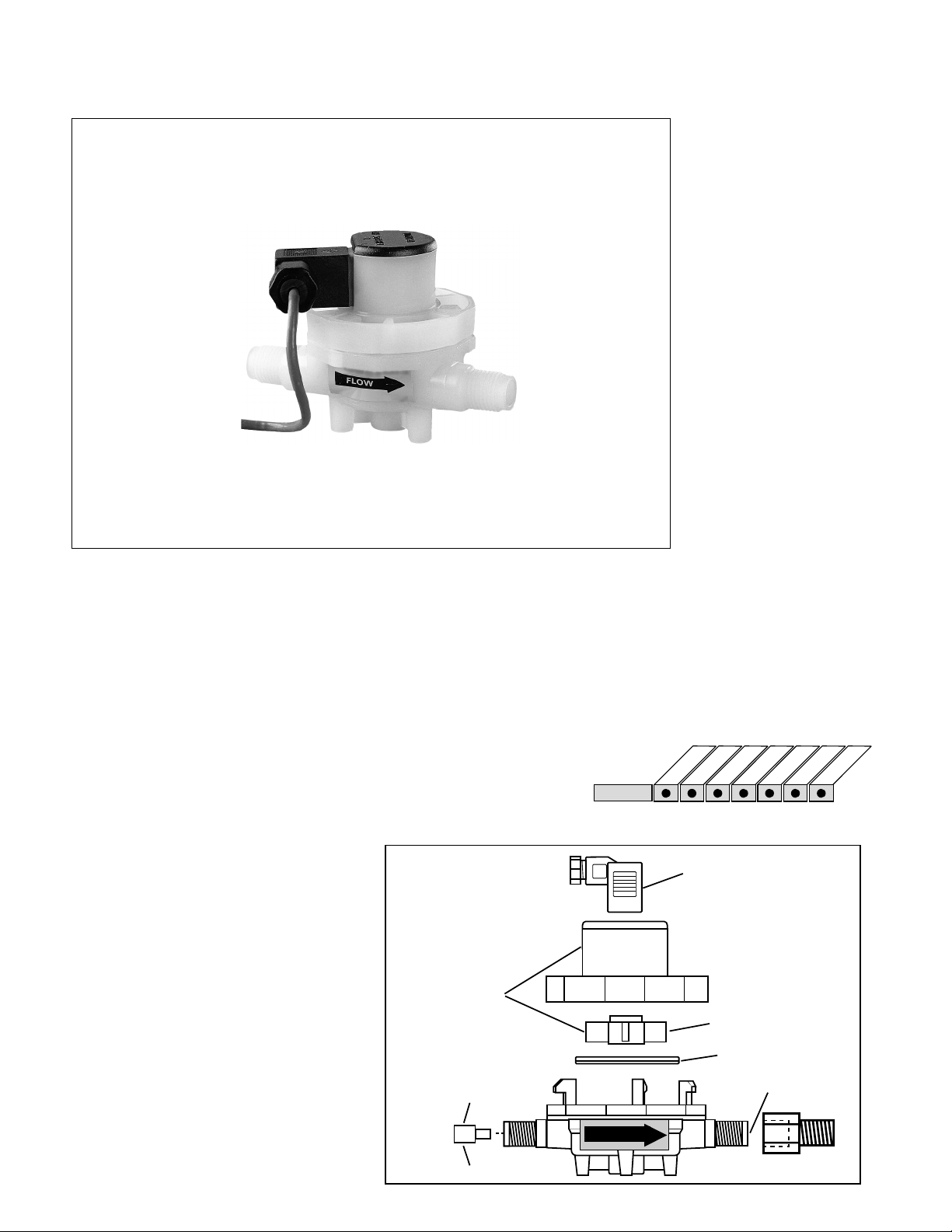
The +GF+ SIGNET 2507 Mini Flow
Sensor contains a free-running rotor that
is driven by the fluid flow. Within the
given measurement range, the rotational
speed of the rotor is proportional to the
fluid flow rate. Permanent magnets built
into the rotor trigger an electronic switch
in the top of the sensor creating a
square-wave output frequency proportional to flow rate. Both opaque and
transparent fluids can be measured from
0.2 to 20.0 centistokes.
Features
• Compact Assembly
• Simple Installation
• 1/4 in. Threaded
Connection
• Detachable Signal
Connector
• PVDF Construction
• Four Flow Ranges
• Between 0.5 to 12
lpm (0.1 to 3.2 gpm)
Application
• Fluid Dispensing
• Laboratory and
Clinical Wet Benches
• Chemical Dosing
• Batch Processes
Options
Technical Features
a) Removable, sealed electrical connection
b) PVDF body and rotor
c) 4-magnet rotor (fully encapsulated)
d) Viton quad-ring seal
e) Inserts for different flow ranges
f) G 1/4 or 1/4” NPT tubing or pipe con-
nection adapters included
28
b
Flow Inserts:
2 mm
3 mm
4 mm
e
a
c
d
f
FLOW
www.gfsignet.com
Page 2
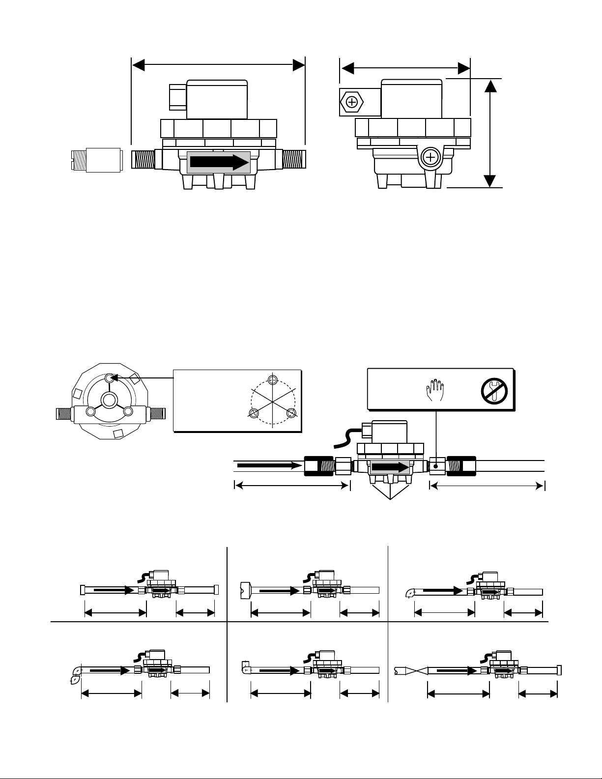
Dimensions
FLOW
100-150 mm (4-6 in.)
100-150 mm (4-6 in.)
FLOW
Pipe Fitting
Adapters
(included)
Hand
tighten
only!
Coupling
Pipe or
tubing
Mounting
tabs (3)
1-1/4 in.G 1/4
Adapter (2 included)
95 mm/3.74 in.
FLOW
68 mm/2.7 in.
65 mm/
2.6 in.
Installation
• The sensor may be installed in any position, although
horizontal flow is recommended with the top of the sensor
pointing upward. If the sensor is not installed horizontally, the linearity error may be greater in the lower part
of the sensor's measurement range. Mounting tabs are
provided for surface mounting using #8 or M4 selftapping screws (customer supplied). See drawings below
for mounting tab hole pattern specifications.
• Install sensor with the arrow pointing in the direction of
flow.
Mounting tabs (3),
#8 or M4 self-tapping
screws required
(customer supplied)
32.5 mm (1.28 in.)
bolt circle
• Always maximize distance between the sensor
and pump source. Never install immediately
downstream of valves, fittings etc. For optimum
performance, a straight flow run of at least 100 to
150 mm (4 to 6 in.) should be provided before
and after the sensor.
• Two pipe fitting adapters (included) convert the
sensor's G1/4 in. straight threads to 1/4 in. NPT
pipe threads for use with common pipe fittings.
Flange
2 x 90° Elbow
www.gfsignet.com
Inlet
Outlet
FLOW
10x I.D. 5x I.D.
FLOW
25x I.D. 5x I.D.
Reducer
15x I.D. 5x I.D.
2 x 90° Elbow
3 dimensions
40x I.D. 5x I.D.
FLOW
90° Elbow
FLOW
20x I.D. 5x I.D.
Valve/Gate
FLOW
FLOW
50x I.D. 5x I.D.
29
Page 3

Wiring
‡ SIGNET
• Use 2-conductor shielded cable for
cable extensions up to
300 m (1000 ft).
• Cable shield must be maintained
through cable splice.
• +GF+ SIGNET Intelek-Pro, use 2536
input card setting
• Refer to your instrument manual for
specific wiring details.
Other Brands
• Pull-up resistor required (10 kΩ
recommended).
• Use 2-conductor shielded cable for
cable extensions up to
300 m (1000 ft).
• Cable shield must be maintained
through cable splice.
2507
Sensor Power:
5 to 24 VDC
(Black wire)
Sensor Signal Output
(Red wire)
1
Wiring to +GF+ SIGNET Instrument
Sensor
ground
2
(Silver wire)
Disregard ground
symbol on connector
Max cable length:
Black
Power
Red
Frequency Input
Shield
Ground
300 m (1000 ft.)
Detachable
connector (side view)
Technical Data
FLOW
General
Flow Range:
-2V sensor: 400 to 2800 mL/m (0.105 to 0.740 U.S. gpm)
-3V sensor: 700 to 4200 mL/m (0.185 to 1.123 U.S. gpm)
-4V sensor: 1300 to 6000 mL/m (0.343 to 1.585 U.S. gpm)
-6V sensor: 3200 to 12000 mL/m (0.845 to 3.170 U.S. gpm)
Linearity: ±0.25% of full range
Repeatability: ±0.25% of full range
Viscosity range: 0.2 to 20.0 centistokes
Pipe connections: G 1/4 in. ports, 1/4 in. NPT (male)
pipe adapters (2 included)
Cable length: 7.6m (25 ft.), can splice up to
300 m (1000 ft.) max.
Sensor
Model
-2V
-3V
-4V
-6V
Cable type: 2-conductor shielded twisted-
pair (22 AWG) (SIGNET 5523-0222)
Shipping Weight: 0.59 kg (1 .3 lbs.)
Wetted Materials
• Housing: PVDF
• Flow insert: PTFE
• Quad ring seal: Viton
®
Max. pressure/temperature:
• 5.5 bar @ -30°C (80 psi @ -22°F)
• 5.5 bar @ 24°C (80 psi @ 75°F)
• 3 bar @ 120°C (45 psi @ 248°F)
• Rotor: PVDF
• Pipe thread adapters: PVDF
• Suitable for clean fluids only
Electrical
Power: 5 to 24 VDC @ 10 mA max from +GF+ SIGNET
instrument or external supply
Output type: Open-collector transistor, 10 mA max. sink
Pressure Drop Across Sensor vs. Flow Rate
PSI
BAR
1.50
21.76
18.13
14.50
10.88
7.25
3.63
1.25
1.00
0.75
0.50
0.25
-2V
-3V
-4V
-6V
K-Factors
Flow
Insert
2 mm
3 mm
4 mm
None
psibar
100
6.9
80
5.5
60
4.
1
40
2.8
20
1.4
0
-40 0 40 80 120 160 200 240 280
-40 -18 4 27 49 71 93 116 138
Pulses Per
U.S. Gallon
5685
3308
2316
1249
Pulses Per
Liter
1502
874
612
330
Pulses Per
mL
1.502
0.874
0.612
0.330
°F
°C
30
02040607080
Flow rate (%) of full scale
www.gfsignet.com
Page 4

Ordering Information
Mfr. Part No. Code Description
3-2507.100-2V 198 801 732 Mini-Flow Sensor, 2mm insert
3-2507.100-3V 198 801 733 Mini-Flow Sensor, 3mm insert
3-2507.100-4V 198 801 734 Mini-Flow Sensor, 4mm insert
3-2507.100-6V 159 000 264 Mini-Flow Sensor, 6mm inlet, no insert
Accessories
Mfr. Part No. Code Description
3-2507.080-2 159 000 254 Rotor, 2507
3-2507.080-3 159 000 255 Quad Ring, 2507
3-2507.080-5 159 000 256 DIN Connector, 2507
3-2507.081-2 198 801 502 2 mm Insert
3-2507.081-3 198 801 503 3 mm Insert
3-2507.081-4 198 801 558 4 mm Insert
5523-0222 159 000 392 Cable, per foot
Engineering Specifications
• The sensor shall operate with a power input of 4.5 to 24 VDC @ 13 mA maximum.
• The sensor shall provide an output signal via an open-collector transistor sinking a maximum of 10 mA.
• Output shall be via a twisted pair, foil-shielded cable with drain wire.
Supplied cable shall be at least 7.6 m (25 ft) long, with a maximum allowable length of 300 m (1000 ft).
• Measurement accuracy and repeatability shall be ±0.25% of full range.
• The sensor shall be available in versions that accommodate nominal flow rates from:
-2V sensor: 400 to 2800 mL/m (0.105 to 0.740 U.S. gpm)
-3V sensor: 700 to 4200 mL/m (0.185 to 1 .123 U.S. gpm)
-4V sensor: 1300 to 6000 mL/m (0.343 to 1.585 U.S. gpm)
-6V sensor: 3200 to 12000 mL/m (0.845 to 3.170 U.S. gpm)
• The sensor body and rotor shall be made of polyvinylidene fluoride (PVDF) that shall accommodate up to 80
psi @ -30°C (-22°F) and 45 psi @ 120°C (248°F).
• The sensor body shall be constructed to allow easy access for inspecting and cleaning internal mechanical
parts without exposing electronic components.
• The sensor shall provide 0.25 in. NPT male fittings for attachment to rigid pipe or tubing.
• The flow sensor shall be
+GF+
SIGNET 2507 Mini Flow.
Viton® is a registered trademark of DuPont Dow Elastomers.
www.gfsignet.com
31
 Loading...