

Page 1
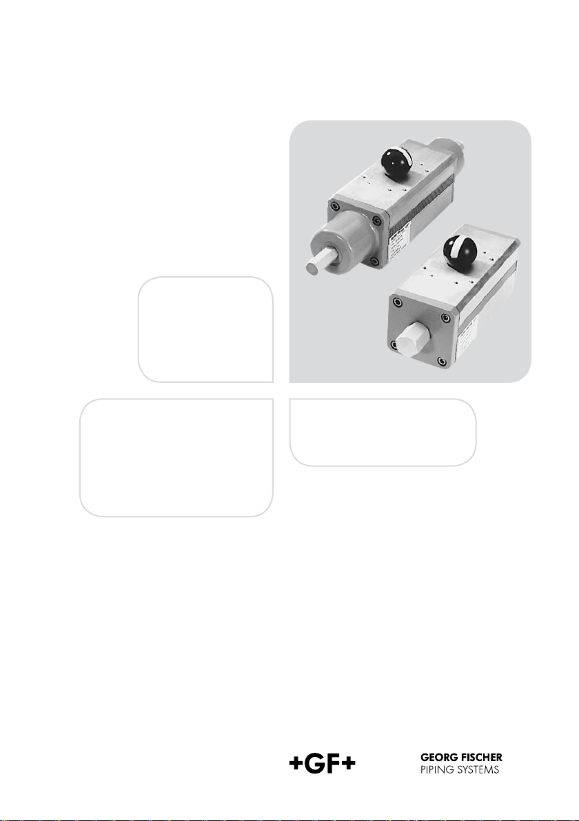
Instruction Manual
Pneumatic actuator
PA 30 – PA 90
25
Page 2

The technical data is not binding
and not an expressly
warranted characteristic of the
goods. It is subject to change.
Please consult our General
Conditions of Supply.
2
Page 3

Table of Contents
1. Introduction
2. General Information
2.1 Hazard notices
2.2 Abbrevations
3. EU declaration by manufacturer
4. Intended Use
5. Safety Tips
5.1 Due care required of the operator
5.2 Special hazards
5.3 Transport and storage
6. Technical Data
6.1 The Actuator
6.2 Torque characteristics
6.3 Direction of rotation of the actuator
6.4 Actuator Dimensions
7. Valve Components
7.1 Setting the End Stops
7.2 Stroke limiter «close»
7.3 Stroke limiter «open»
7.4 Setting the «close» position of
the butterfly valve Type 037
8. Installation of Supplementary Kits
9. Control Diagrams
10. Spare Part List
Page
4
4
5
6
7
10
15
18
19
20
3
Page 4
1. Introduction
This instruction manual contains the technical data
as well as instructions for installation, operation
and maintenance of the pneumatic actuators type
PA 30 - PA 90.
2. General Information
2.1 Hazard notices
Hazard notices are used in this manual to warn you
of possible injuries or damages to property. Please
read and abide by these warnings at all times!
Warning symbols
Danger
Warning
Caution
Meaning
Imminent acute danger!
Failure to comply could result in death or extremely
serious injury.
Possible acute danger!
Failure to comply could result in serious injury.
Dangerous situation!
Failure to comply could lead to injury or damage to
property.
4
Page 5
2.2 Abbreviations
DA Double acting
FC Fail-safe to close
FO Fail-safe to open
DN Dimension
The Planning Fundamentals referred to in the text
may be obtained from your sales company or on
the Internet at www.piping.georgfischer.com.
3. EU declaration by manufacturer
The manufacturer: Georg Fischer Piping Systems
Ltd, 8201 Schaffhausen (Switzerland), declares
that the pneumatic actuators type PA 30 - PA 90
are not machines ready for use as defined by the EU
machine guideline and cannot therefore comply fully
with the requirements of this guideline.
Commissioning of this actuator is only forbidden
until the conformity of the complete system in
which the valve and actuator are fitted corresponds
with the specified EU guidelines 98/37/EU.
Employed EU guidelines:
98 / 37 EG machine guideline
Modifications to the actuator and to control assemblies installed, which influence the technical data
specified in this instruction manual and use for
the intended purpose, and therefore significantly
modify the actuator, invalidate this manufacturer
declaration.
Warning
5
Page 6
Warning
4. Intended Use
The descriptions and instructions in the following
apply to the pneumatic actuators:
Type PA 30 - PA 90 part-turn valve actuator
DA / FC / FO
When built into GF Piping Systems valves and connected to a system control, the purpose of these
actuators is to
• actuate fittings with a control pressure of 2.8 to
7 bar and up to a driving torque of 20 Nm, and
• depending on the type of pneumatic actuator,
double acting (type designation DA) or single
acting with spring for fail-safe to CLOSE (type
designation FC) or single acting for fail-safe to
OPEN (type designation FO),
• control these valves to the OPEN and CLOSED
positions via a built-in solenoid valve. The solenoid
valve must be either supplied ex GF Piping
Systems works or already mounted by the
customer,
• indicate these positions OPEN and CLOSED via
an electric signal to the system control, if the
actuator is equipped for this with the respective
sub assembly,
• enable control of these positions through manual
operation in case of failure in the compressed air
supply, if the actuator is equipped for this with the
respective subassembly.
The actuator is not intended for applications other
than those specified here.
Prohibited in particular are:
• control pressures above 7.5 bar,
• manual operation with forces higher than permit-
ted according to prEN12570 (maximum retention
forces for operation of valves),
6
Page 7
• operating solenoid valves and position feedback
units under water.
The actuator can only function properly if it has been
connected professionally as per the Control Diagrams on page 43 for double acting operation and
for failsafe OPEN or fail-safe CLOSE operation,
respectively.
If the information contained in these instructions is
not observed, the manufacturer cannot accept liability for the above products.
5. Safety Tips
5.1 Due care required of the operator
The pneumatic actuators described herein were
designed and manufactured with consideration to a
risk analysis and the respective harmonized European standards. They correspond to the latest technology and meet the mentioned prescribed safety
standards.
Warning
Safety on the job can, however, only be realized if
all the necessary measures have been taken. It is
therefore the responsibility of the system engineer
and the operator of such systems into which the
valve with pneumatic actuator has been built to plan
such measures and make sure they are carried out.
Warning
7
Page 8
Warning
The operator must make certain in particular that
• the valve with pneumatic actuator is only used as
it was intended for (see Section 3),
• the design parameters control air pressure and
voltage of electric subassemblies of the pneumatic
actuator, as indicated in the scope of order
and delivery, are true and accurate,
• the pneumatic actuator is only operated when
in perfect working condition and the safety devices
for the system supply of compressed air are
regularly checked to make sure they are in perfect
order,
• only qualifi ed and authorized personnel plan,
connect, and work with the actuator and that
employees are instructed periodically in job
safety matters according to the local regulations
– especially as pertaining to electrical equipment,
and
• personnel is familiar with and observes this in
struction manual and the information contained
herein.
5.2 Special hazards
Warning
8
Single acting, fail-safe OPEN and CLOSE (type
description FO and FC) pneumatic actuators have
pre-loaded springs that bring the valve into the
predefi ned position in case of compressed air loss.
Dismantling these actuators is dangerous and may
only be done by following special repair instructions
(avail able from GF Piping Systems!) and under the
guidance of a safety expert. Dismounting from the
valve may only be done in the safety position after
cutting off the compressed air supply.
Prior to any work on the electric subassemblies of
the pneumatic actuator, the electrical connections of
the control voltage should be disconnected.
Page 9

Any necessary live-line adjustments may only be
done with special insulated tools.
In addition, the operating instructions of the
manual valve must also be observed.
They are an integral component of this manual.
5.3 Transport and storage
The actuators must be handled, transported and
stored with care. Please note the following points:
• The actuators should be transported and/or
stored in their original unopened packaging.
• The actuators must be protected from harmful
physical infl uences such as dust, heat (humidity).
• It is important that the connections are neither
damaged by mechanical nor thermal influences.
• Prior to installation, the actuators should be
inspected for transport damages. Damaged
actuators must not be installed.
Warning
9
Page 10

6. Technical Data
0° 15° 30° 45° 60° 7 5° 90° 75° 60° 45 ° 30° 15° 0°
NmNm
0° 15° 30° 45° 60 ° 75° 90° 75° 60° 4 5° 30° 15° 0°
NmNm
6.1 The Actuator
Double acting
Control medium Neutral, non-aggressive gases,
Control pressure Single acting Double acting
Control connection R 1/8“ mit Namur-Platte R 1/4“
Control time ca. 0,5 – 4s
Control angle 90
Mode of operation – F
Permissible operating
temperature
Permissible humidity 0 – 95 %
or optical
Indicat
Housing material Aluminum hard anodized
* Standard series, for lower control pressures (min 2,8) special springs are available.
preferably slightly oily compressed air
min. 5,6* bar 5,6* bar
max. 7 bar 7 bar
°
ail-safe close (FC)
– Fail-safe open (FO)
– Double acting (DA)
– 10
°C to + 80
°C
6.2 Torque characteristics
Torque diagram proportional to angle of rotation
Single acting
10
Page 11

Torque chart [Nm] a ° = angle of rotation
Double acting Fail-safe close/
Dimension a ° 5.6 bar a ° 5.6 bar
0° 30.0 0° 30.0 2
PA 30
PA 35
A 40
P
PA 45
A 50
P
PA 55
PA 60
PA 65
PA 70
PA 75
PA 80
PA 85
PA 90
* Torque data for the function „fail safe to open“ only valid for the butterfly valve type 240, 241, 242 and ball valve type 230 - 235.
45° 15.0 50° 15.0 15.0 50° 15.0 16
90° 22.5
0° 45.0 0° 45.0 30.0 0° 37.5 42
45° 22.5
90° 34.0 90° 30.0 45.0 90° 33.8 24
0° 60.0 0° 60.0 40.0 0° 50.0 67
45° 30.0 50° 30.0 30.0 50° 30.0 30
90° 45.0 90° 40.0 60.0 90° 45.0 33
0° 90.0 0° 90.0 60.0 0° 78.0 95
45° 45.0 50° 45.0 45.0 50° 46.8 48
90° 68.0 90° 60.0 90.0 90° 70.
0° 12
45° 60.0 50° 60.0 60.0 50° 60.0 65
90° 90.0 90° 80.0 12
0° 180.0 0° 180.0 12
45° 90.0 50° 90.0 90.0 50° 90.0 92
90°
0° 240.0
45° 12
90° 180.0 90° 160.0 240.0
0° 360.0 0° 360.0 240.0
45° 180.0 50° 180.0 180.0 50° - 90° 270.0
0° 480.0 0° 480.0 32
45° 240.0
90° 360.0 90° 32
0° 72
45° 360.0 50° 360.0 360.0 50° - 90° 540.0 90° 480.0 72
0° 960.0 0° 960.0 640.0 0° - 45° 480.0 50° 480.0 480.0 50° - 90° 7
0° 1440.0 - - - - - 45° 72
90° 1080.0 - - - - - -
0° 192
45° 960.0 - - - - - 90° 1440.0 - - - - - -
135.0 90° 12
Fail-safe open
air
90° 20.0 30.0 90° 22.5 18
50° 22.5 22.5 50° 22.5 23
0.0 0° 120.0 120.0 0° 100.0 135
0.0 180.0 90° 135.0 95
0° 180.0 160.0 0° - -
0.0 50° 120.0 120.0 50° - -
90° 240.0 360.0 90° - -
50° 240.0 240.0 50° 240 250
0.0 480.0 90° 350 255
0.0 0° 720.0 480.0 0° - -
2
0.0 90° 640.0 960.0 90° - -
0.0 - - - - - -
0.0 - - - - - -
5.6 bar
spring
Fail-safe open *
a ° 5.6 bar
0.0
0.0 90° 90.0 67
0.0 0° 150.0 200
0.0 0° 400 510
0.0 90° - -
0° 25.0 35
90° - -
0° - -
air
2 49
5.6 bar
spring
11
Page 12

Double acting
Fail-safe close
Fail-safe open
6.3 Direction of rotation of the actuator
Valve closes Valve opens
6.4 Actuator Dimensions
all threads M5
12
FC/FO: PA 30 / 35 / 40 / 45
PA 50 / 55 / 60
DA: PA 30 / 35 /40 / 45
PA 50 / 55 / 60 / 65 / 70
FC / FO: PA 65 / 70 / 75 / 80
DA: PA 75 / 80 / 85 / 90
Page 13

Single acting (FC / FO)
Type D1
PA 30 F03/05 36/50 30 M5/6 1/8“ 10 276
PA 35 F05/07 50/70 35 M6/8 1/8“ 12 3
PA 40 F05/07 50/70 35 M6/8 1/8“ 12 370
PA 45 F05/07 50/70 55 M6/8 1/8“ 15 411 17 35 70
PA 50 F05/07 50/70 55 M6/8 1/8“ 15 42
PA 55 F07/10 70/102 70
PA 60 F07/10 70/102 70
PA 65 F010/12 10
PA 70 F12 1
PA 75 F14 140 100 M16 1/4“ – 82
PA 80 F14 140 100 M16 1/4“ – 918 36 – –
ype L5
T
mm
A 30 – 97 70 20,5
P
PA 35 – 104,5 77,5 20,5
PA 40 – 12
PA 45 – 139 96 25 2
PA 50 – 149 106 25 2
PA 55 – 161 118 25 2
PA 60 – 173 130 25
PA 65 32 191
PA 70 32 196
PA 75 32 22
PA 80 32 2
mm
H
mm
D2
mm
2/125 85 M10/12 1/8“ – 648 27 – –
25 85 M12 1/4“ – 663 27 – –
H1
mm
9 86 25 21 80,5 13 30 36 –
148 24 34 136,5 – – – 22
153 24 38 145 – – – 24
9 186 24 43 166 – – – 27
41 198 24 44 180 – – – 32
D3
mm
M8/10 1/8“ 19 452 22 35 70
M8/10 1/8“ 19 503 22 35 70
H2
mm
D4
mm
H3
mm
17,9 65,5 13 20 36 –
17,9 72 13 20 36 –
32 125 19 30 36 –
D5
mm
H4
mm
1 90 16 30 36 –
6 100,5 17 30 36 –
5 112 19 30 36 –
L
mm
H5
mm
L2
mm
11 35 70
26 14 35 70
14 35 70
3 17 35 70
4 36 – –
H6
mm
L3
mm
H7
mm
L4
mm
H8
mm
13
Page 14

Double acting (DA)
Type D1
PA 30 F03/05 36 2
PA 35 F03/05 42 30
PA 40 F03/05 42 30
PA 45 F05/07 50 35 M6/8 1/8“ 12 2
PA 50 F05/07 50 35 M6/8 1/8“ 12 2
PA 55 F05/07 70 55 M6/8 1/8“ 15 279
PA 60 F05/07 70 55 M6/8 1/8“ 15 341 17 35 70
PA 65 F07/10 102 70
PA 70 F07/10 102 70
PA 75 F10/12 1
PA 80 F12 1
PA 85 F14 140 100 M16 1/4“ – 555 36 – –
PA 90 F14 140 100 M16 1/4“ – 581 36 – –
Type L5
mm
P
A 30 – 87 60 25
PA 35 – 92
PA 40 – 97 70 20,5
PA 45 – 104,5 77,5 20,5
PA 50 – 12
PA 55 – 139 96 25 2
PA 60 – 149 106 25 2
PA 65 – 161 118 25 2
PA 70 – 173 130 25
PA 75 32 191
PA 80 32 197
PA 85 32 22
PA 90 32 2
mm
H
mm
D2
mm
25 85 M10/12 1/8“ – 416 27 – –
25 85 M12 1/4“ – 466 27 – –
H1
mm
,7 65,7 25 12,5 60 13 20 36 –
9 86 25 21 80,5 13 30 36 –
148 24 34 137 – – – 22
153 24 38 145 – – – 24
9 186 24 43 166 – – – 27
41 198 24 44 180 – – – 32
D3
mm
5 M5/6 1/8“ 9 177 9 35 70
M5/6 1/8“ 10 190 11 35 70
M5/6 1/8“ 10 198 11 35 70
M8/10 1/8“ 19 350 22 35 70
M8/10 1/8“ 19 381 22 35 70
H2
mm
D4
mm
H3
mm
12 55,5 10 20 36 –
17,9 65,5 13 20 36 –
17,9 72 13 20 36 –
32 124 19 30 36 –
D5
mm
H4
mm
1 90 16 30 36 –
6 100,5 17 30 36 –
5 112 19 30 36 –
L
mm
H5
mm
L2
mm
35 14 35 70
50 14 35 70
17 35 70
H6
mm
L3
mm
H7
mm
L4
mm
H8
mm
14
Page 15

7. Valve Components
Butterfly valve type 240 / 241 / 242
Dimension DN50 - DN300
Ball valve type 230 (replaces Type
208) Dimension DN50 - DN150
Butterfly valve type 037 / 038
Dimension DN50 - DN300
!
"
§
!
!
"
§
!
Actuator PA 30–PA 90
"
Inermedia part with screws
§
Butterfly valve
$
Ball valve
"
$
15
Page 16

7.1 Setting the End Stops
7.2 Stroke limiter «close»
(max. 10 ° R, 0 – 10 ° R)
a) Make sure the springs are in the position of
rest; the groove in the shaft (part 1) should be
in the same position as in the diagram. Also
check that there is no compressed air in the
bore «D».
b) Unscrew the special nut (part 2).
c) Put compressed air in the bore «D».
d) With a screwdriver, turn the screws (part 3) in
a counterclockwise direction until the desired
setting is reached.
e) Release the compressed air from the bore «D».
f) Check the setting and, if necessary, repeat the
procedure from Step c).
g) Replace the special nut (part 2) and press the
O-ring seals in the corresponding grooves
(part 4).
16
Page 17

7.3 Stroke limiter «open»
(max. 10° R, 90 – 80° R)
a) Make sure the springs are in the position of
rest; the groove in the shaft (part 1) should be
in the same position as in the diagram. Also
check that there is no compressed air in the
bore «D».
b) Unscrew the special nut (part 2).
c) With a screwdriver, turn the screws (part 3) in
a clockwise direction until the desired setting
is reached.
d) Put compressed air in the bore «D» and check
that the pistons (part 5) hit against the screws
(part 3).
e) Replace the special nut (part 2) and press the
O-ring seals in the corresponding grooves
(part 4).
Attention Please: Regulating the stroke limiter for
the two pistons can only be done in one direction
(close or open)!
7.4 Setting the «close» position of the
butterfly valve type 037
Warning
In the «close» position of the butterfly valve, the disc
is not exactly vertical to the pipe axis. The deviation
can be seen in the table below.
36
DN mmd
50 63 – 16
65 75 4 16
80 90 4 16
100 110 5 18
5 140 5 17
12
150 160 6 17
200 22
250 2
300
a–b
mm
mm
mm
5 6 17
80 0 25
315 – 25
37
b
Open
G/2
a
a–b
17
Page 18

8. Installation of
Supplementary Kits
Namur connecting plate
(for 5/2 way pilot valve)
3/2 way pilot valve PV 93
230 V ~ 199 190 263
115 V ~ 199 190 264
24 V = 199 190 265
24 V ~ 199 190 266
4/2 way pilot valve type 470
230 V AC / DC 199 190 302
115 V AC /
24 V AC / DC 199 190 304
DC 199 190 303
199 190 275
18
Namur mounting flange 199 190 281
2 mechanical auxiliary
switches
2 inductive auxiliary switches
with luminous diode
2 inductive auxiliary switches
with luminous diode
2 inductive auxiliary switches Namur 5 - 2
2 auxiliary switches EExd 250
Additional 2 auxiliary switches
with gold contact
The connection diagram is printed onto the limit switch box.
mech. 250
NPN 10...30 V
PNP 10...30 V/
Vp / 10 A 199 190 282
/ 0.1 A 199 190 283
0.1 A 199 190 284
4 V 199 190 285
Vp / 5 A 199 190 286
30 V = max.
1-100 mA
199 190 287
Page 19

9. Control Diagrams
A B
4 2
5 1 3
R P
A B
4 2
5 1 3
R P S
Double acting with
Namur 5/2 way valve
Single acting with
Namur 5/2 way v
alve
B
2
1 3
P S
Single acting with
3/2 way v
alve
19
Page 20

10. Spare Part List
Actuator types PA 30 – PA 90
Type FC / FO DA FO *
PA 30 198 800 757 198 800 737 198 811 025
A 35 198 800 037 198 800 758 198 811 026
P
A 40 198 800 728
P
PA 45 198 800 039 198 800 040 198 811 028
A 50 198 800 729
P
PA 55 198 800 041 198 800 042 198 811 030
PA 60
PA 65 198 800 043 198 800 044 -
PA 70 198 800 731 198 800 735 198 811 198
PA 75 198 800 045 198 800 046 -
PA 80 198 800 047 198 800 048 -
PA 85 - 198 800 050 -
PA 90 - 198 800 051 -
* only for valve types 230, 231, 232, 233, 234, 235, 240, 241and 242.
** only for valve type 240.
198 800 730 198 800 734 -
198 800 759 198 811 027
198 800 733 198 811 029
-
**
20
Visual position indicator
198 806 672
PA 30 / PA 35 (FC / FO); PA 30 – PA 45 (DA)
198 806 459
– PA 80 (FC / FO); PA 50 – PA 80 (DA)
PA 40
Page 21

Assignment of actuators and intermediate parts for
types 230-235
FC
DN
mm
65 PA 30 198 800 757 198 000 595
80 PA 35 198 800 037 198 000 596
100 PA 40 198 800 7
150 PA 40 198 800 72
FO
DN
mm
65 PA 30 198 811 0
80 PA 35 198 811 02
100 PA 40 198 811 02
150 PA 40 198 811 02
DA
DN
mm
65 PA 35 198 800 758 198 000 595
80 PA 40 198 800 759 198 000 595
100 PA 45 198 800 040 198 000 599
150 PA 45 198 800 040 198 000 599
Type Actuator Intermediate
part
8 198 000 599
2
8 198 000 599
Type Actuator Intermediate
part
5 198 000 595
2
6 198 000 596
7 198 000 599
7 198 000 599
Type Actuator Intermediate
part
21
Page 22

Assignment of actuators and intermediate
parts for types 240, 241, 242
FC
DN mmType Actuator Intermediate
50 PA 30 198 800 757 198 000 595 198 000 630
65 PA 30 198 800 757 198 000 595 198 000 630
80 PA 35 198 800 037 198 000 596 198 000 631
100 PA 40 198 800 7
125 PA 45 198 800 039 198 000 597 198 000 629
PA 50 198 800 729
150
200 PA 55 198 800 041 198 000 598 198 000 627
50 PA 65 198 800 043 198 000 730 -
2
300 PA 70 198 800 731 198 000 730 -
FO
DN mmType Actuator Intermediate
50 PA 30 198 811 0
65 PA 30 198 811 025
80 PA 35 198 811 026
100 PA 40 198 811 027
125 PA 45 198 811 028
150 PA 50 198 811 029
200 PA 55 198 811 030 198 000 598 198 000 627
50 PA 70 198 811 198 198 000 730 -
2
300 PA 70 198 811 198 198 000 730 -
part
198 000 600 198 000 628
28
198 000 599 198 000 625
part
25
198 000 595 198 000 630
198 000 595 198 000 630
198 000 596 198 000 631
198 000 600 198 000 628
198 000 597 198 000 629
198 000 599 198 000 625
Intermediate
part with
manual
emergency
operation
Intermediate
part with
manual
emergency
operation
22
Page 23

DA
DN mmType Actuator Intermediate
part
50 PA 35 198 800 758 198 000 595 198 000 630
65 PA 35 198 800 758 198 000 595 198 000 630
80 PA 40 198 800 759 198 000 595 198 000 630
100 PA 45 198 800 040 198 000 600 198 000 6
125 PA 50 198 800 733 198 000 600 198 000 62
150 PA 55 198 800 042 198 000 600
200 PA 55 198 800 042 198 000 600
250 PA 65 198 800 044 198 000 731 -
300 PA 70 198 800 735 198 000 731 -
Intermediate
part with
manual
emergency
operation
198 000 625
198 000 625
8
2
8
23
Page 24

Assignment of actuators and intermediate parts for
types 037/ 038
FC / FO
DN mmType Actuator Intermediate
50 PA 30 198 800 757 198 000 382
PA 30 198 800 757 198 000 382
65
PA 35 198 800 037 198 000 383
80
100 PA 40 198 800 72
125 PA 45 198 800 039 198 000 386
150 PA 50 198 800 72
200 PA 55 198 800 730 198 000 389
A 60 198 800 730 198 000 391
250 P
300 PA 70 198 800 731 198 000 392
DA
DN mmType Actuator Intermediate
50 PA 35 198 800 758 198 000 382
PA 35 198 800 758 198 000 382
65
PA 35 198 800 758 198 000 384
80
100 PA 45 198 000 040 198 000 385
5 PA 45 198 800 040 198 000 387
12
150 PA 50 198 800 042 198 000 388
A 60 198 800 734 198 000 390
200 P
A 65 198 800 044 198 000 391
250 P
300 PA 70 198 800 735 198 000 393
part
8 198 000 385
9 198 000 388
part
24
Page 25

Australia
George Fischer Pty Ltd
erwood NSW 2210 Australia
Riv
Phone +61(0)2/9502 8000
australia.ps@georgfischer.com
www.georgefischer.com.au
Austria
Georg Fischer
Rohrleitungssysteme GmbH
3130 Herzogenburg
Phone +43(0)2782/856 43-0
austria.ps@georgfischer.com
www.georgfischer.at
/ Luxembourg
Belgium
Georg Fischer NV/SA
1070 Bruxelles/Brüssel
Phone +32(0)2/556 40 20
be.ps@georgfischer.com
www.georgfischer.be
Brazil
George Fischer Ltda
04795-100 São Paulo
Phone +55(0)11/5687 1311
br.ps@georgfischer.com
China
g Fischer
Geor
Piping Systems Ltd Shanghai
Pudong, Shanghai
Phone +86(0)21/58 13 33 33
china.ps@georgfischer.com
www.cn.piping.georgfischer.com
Denmark
Georg Fischer A/S
2
630 Taastrup
Phone +45 (0)70 22 19 75
info.dk.ps@georgfischer.com
www.georgfischer.dk
France
Georg Fischer SAS
9593
2 Roissy Charles de Gaulle Cedex
Phone +33(0)1 41 84 68 84
fr.ps@georgfischer.com
www.georgefischer.fr
Germany
Georg Fischer GmbH
73095 Albershausen
Phone +49(0)7161/302-0
info.de.ps@georgfischer.com
www.georgfischer.de
India
Georg Fischer Piping Systems Ltd
400 076 Mumbai
Phone +91 224007 2001
in.ps@georgfischer.com
www.georgfischer.in
201319
/ Iceland
Italy
Georg Fischer S.p.A.
0063 Cernusco S/N (MI)
2
Phone +3902/921 861
it.ps@georgfischer.com
www.georgfischer.it
Japan
Georg Fischer Ltd
556-0011 Osaka,
Phone +81(0)6/6635 2691
jp.ps@georgfischer.com
www.georgfischer.jp
Korea
Georg Fischer Piping Systems
Guro-3 dong, Guro-gu, Seoul, Korea
+82(0)2 2081 1450
Phone
Fax +82(0)2 2081 1453
kor.ps@georgfischer.com
Malaysia
Georg Fischer (M) Sdn. Bhd.
40460 Shah Alam, Selangor
Phone +60 (0)3-5122 5585
conne.kong@georgfischer.com
Mexico
Georg Fischer S.A. de C.V.
Apodaca, Nuevo Leon
CP66636 Mexico
+52 (81)1340 8586
Phone
Fax +52 (81)1522 8906
Middle East
George Fischer Piping Systems
Dubai, United Arab Emirates
Phone +971 4 289 41 20
gfdubai@emirates.net.ae
www.piping.georgfischer.com
Netherlands
Georg Fischer N.V.
8161 PA Epe
Phone +31(0)578/678 222
nl.ps@georgfischer.com
www.georgfischer.nl
Norway
Georg Fischer AS
1351 Rud
Phone +47(0)67 18 29 00
no.ps@georgfischer.com
www.georgfischer.no
Poland
Georg Fischer Sp. z o.o.
2-226 Warszawa
0
Phone +48(0)22/313 10 50
poland.ps@georgfischer.com
www.georgfischer.pl
Romania
Georg Fischer
Piping Systems Ltd
20257 Bucharest - Sector 2
0
Phone +40(0)21/230 53 80
ro.ps@georgfischer.com
Russia
Georg Fischer Piping Systems
Mosc
ow 125047
Tel. +7 495 258 60 80
ru.ps@georgfischer.com
Singapore
George Fischer Pte Ltd
5
28 872 Singapore
Phone +65(0)67 47 06 11
sgp.ps@georgfischer.com
www.georgefischer.com.sg
/ Portugal
Spain
Georg Fischer S.A.
2
8046 Madrid
Phone +34(0)91/781 98 90
es.ps@georgfischer.com
www.georgfischer.es
eden / Finland
Sw
Georg Fischer AB
12523 Älvsjö-Stockholm
Phone +46(0)8/506 775 00
info.se.ps@georgfischer.com
www.georgfischer.se
Switzerland
Georg Fischer
Rohrleitungssysteme (Schweiz) AG
201 Schaffhausen
8
Phone +41(0)52 631 30 26
ch.ps@georgfischer.com
www.piping.georgfischer.ch
Taiwan
Georg Fischer Piping Systems
San Chung City, Taipei Hsien
+886 2 8512 2822 Ext. 15
Phone
Fax +886 2 8512 2823
United Kingdom / Ireland
George Fischer Sales Limited
ventry, CV2 2ST
Co
Phone +44(0)2476 535 535
uk.ps@georgfischer.com
www.georgefischer.co.uk
/ Canada / Latin America / Caribbean
USA
Georg Fischer LLC
T
ustin, CA 92780-7258
Phone +1(714) 731 88 00
Toll Free 800/854 40 90
us.ps@georgfischer.com
www.us.piping.georgefischer.com
Export
Georg Fischer
Piping Systems (Switzerland) Ltd.
201 Schaffhausen
8
Phone +41(0)52-631 30 26
Fax +41(0)52-631 28 93
export.ps@georgfischer.com
www.piping.georgfischer.ch
700 278 066
GMST 6058 / 1,4 (12.07)
© Georg Fischer Piping Systems Ltd
CH-8201 Schaffhausen/Switzerland, 2007
52
Printed in Switzerland
 Loading...