

Page 1
Signet 2350 Temperature Sensor
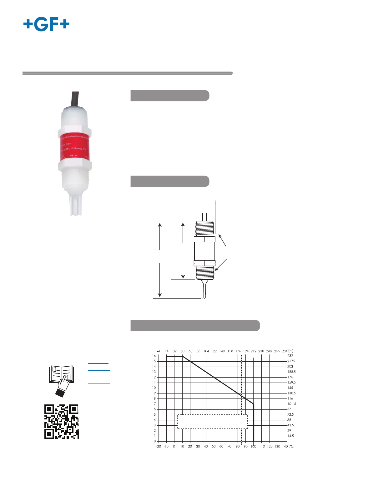
109 mm
(4.27 in.)
82 mm
(3.22 in.)
¾ in. NPT
30 mm
(1.18 in.)
Submersible installations
are limited to 85 °C (185 °F)
Application Limits
Pressure (bar)
Pressure (psi)
Temperature
*3-2350.090-1*
3-2350.090-1 Rev. 12 01/19
Description
The Signet 2350 Temperature Sensor has a one-piece injection molded PVDF
body that is ideal for use in high purity applications. It also outlasts metal sensors
in aggressive liquids and eliminates the need for costly custom thermowells.
These sensors are available with Digital (S3L) or fi eld-scaleable 4 to 20 mA output.
Dual threaded ends (3/4 in. NPT) allow submersion in process vessels, or in-line
installation with conduit connection. Integral adapters (sold separately) may be used
to create a compact assembly with fi eld mount style of the 9900 Transmitter.
Dimensions
English
Product Manual
• English
• Deutsch
• Français
• Español
• 中文
Pressure/Temperature Graph
Page 2

Warranty Information
Specifi cations
Refer to your local Georg Fischer Sales offi ce for the most
current warranty statement.
All warranty and non-warranty repairs being returned must
include a fully completed Service Form and goods must be
returned to your local GF Sales offi ce or distributor.
Product returned without a Service Form may not be
warranty replaced or repaired.
Signet products with limited shelf-life (e.g. pH, ORP, chlorine
electrodes, calibration solutions; e.g. pH buff ers, turbidity
standards or other solutions) are warranted out of box but not
warranted against any damage, due to process or application
failures (e.g. high temperature,
mishandling (e.g. broken glass,
chemical poisoning, dry-out) or
damaged membrane, freezing
and/or extreme temperatures).
Product Registration
Thank you for purchasing the Signet line of Georg Fischer
measurement products.
If you would like to register your product(s), you can now
register online in one of the following ways:
• Visit our website www.gfsignet.com.
Under Service and Support click on
Product Registration Form
• If this is a pdf manual (digital copy),
click here
Safety Information
1. Prior to installation or removal:
• Depressurize and vent system
• Drain below sensor level
2. Confi rm chemical compatibility before use.
3. Do not exceed maximum temperature/pressure specifi cations.
4. Wear safety goggles or faceshield during installation/service.
5. Do not alter product construction.
6. Dispose of properly; DO NOT INCINERATE!
Caution / Warning / Danger
Indicates a potential hazard. Failure to follow all warnings
may lead to equipment damage, injury, or death
Electrostatic Discharge (ESD) / Electrocution Danger
Alerts user to risk of potential damage to product by ESD,
and/or risk of potential of injury or death via electrocution.
Personal Protective Equipment (PPE)
Always utilize the most appropriate PPE during
installation and service of Signet products.
Pressurized System Warning
Sensor may be under pressure, take caution to vent
system prior to installation or removal. Failure to do so
may result in equipment damage and/or serious injury.
General
Compatibility ......................... Signet 8900 Multi-Parameter Controller
Signet 9900 Transmitter
9950 Dual Channel Transmitter
Wetted material .................... PVDF
Measurement range
In-line installation .................. -10 °C to 100 °C (14 °F to 212 °F)
Submersible installation........ -10 °C to 85 °C (14 °F to 185 °F)
Response time, τ .................. 10 seconds
Process connection .............. 3/4 in. NPT male thread
Rear connection ................... 3/4 in. NPT male thread
Cable type ............................ 3 cond + shield, 22 AWG
Standard cable length........... 4.6 m (15 ft)
Shipping weight .................... 0.22 kg (0.5 lb)
Electrical
Power requirements
3
L) models ..................... 5 VDC ±10%, <1.5 mA
(S
4 to 20 mA models ............ 12-24 VDC ±10%
Short circuit & reverse polarity protected
Digital (S
3
L) output ................ Serial ASCII, TTL level 9600 bps
Accuracy ........................... ±0.5 °C (±0.9 °F)
Repeatability ..................... ±0.1 °C (±0.2 °F)
Resolution ......................... 0.01 °C (0.02 °F)
Update rate ....................... <100 ms
4 to 20 mA output
Accuracy ........................... ±32 μA
Repeatability ..................... ±0.1 °C (±0.2 °F)
Resolution ......................... <5 μA
Factory Span..................... 0 °C to 100 °C, fi eld-scaleable.
Max loop impedance ......... 50 Ω @ 12 V
325 Ω @ 18 V
600 Ω @ 24 V
Update rate ....................... <100 ms
Environmental
Relative humidity............... 0 to 95% (Non-condensing)
Storage temperature ......... -55 °C to 100 °C (-67 °F to 212 °F)
Standards & Approvals
CE
RoHS Compliant
Manufactured under ISO 9001 for Quality, ISO 14001
for Environmental Management and OHSAS 18001 for
Occupational Health and Safety.
China RoHS (Go to www.gfsignet.com for details)
Declaration of Conformity according to FCC Part 15.
This device complies with Part 15 of the FCC rules.
Operation is subject to the following two conditions:
(1) This device may not cause harmful interference, and,
(2) This device must accept any interference received,
including interference that may cause undesired operation.
Hand Tighten Only
Overtightening may permanently damage product threads
and lead to failure of the retaining nut.
Do Not Use Tools
Use of tool(s) may damage product beyond repair and
potentially void product warranty.
2
Signet 2350 Temperature Sensor
Page 3
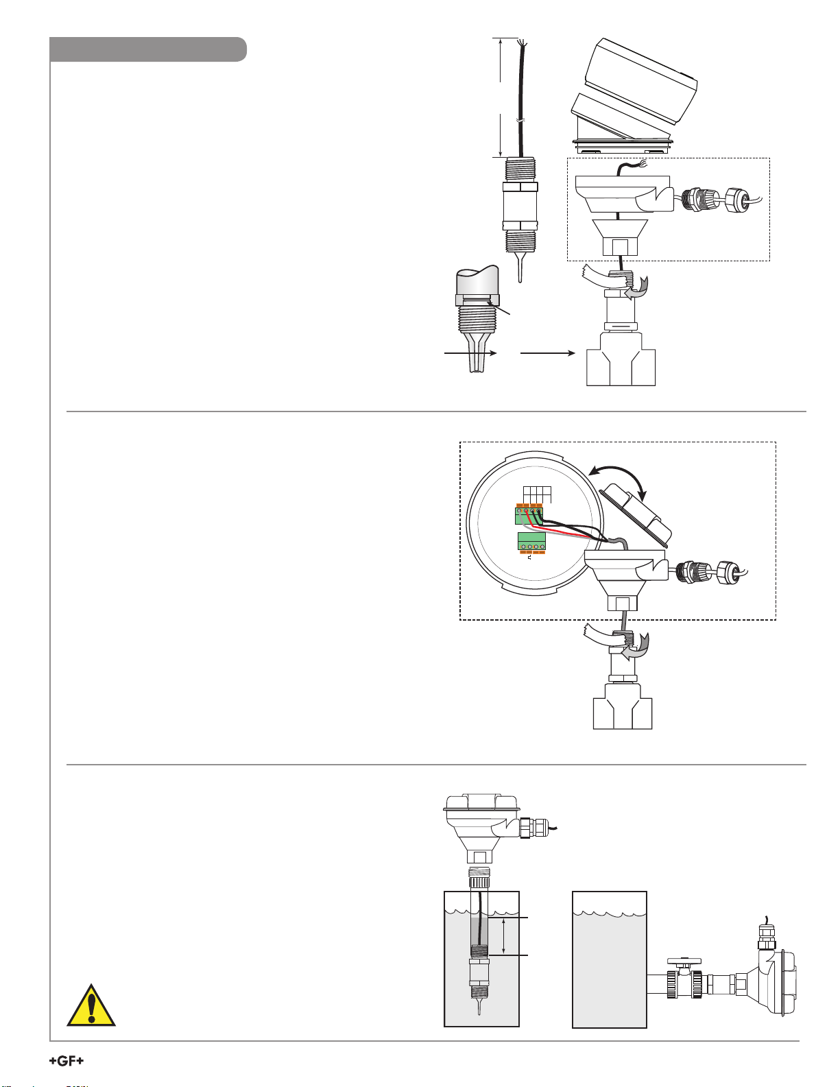
Installation
*
3-8052
Integral mount kit
3-9900
3-9900.396
Angle Adjustment Adapter Kit
*Customer supplied extension cable
must not exceed 305 m (1000 ft.)
4-20
mA
FREQ/
DATA
WHT WHT
BLU BLK
N/C RED
SHIELD
SENSOR
INPUT
*
SHIELD
–
+
FREQ/
DATA
3-8052-1
Integral junction box,
3/4 in. NPT
*Customer supplied extension cable
must not exceed 305 m (1000 ft.)
The compact integral assembly can be installed using the
following directions:
2350-1 Integral Assembly Sensor Modifi cation
• Modify sensor part number 3-2350-1 per fi gure 1.
• Apply sealant or PTFE tape to the process connection threads
per fi gure 2, after inspecting threads to ensure integrity. Do not
install a sensor with damaged threads.
• Thread the sensor into the 3-8052 mounting kit.
• Tighten the sensor 1½ turns past fi nger tight into the process
connection.
• Make sure the fl ow alignment indicator is in correct position in
the pipe. Damage to the sensor tip can occur if the sensor tip is
installed improperly.
• Install
9900 Transmitter
(refer to 9900 manual for wiring information).
• The 3-8052 Integral kit includes:
• 3/4 in. NPT process connection
• 3-9000.392-1 liquid tight connector, 1/2 in. NPT
2350-3 In-line Remote Assembly
The optional 3-8052-1 Integral Junction box with ¾ in. process
connection off ers a convenient terminal point to extend the 2350
cable over distances greater than 4.6 m (15 ft).
• The kit includes:
• ¾ in. NPT process connection
• Conduit base and cap with junction terminals
• 3-9000.392-1 liquid tight connector, ½ in. NPT
152 mm
(6 in.)
Figure 1
Align with
flow stream
Flow
Figure 2
To extend the wires longer than 4.6 m (15 ft):
• Modify sensor 3-2350-1 or 3-2350-3 as described in fi gure 1.
• Terminate the three wires to the terminal board located in the
cap assembly.
• Add customer-supplied wire to extend the cable.
• Terminate to the transmitter or the 4 to 20 mA input device.
• Apply sealant or PTFE tape to the process connection threads
per fi gure 3, after inspecting threads to ensure integrity.
DO NOT install a sensor with damaged threads.
• Tighten the sensor 1½ turns past fi nger tight into the process
connection.
2350-1 or 2350-3 Submersible Installation
• Use the 2350-1 or 2350-3 sensor with 4.6 m (15 ft) cable.
• Mount the sensor to an extension pipe or watertight conduit
using thread sealant.
• Use a cable gland at the top of the extension to prevent
moisture intrusion/accumulation inside the pipe.
• For additional defense against possible accumulation of
condensation at the back seal area of the sensor, fi ll the lower
75 mm to 100 mm (3 in. to 4 in.) of conduit or extension pipe
with a fl exible sealant such as silicone.
CAUTION!
The fl uid temperature must not exceed 85 °C (185 °F)
in submersible installations.
NOTE:
The 8050-1 or the 8052-1 junction
boxes can be useful accessories for this
installation option.
MXQFWLRQER[UHFRPPHQGHG
Fill with
3 to 4 in.
of sealant
Figure 3
Signet 2350 Temperature Sensor
3
Page 4

+
-
3-8052
3-8050.521
Loop Input +
4 to 20 mA
loop monitor
Power Supply
DC 12 - 24 V
Black (Loop +)
Optional
Earth Ground
Loop Input -
Shield
White (Loop - )
Red
Wiring
Digital (S3L) Wiring
• All models of the 2350 provide Digital (S3L) output when
powered with 5 VDC.
• Connecting the SHIELD to a direct Earth ground may
reduce electrical noise interference.
• The maximum Digital (S
the instrument to which the sensor is connected. Consult
the instrument manual for details.
• Connect the 2350 cable directly to Digital (S3L)
I/O terminals.
3
L) cable length is dependent upon
3-8052
3-9900
3
S
L connector
Optional
Earth ground
SHLD
GND
DATA
V+
Shield
White
Red
Black
3-8900
I/O Module Connector
I/O Module 3-8900.401-X
+5VDC (Black)
Frequency
Input
Freq. Input (Red)
1
GND (Shield)
+5VDC (Black)
Frequency
Input 2
Freq. Input 2 (Red)
OR
S3L
Input
S3L
Input
1
2
GND (White/Shield)
+5VDC (Black)
GND (White/Shield)
Analog Output 1
(if applicable)
Analog Output 2
(if applicable)
3
S L (Red)
3
S L (Red)
3-8900.621C
1
2
3
4
5
6
7
8
9
10
11
+
-
12
13
+
-
14
White
Red
Black
White
Black
Red
Shield
INPUT
SENSOR
WHT WHT
4-20
BLU BLK
N/C RED
mA
SHIELD
FREQ/
DATA
+
SHIELD
–
FREQ/
DATA
3-8052-1
3-9950
3
S
L connector
Black
White
Shield
No connection
X
CH2 CH1
Loop
Loop
FREQ
DATA
FREQ
GND
DC POWER
+V
+V
+V
FREQ
DATA
GND
4 to 20 mA Loop Wiring
• The 2350-3 provides a 4 to 20 mA loop output when powered with 12 to 24 VDC.
• Connecting the SHIELD to a direct Earth ground may reduce electrical noise interference.
• Red wire is not used, do not remove the heat shrink. See 4 to 20 mA Span Adjustment, page 5.
Current Loop With No Junction Box
Current Loop With Junction Box
Black
Power Supply
DC 12 - 24 V
+
-
• When the 2350 includes a
junction box, connect the
2350 terminals to any Digital
(S3L) I/O port as shown.
WHT WHT
4-20
BLU BLK
N/C RED
mA
SHIELD
FREQ/
DATA
SENSOR
INPUT
SHIELD
+
–
FREQ/
DATA
• Connect the 2350 cable directly to a loop device as shown.
4
Signet 2350 Temperature Sensor
Loop Input
Loop Input
White
+
-
3-8052-1
• When the 2350 includes a junction box, connect the 2350
terminals to a loop device as shown.
Page 5

+
-
3-8052
3-8050.521
Loop Input +
4 to 20 mA
loop monitor
Power Supply
DC 12 - 24 V
Black (Loop +)
Optional
Earth Ground
Loop Input -
Shield
White (Loop - )
Red
4 to 20 mA Span Adjustment
The 4 to 20 mA endpoint values are independent of one another and may be adjusted in the fi eld. For example, to reduce the
20 mA endpoint value from the factory setting of 100 °C, but to allow the 4 mA endpoint to remain at 0 °C, perform only the steps
listed below.
NOTE: The RED wire, which is not connected during normal 4 to 20 mA operation, assumes an important role in the following
procedures.
WARNING!
Not protecting the red wire may cause the 4 to 20 mA
span to be reset.
To adjust the 4 mA endpoint in the fi eld:
• Carefully remove the heat shrink tube protecting the red wire.
• Expose the sensor to the temperature desired to correspond with 4 mA
-10 °C to 100 °C (submersible: -10 °C to 85 °C).
(Be sure to allow suffi cient time for the sensor to reach equilibrium.)
• With power applied as described on page 4, connect the RED wire to the WHITE wire for 15 seconds.
(After about 10 seconds the output will drop to 3.6 mA and remain there until the RED wire is disconnected.)
• Disconnect the RED wire from the WHITE wire; the 4 mA endpoint has been adjusted.
• NOTE: The output will act as a switch if the 4 and 20 mA endpoints are set very near to the same value.
To adjust the 20 mA endpoint in the fi eld:
• Expose the sensor to the temperature desired to correspond with 20 mA -10 °C to 100 °C (submersible: -10 °C to 85 °C).
(Be sure to allow suffi cient time for the sensor to reach equilibrium to this temperature.)
• With power applied as described in on page 4, connect the RED wire to the BLACK wire for 15 seconds.
(After about 10 seconds the output will rise to 22 mA and remain there until the RED wire is disconnected.)
• Disconnect the RED wire from the BLACK wire; the 20 mA endpoint has been adjusted.
NOTE: The output will act as a switch if the 4 and 20 mA endpoints are set very near to the same value.
• Minimum span is ±2% of maximum range.
• After adjusting the 4 to 20 mA span, protect the red wire by installing the provided wire nut.
• For easier re-spanning use the Signet 0252 Confi guration Tool.
Wire Nut
To restore the factory setting:
• Disconnect power to the sensor. Wait 10 seconds for circuit to discharge.
• Connect the RED wire to the WHITE wire.
• Apply power as described on page 4, but with the RED wire connected to the WHITE wire for 15 seconds.
(After about 10 seconds the output will drop to 3.6 mA and remain there until the RED wire is disconnected.)
• Disconnect the RED wire from the WHITE wire; factory settings have been restored.
Mfr. Part No. Factory Span
3-2350-3 4 to 20 mA = 0 °C to 100 °C
Signet 2350 Temperature Sensor
5
Page 6

Notes
6
Signet 2350 Temperature Sensor
Page 7

Notes
Signet 2350 Temperature Sensor
7
Page 8

Ordering Information
Mfr. Part No. Code Description
3-2350-1 159 000 021 Temperature sensor, (S3L) output, 3/4 in. NPT, 4.6 m (15 ft) cable
3-2350-3 159 000 920 Temperature sensor, 4 to 20 mA output,
Accessories
Mfr. Part No. Code Description
3-8050-1 159 000 753 Universal mount junction box
3-8052 159 000 188
3-8052-1 159 000 755
3-9000.392-1 159 000 839 Liquid tight connector kit, NPT (1 piece)
3-9000.392-2 159 000 841 Liquid tight connector kit, PG13.5 (1 piece)
3-9900.396 159 001 701 Angle Adjustment Adapter Kit
5523-0322 159 000 761 Cable, 3 conductor + shield, 22 AWG, black/red/white/shield
3-0252 159 001 808 Confi guration Tool
contact factory Custom cable length available
3
/4 in. Integral mounting kit
3
/4 in. NPT mount junction box
3
/4 in. NPT, 4.6 m (15 ft) cable
Georg Fischer Signet LLC, 3401 Aero Jet Avenue, El Monte, CA 91731-2882 U.S.A. • Tel. (626) 571-2770 • Fax (626) 573-2057
For Worldwide Sales and Service, visit our website: www.gfsignet.com • Or call (in the U.S.): (800) 854-4090
For the most up-to-date information, please refer to our website at www.gfsignet.com
3-2350.090-1 Rev. 12 01/19 English © Georg Fischer Signet LLC 2019
 Loading...