

Page 1
GF Piping Systems
Instruction Manual
2291 Guided Radar Level Transmitter
Page 2

2
Page 3

Original instruction manual
Follow the instruction manual
The instruction manual is part of the product and is an important element of the safety
concept.
Read and follow the instruction manual.
Always keep the instruction manual available of the product.
Pass on the instruction manual to all subsequent users of the product.
3
Page 4

Contents
Original instruction manual ............................................................................................................ 3
Contents ........................................................................................................................................... 4
1 Intended use .......................................................................................................................... 5
2 About this document ............................................................................................................. 5
2.1 Warnings ................................................................................................................................ 5
3 Safety and responsibility ....................................................................................................... 5
4 Transport and storage ........................................................................................................... 6
5 Design and function ............................................................................................................... 6
5.1 Function ................................................................................................................................. 6
5.2 Principle of operation ............................................................................................................ 6
6 Technical data ........................................................................................................................ 7
6.1 Dimensions ............................................................................................................................ 8
7 Installation ............................................................................................................................. 9
7.1 Handling and Storage ............................................................................................................ 9
7.2 Mounting on the tank ...........................................................................................................10
7.2.1 Installation instructions: General notes ..............................................................................10
7.2.2 Specific installation instructions: Gauge – solid applications ...........................................13
7.3 Wiring ....................................................................................................................................14
7.4 Power on and start-up .........................................................................................................17
8 Programming type 2291 .......................................................................................................18
8.1 The display unit .....................................................................................................................18
8.1.1 Behavior in manuals programming mode ..........................................................................18
8.1.2 Manual programming...........................................................................................................19
8.2 Characteristics .....................................................................................................................20
8.2.1 Gauge operating logic when the reflection is lost ..............................................................21
8.2.2 Gain and voltage amplitude..................................................................................................22
8.2.3 Typical signal trends ............................................................................................................24
8.2.4 Automatic adjustment ..........................................................................................................25
8.2.5 Level measurement when more than one phase or layer in the tank ..............................25
9 Troubleshooting ....................................................................................................................27
10 Repair and Maintenance ......................................................................................................30
11 Accessories ...........................................................................................................................30
12 Set-up parameters ...............................................................................................................30
13 Disposal .................................................................................................................................30
4
Page 5
Instruction manual Intended use
Danger of personal injury!
Failure to comply leads to a risk of personal injury!
Risk of damage to property!
Failure to comply leads to a risk of damage to property (loss of time, loss of data, device
fault etc.)!
1 Intended use
The Level Transmitter uses the Time Domain Reflectometry (TDR) measuring principle and
two-wire technology for level measurement. It is designed for measuring the distance, level
and volume of liquids, pastes, slurries and powder products. The device is applicable in tank,
silo, rigid pipe, reaction vessel and level reference vessel.
The device is HART capable; it can be programmed using the GF Signet configuration
software Eview2 which is available on www.gfps.com/level
Please note: All display units also can be programmed directly without any additional
hardware.
2 About this document
2.1 Warnings
This instruction manual contains warning notices that alert you to the possibility of injuries or
damage to property. Always read and pay attention to these warnings!
3 Safety and responsibility
Only use the product for the intended purpose, see Intended Use.
Do not use any damaged or faulty product. Sort out any damaged product immediately.
Have the product and accessories installed only by persons who have the required
training, knowledge or experience.
Regularly train personnel on all questions regarding the locally regulations applying to
occupational safety and environmental protection, especially for pressurize tanks.
5
Page 6
Transport and storage Instruction manual
4 Transport and storage
Protect the product against external forces during transport (impacts, knocks, vibrations
etc.).
Transport and / or store the product unopened in its original packaging.
Protect the product from dust, dirt, moisture as well as heat and ultraviolet radiation.
Ensure that the product is not damaged either by mechanical or thermal influences.
Before assembling, check the product for damage during transport.
5 Design and function
5.1 Function
5.2 Principle of operation
The Type 2291 guided microwave level transmitter uses the TDR (Time Domain Reflectometry)
principle. The instrument sends low power ns wide pulses along an electrically conductive
rod, cable or coaxial probe with a known propagation speed (the speed of light). As the pulse
reaches the surface of the medium or phase of two liquids (altered dielectric constant r), a
part of it is reflected back to the electronic module. The efficiency of the reflected signal
depends on the dielectric constant r difference of the mediums or layers. (From the plain
surface of air-water phase the reflected signal's strength will be approx. 80% of the emitted
signal). The reflected pulse is detected as an electrical voltage signal and processed by the
electronics. Level distance is directly proportional to the flight time of the pulse. The
measured level data is converted into 4-20 mA current and HART signals and is displayed on
the LCD display. From the level data further derived measuring values can be calculated such
as volume and mass. The TDR technology is unaffected by the other properties of the medium
as well as that of the space above it.
6
Page 7
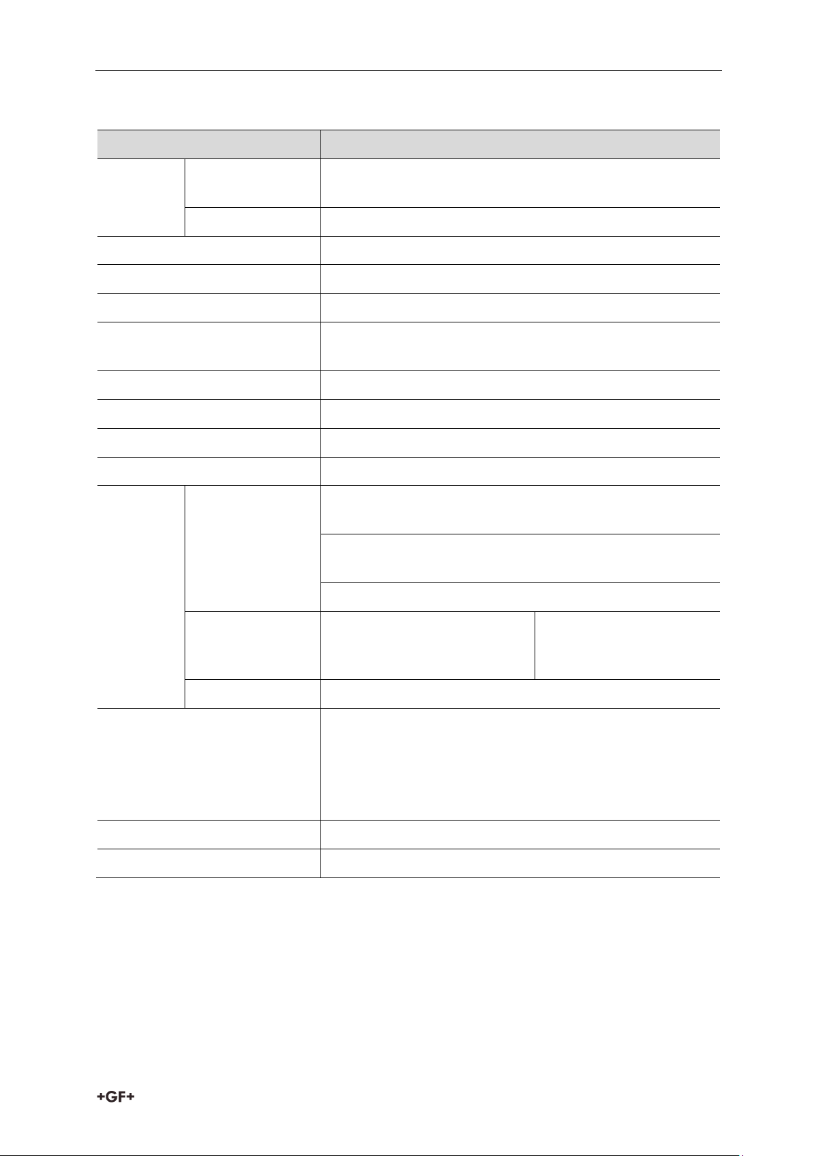
Instruction manual Technical data
Data
Kv value
Input data
Measured values
Between the reference point of the unit and reflection
plane (material surface), distance, level, and volume
Measuring range
Single cable 6 m (19,7 ft), single rod 2 m (6.6 ft)
Housing
Plastic BPT
Medium temperature
–30 °C ... +90 °C (–22 °F ... +194 °F
Minimal dielectric constant (r)
1.9
Medium pressure
- 0.1 … 1.6 MPa (- 1… 16 bar) max. allowed pressure
at 20 °C (68 °F)
Ambient temperature
With display: –20 °C … +60 °C (-4 °F… +140 °F)
Sealing
FPM
Ingress protection
IP 65 (NEMA 4 – 4X)
Power supply
18 … 35 V DC , nominal 24 V DC, Ex version 18 … 28V
Output
data
Output signals
Analogue: 4 … 20 mA, (3.9 … 20.5 mA) passive output,
error 22 mA
BUS: serial line, HART interface, terminal resistor max.
750 ohm
Display: LCD matrix
Accuracy
Liquids: 5mm. For probe
length L ≤10m 0.05% of the
range
Under ideal reflection
and stabilized
temperature conditions.
Resolution
3A
Electrical connection
2 x M20x1.5 metal cable glands Cable diameter: 7 … 13
mm (Ex), or M20x1.5 plastic cable glands, Cable
diameter: 6 … 12 mm
wire cross-section: 0.5 … 1.5 mm2 (shielded cable is
advised) + 2 x NPT ½” for cable gland
Electrical protection
Class III.
Mass (housing)
1.5 kg
6 Technical data
7
Page 8
Technical data Instruction manual
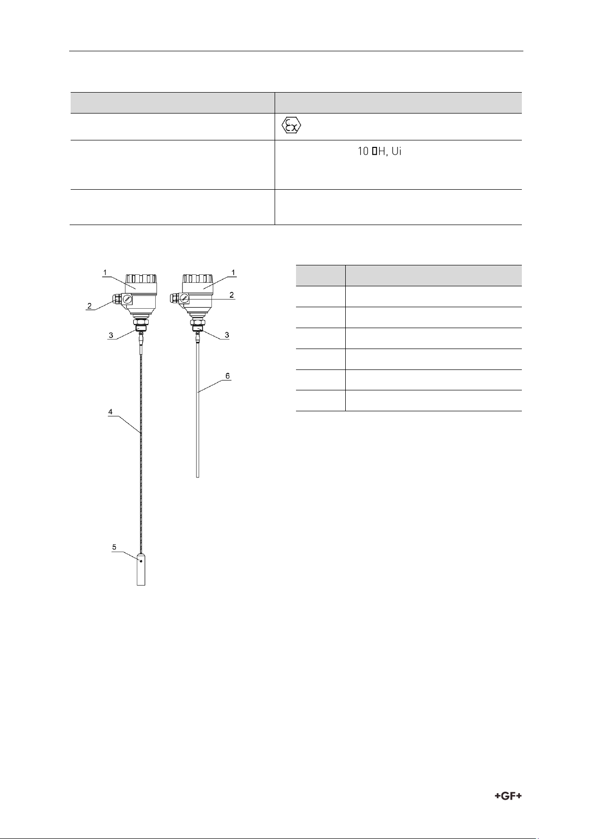
Type
Ex marking
II 1 D iaD A20/21 IP 65 T100°C
Intrinsically safe data
Ci ≤ 10 nF, Li ≤ ≤ 30 V, Ii ≤ 150 mA, Pi ≤
1 W For Ex transmitter only EEx ia power supply
should be used
Ex power supply
Uo < 30 V, Io < 150 mA, Po < 1 W, Supply range 18
V … 30 V
Nr.
Description
1
Housing
2
Cable gland
3
Process connection
4
Mono cable probe
5
Weight
6
Mono rod probe
Explosion Protection, Ex markings, Ex limit data
6.1 Dimensions
8
Page 9
Instruction manual Installation
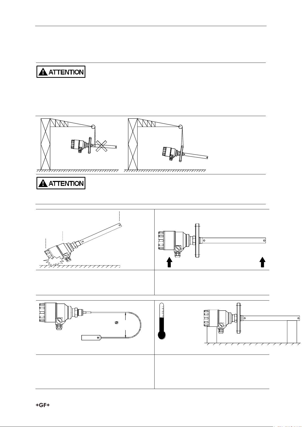
The device will weigh between approximately 1.5 kg or 3 lb, 12 kg or 25 lb.
Carry using both hands to lift the device carefully by the converter housing. If necessary, use
lifting gear. No attempt should be made to lift the instrument by its probe. Caution: The
probe is a critical gauge component. Do not damage - Handle with care!
Avoiding blows - avoid hard blows, jolts, impacts, etc. Caution: fragile electronics
Avoid bending (single rod and coaxial
probes) - Support the probe to avoid
bending.
400mm
minimum
+80°C
-40°C
Avoid cable kinks and fraying
Do not coil the cable less than 400 mm or 16 “
in diameter. Cable kinks or fraying will cause
measurement errors.
Storage temperature
7 Installation
7.1 Handling and Storage
9
Page 10
Installation Instruction manual
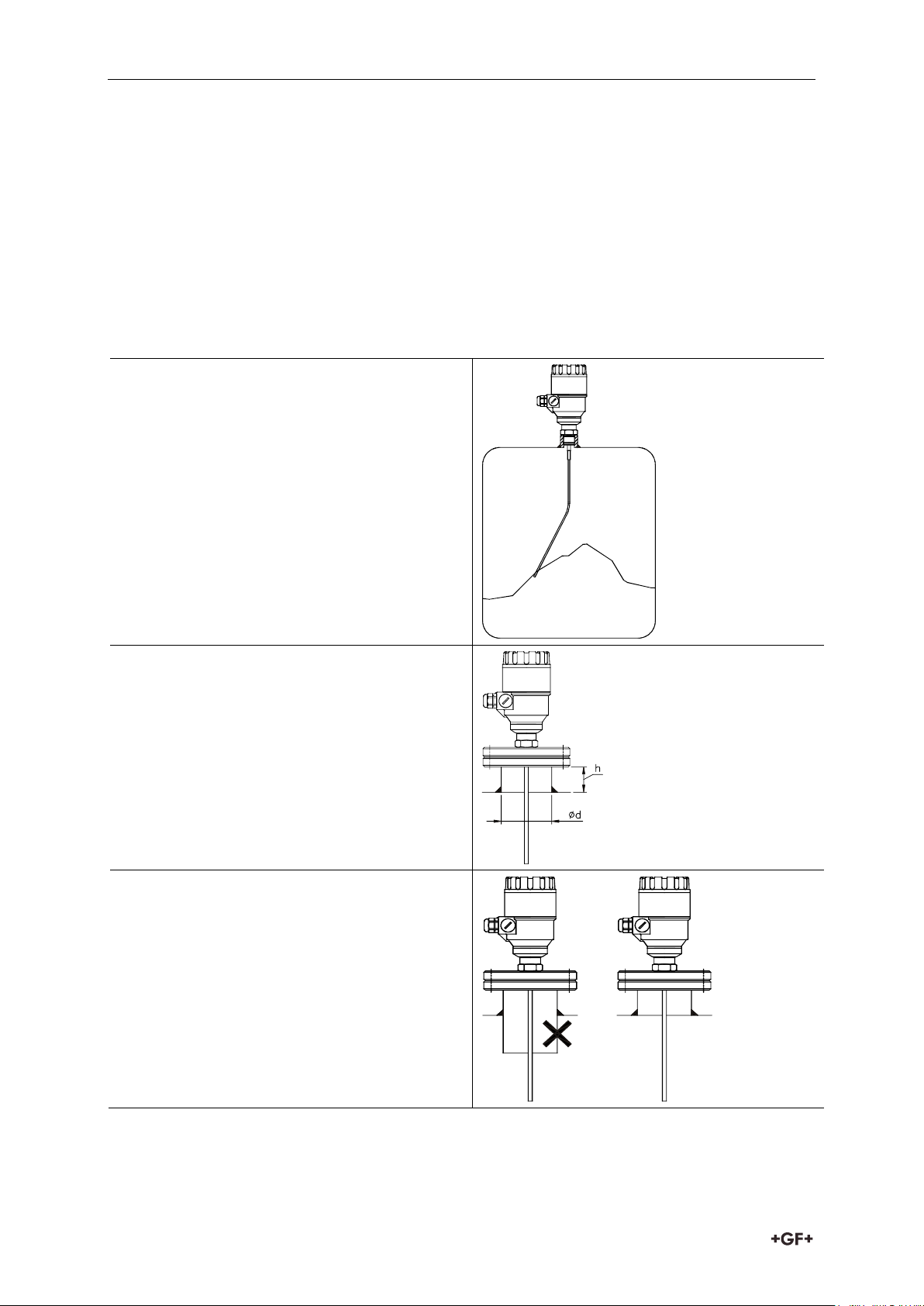
Threaded process connections
The simplest and most economical way is to
mount type 2291 directly on the tank with the
1” BSP or 1” NPT threaded connection.
Nozzle height
Do not fit a nozzle longer than its diameter,
especially for single probes and powder
applications.
h ≤ Ød
h = nozzle height and
d = nozzle diameter
Nozzles penetrating into tank
Caution: Do not use nozzles that penetrate
into the tank. This will disturb the emitted
pulse.
7.2 Mounting on the tank
7.2.1 Installation instructions: General notes
Prior the installation some consideration is to be made regarding tank fittings and tank shape.
Nozzle position in relation to the tank walls and other objects inside the tanks
(Warning: this free area will depend on the probe type selected: refer to later on in this
section) type of tank roof, i.e. floating, concrete, integral, etc; and base, i.e. conical, etc.
Whenever working on an installation, remember to: Disconnect the power supply before
starting work. However, the gauge may be installed when the tank contains product.
10
Page 11

Instruction manual Installation
Installation of two devices
If two devices are to be used on the same
tank, these should be mounted at a distance
of at least 2 m or 6.5 ft away from each other.
If not, interferences from the electromagnetic
(EM) fields generated by both instruments
may cause measurement errors.
Coaxial probes: the outer shell of the probe
contains the EM field: no minimum distance
required.
Process connection and entry pipe
Caution: Do not put the nozzle close to the
entry pipe.
Pouring the product directly onto the probe
will give false readings.
Install deflector plate if impossible to
distance gauge from entry pipe.
Install far from
entry pipe
or use a
deflector
plate
medium
Stilling wells
Tanks with floating roofs for petrochemical
applications: Use a stilling well.
1 Stilling well
2 Tank
3 Floating roof
4 Product (petroleum applications)
5 Well fixed to tank base (no roof deformation)
6 Sediment
11
Page 12

Installation Instruction manual
Probes: entanglement, straightness and tank
bottom clearance
Cable probes must be straight once inserted
into the tank.
They must also be far from other objects (e.g.
mixers) to avoid entanglement.
In order to maintain the gauge’s operating
characteristics, it is recommended to avoid
touching the tank bottom with the
counterweights (for cable probes) or probe
end (other types).
Avoid mounting near objects (discontinuities)
inside the tank that influence the probe’s EM
(electromagnetic) field
Install the gauge far from protruding objects
such as: heating tubes, sudden changes in
tank cross-section, tank wall reinforcements
and beams, weld lines and dip-stick pipes,
etc.
1. Agitator
2. Support beam perpendicular to the pulse
direction
3. Abrupt changes in tank cross section
4. Heating tubes
5. Alternative solution: reference chamber
- electromagnetic field is within chamber
6. Gauge electromagnetic field:
Any intruding metallic object will be
detected in this zone if perpendicular to
the emitted pulse direction.
Do not fit the gauge near to these objects.
When measuring liquids the use of a stilling
well or reference chamber is favorable
because it ensures electromagnetic
protection for an accurate measuring.
Use a sunshade if the unit is exposed to
direct sunlight.
No electromagnetic field outside the
reference chamber.
12
Page 13

Instruction manual Installation
Fastening the probe to the tank bottom
Flexible probes can be fastened with a chuck (ring), turnbuckle or similar fastening device to
the tank bottom.
Shortening cable probes
If required, the cable probe can be shortened, but this applies only when used in liquids.
Procedure
1. Detach socket set screw M6x10 (ISO 4026)
with 5 mm Allen (hexagon) key (ISO 2936).
2. Pull cable out of counterweight and
shorten to required length using cable
cutters to prevent the cable wires and
strands from splaying out.
3. Insert cable back into counterweight and
tighten down screws
4. Change configuration parameters to new
probe length; the reference point is the
top edge of the weight.
False readings
1. Do not let the probe touch the side of the
nozzle.
7.2.2 Specific installation instructions: Gauge – solid applications
13
Page 14

Installation Instruction manual
Conical silo nozzles, false readings and
traction on the cable probes
2. High traction forces:
We recommend that the probe should not
be anchored to avoid excessive traction
loads on the cable.
3. Bending and traction:
Position the connection on the roof at ½
radiuses of the tank and with minimum
nozzle height. This will avoid damage due
to bending and traction during emptying.
Product build-up can occur under the nozzle:
this may weaken the pulse.
Avoid cavities that permit the build-up of
deposits.
No.
Description
1
Detach the cover of the unit
2
Guide the cable into the housing
through the cable gland
3
Remove a 4 mm length of isolation
from the wires and cut away the free
part of the shielding
4
Connect the wires of the current loop
to terminals 2 and 3 (any polarity).
5
Pull back the cable till a 10 mm cable
length remains in the housing behind
the cable gland.
Tighten the cable gland using two
spanners.
Check the connection of wires and the
tightness at the cable gland
6
Array the wires in the housing and
screw the cover on the housing.
The 500V AC insulation test should not
be performed on the instrument
because of the overvoltage protection
of the electronics.
7.3 Wiring
Wiring in non-Ex environment Wiring in non-Ex environment
14
Page 15

Instruction manual Installation
Electrostatic discharge (E.S.D.)
Type 2291 non-Ex and Ex gauge electronics
are shielded up to 4 kV against E.S.D.
Note: E.S.D. cannot be solved by Type 2291
E.S.D. protection.
It is the customer’s responsibility to avoid
E.S.D. by grounding the tank, product and
probe installation.
1. Danger of injury
The probe may receive an electrostatic
discharge during operation; earth the
probe by pushing it against tank wall with
a suitably isolated tool just before
touching it to avoid receiving a shock.
2. Earth the entry pipe and product.
Connection to the EP network (grounding).
Screw type terminal (EP) on the housing max. cable cross-section: 4 mm².
The housing of the Type 2291 must be grounded.
Grounding resistance R < 1 Ohm
The shielding of the signal cable should be grounded at the control room.
Avoid coupling of electromagnetic noises place the singnal cable away from power-current
cables.
15
Page 16

Installation Instruction manual
=
U
S
R
A
HART
4 ... 20mA
U
E
MikroTREK 2-wire
mA
L
Power supply
Nominal voltage
24 V DC
Maximum voltage (U
input
):
35 V DC
Minimum voltage (U
input
):
dependent on load impedance, see graph
below
Load impedance RA
Loop resistance, R
loop
R
HART
+ R
cable
+ R
ammeter
Ohm
Minimum load impedance RA
0 Ohm
Maximum load impedance RA
750 Ohm
RHART resistance for HART® communication
250 Ohm, recommended
2291 2-wire
Non-hazardous-duty version
Line A = minimum voltage at the Type 2291 wire terminals
Line B = minimum supply voltage (for voltage drop caused by a 250 Ohm loop resistance)
Example for calculating the power supply: The voltage drop is tested at 22 mA:
U
power minimum 22
U
power minimum 22
16
= 22 mA x load impedance + U
= 22 mA x 250 Ohm + 10 V = 5.5 V + 10 V = 15.5 V
input minimum 22
Page 17

Instruction manual Installation
An ’Ex’ repeater power supply unit must be
used
For calculation of the supply voltage the same
applies as for the standard non-’Ex’ version.
The connected Ex repeater must be HART®-
compatible so that it can be operated with the
GF Signet Eview 2 communication software.
The HART adapter should be connected to the
intrinsically safe input of the Ex repeater!
The units with plastic coating can only be
used in IIB gas class hazardous area.
R
A
=
non area Ex
Ex area
HA RT
Mi roTREK 2c -wire
mA
L
[Ex ia]
4-20mA
EEx ia
2291 2-wire
In order to cover the whole current range, the voltage drop must also be tested at 4 mA:
By analogy, the following applies:
U
power minimum 4
U
power minimum 4
= 4 mA x load impedance + U
input minimum 4
= 4 mA x 250 Ohm + 18 V = 1 V + 18 V = 19 V
At a load impedance of 250 Ohm a power supply voltage of 19 V is sufficient to energize the
current device range of 4 to 20 mA.
Hazardous-duty version
Connect the wires of the current loop to terminals 2 and 3 (any polarity).
The intrinsically safe certified device may only be used in conjunction with an other
intrinsically safe certified equipment.
All the allowed electrical safety data indicated on the nameplate must be observed.
7.4 Power on and start-up
The Type 2291 wire is pre-configured in accordance to customer order specifications and
measurements can be made immediately. A start-up time of less than 60 seconds should be
allowed once the unit is connected and the power is switched on.
If the probe length has been shortened since delivery, please refer to section.
17
Page 18

Programming type 2291 Instruction manual
E
The display based on LCD technology, do not expose to continuous
direct sunlight to avoid display damage.
If type 2291 is not equipped with a sunshade and ambient
temperature exceeds the operating temperature of LCD do not leave
the LCD in the instrument!
Display
64x128 Dot-matrix LCD, glyphs, units and bargraph
Ambient temperature
– 20°C…+60°C
Housing material
PBT fiberglass, plastic (DuPont)
E
8 Programming type 2291
The main parameters of the Type 2291 can be also set using the display unit.
The default display shows the primary measured value (which the output current is calculated
from).Besides the numerical display there is a bargraph on the right showing the value of the
current output.
Programming is helped by a text-based menu. Navigation in the menu can be done with
/
/ / buttons.
8.1 The display unit
The display unit is a 64x128 dot-matrix LCD display which can be plugged into the transmitter.
8.1.1 Behavior in manuals programming mode
After power-up Type 2291 shows the measured value on the LCD.
Remote mode:
If the instrument senses external HART communication it changes its display mode and
shows a "REMOTE MODE" message in the bottom of the display. In this mode the measured
values are refreshed according to the queries of the external HART master.
If the HART master does not refresh the display will show the last measured values.
In the absence of display unit the COM LED indicates the HART communication.
If HART communication stops the COM LED turns off after 120 sec.
Entering the menu can be done by pressing the
pressing and buttons.
Enter into selected menu point with E button. Exit to the previous menu with
The buttons work only in presence of display unit.
When leaving the Type 2291 in (programming) menu after 30 minutes the instrument
automatically returns to measuring mode.
button. Scrolling the menu can be done by
button.
If display unit is removed the instrument instantly returns to measuring mode.
18
Page 19

Instruction manual Programming type 2291
Main menu
BASIC SETUP
OUTPUT SETUP
APPLICATION
Sub-menu
TANK HEIGHT
CURRENT MODE
APPLICATION TYPE
DEAD ZONE
FAILURE CURRENT
CLOSE-END BLOCKING
CURRENT MIN
DAMPING TIME
CURRENT MAX
PROBE LENGTH
ERROR DELAY
E
E
Because manual programming (with display unit) and remote programming (with external
HART master, or GF Signet Eview 2 software) cannot be performed at the same time (as both
of them act like a HART master) only one programming mode has priority and this is manual
programming.
During manual programming the instrument sends the "BUSY" response to the external
HART master device. (HART response code 32 - Device is busy)
8.1.2 Manual programming
Manu structure
Changing parameters can be done by selecting a sub-menu and pressing E button in two
ways:
Text-based list:
Navigation is the same as in menu lists.
Accept changes with
button, cancel changes (and exit) with button.
Numerical field:
Serves for editing a numeric value.
Editing is helped by a cursor (inverted character).
Change the value of the selected digit with
/
buttons
(There is no under-, and overflow between the characters).
Selecting a digit can be done using the
Accept changes with
button.
button.
After accepting the parameter change the Type 2291 checks the parameter and
downloads it.
If parameter is incorrect the CHECK/WRITE FAILED! message appears.
19
Page 20

Programming type 2291 Instruction manual
Nr.
Description
A
Tank height
B
Probe length
C
Detection delay
D
Non-measurable zone
E
Minimum distance between
non-measurable zone and
dead zone
F
Upper dead zone
G
Measuring range
H
Reference point at tank
bottom
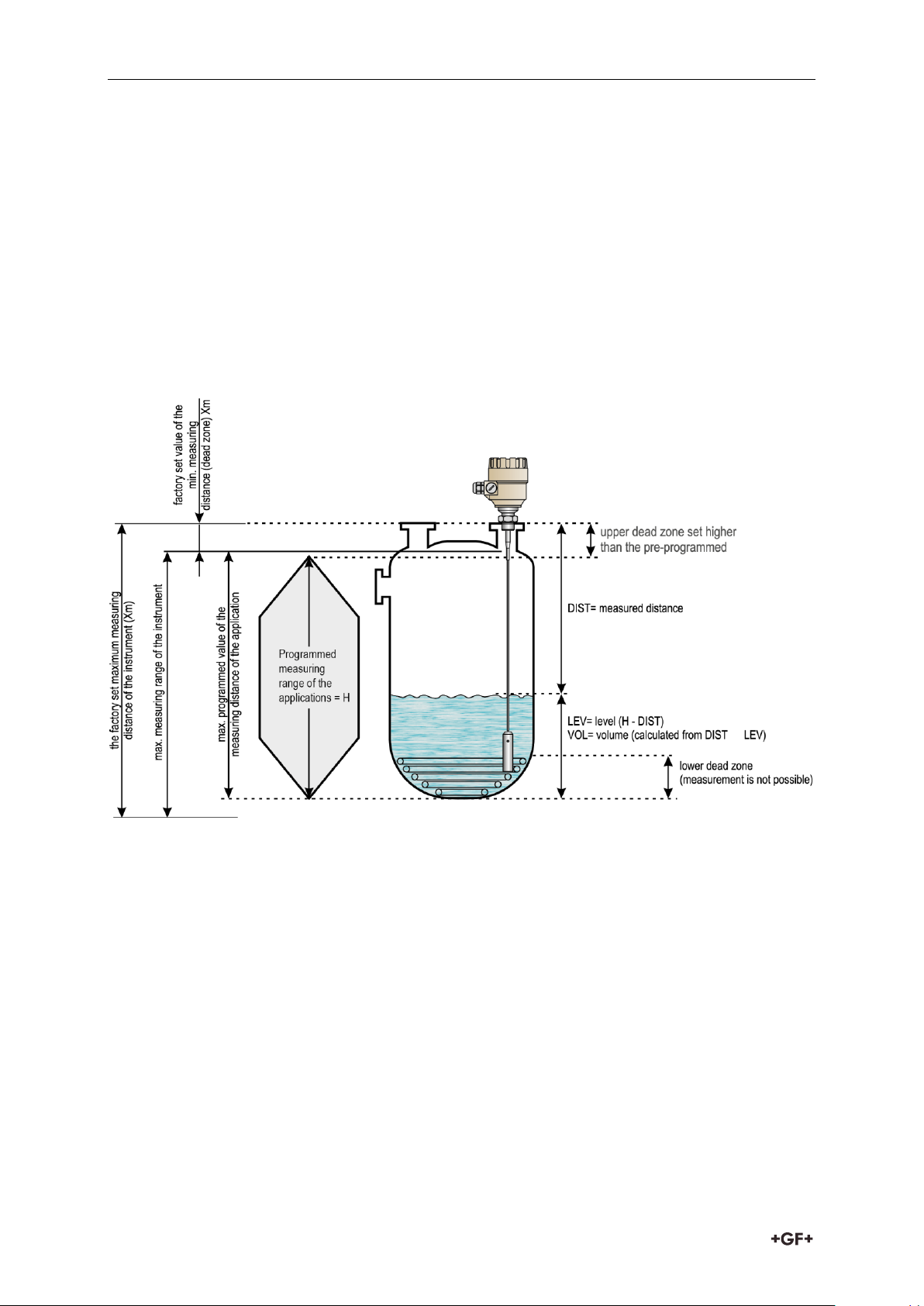
8.2 Characteristics
This subsection explains:
the four principle configurations for setting up a measurement scale and what the user
should be aware of in each case;
what happens when the tank is full or empty;
what is the level threshold and how to modify it
what happens when level is measured when more than one product in the tank;
The measurement scale:
Five possible configurations for analogue current output – with “Level” selected in the EView
2 configuration software.
The configurations described below are illustrated in the above diagram
1. The “current output” range is smaller than the max. possible measuring range
2. The “current output” range is equal to the measuring range:
Scale min.: 4 mA = tank height – probe length + H
Scale max.: 20 mA = tank height – dead zone
3. The “current output” range is greater than the measuring range:
Scale min.: 4 mA = 0.0
Scale max.: 20 mA = tank height – dead zone
4. The “current output” range is greater than the measuring range:
Scale min.: 4 mA = tank height – probe length + H
Scale max.: 20 mA = tank height
20
Page 21

Instruction manual Programming type 2291
Zone 1 : Dead and detection delay zones
Marker “Tank full” and “Level lost” is displayed when
the product enters the dead zone and no reflection is
found.
This will also occur once the level reflection is within the
detection delay zone.
The gauge assumes the tank is full and displays the
maximum level value.
The gauge searches for a reflection along the entire
length of the probe.
Zone 2 : Full zone (and dead zone)
Marker “Tank full” is displayed in this zone.
If the gauge loses the signal in this zone, it reacts as in
zone 1: the tank is assumed to be full.
The gauge searches for a reflection along the length of
the probe.
Zone 3 : Central measurement zone
The gauge searches along the length of the probe for the
largest pulse reflection.
If the pulse is lost the reading freezes at the last value.
Marker “Level lost” will be displayed.
Zone 4 : Empty zone
If the reflection is lost here then the gauge assumes the
tank is empty and marker “tank empty” is displayed.
The gauge searches for a reflection in this zone but
makes a search along the entire length of the probe once
every minute.
The reading will remain frozen during this time.
The short circuit reflection will become larger than
product reflection at this time.
5. The “current output” range is greater than the measuring range:
Scale min.: 4 mA = 0.0
Scale max.: 20 mA = tank height
NOTE: The reference point for distance measurements is the bottom of the flange face.
8.2.1 Gauge operating logic when the reflection is lost
The product reflection pulse is usually lost when the level is in the top dead zone or near the
bottom of the tank. The diagram below shows the action taken by the gauge depending on
where the last reflection was lost.
21
Page 22

Programming type 2291 Instruction manual
8.2.2 Gain and voltage amplitude
As explained in the measuring principle in the introduction, the level of a product is converted
from a return signal (the product reflection) received by the gauge: this signal has taken a
certain amount of time to return to the gauge and it has a certain strength / size measured
in milli-volts (dependant on the dielectric constant r of the product).
All pulse signals returning to the gauge electronics block (including flange, obstruction and
the product surface reflections) are converted to voltage amplitudes. The gauge’s
microprocessor looks for part of the largest signal that is over a set voltage amplitude, called
the “threshold”, and identifies this as the product being measured. For this signal to be
usable by the gauge, the microprocessor will amplify the signal by increasing the gain. Once
the signal is within a set “working” range, the gauge follows this signal. The gauge registers
any changes in time for this part of the signal to return to the converter and translate this into
a displayed level or volume.
Gain is a function of voltage amplitude.
This defines the default threshold value when the gauge is searching for the product level. A
strong return signal will be given a low gain (i.e. Gain 0 or a small amplification). However, if
the signal is very weak, then a Gain of 3 (i.e. high signal amplification) is given.
Example of signal amplification:
The level signal can be optimized by way of two factors:
22
Page 23

Instruction manual Programming type 2291
Gain
0 1 2 3 Amplification factor
1.05
2.10
4.37
8.93
Nr.
Description
1
Initial pulse
2
Flange reflection
3
Level signal
4
Interference signal
Nr.
Description
1
Initial pulse
2
Flange reflection
3
Level signal
4
Interference signal
5
Threshold
Amplification factor
The amplitude of the signals is proportional to the dielectric constant r of the product. At low
amplitudes the signal should be amplified.
The amplification factor is dependent on the dielectric constant r and on the probe type. The
device sets the gain automatically.
The following factors apply to the set gain:
Level threshold
The level threshold suppresses interference signals so that only the reflections from the
product surface (level signal) are shown. The factory setting of the level threshold is suitable
for standard applications.
The threshold will need to be adjusted in the case of very low dielectric constants r, multiple
interference reflections or unfavourable installation conditions.
The illustrations below show interference signals when the oscilloscope function is used.
These reflections can be due to various causes, e.g. tank internals or multiple reflections
within the measuring range.
Even though the interference signals are very weak, the threshold should nevertheless be set
to a value above these signals.
23
Page 24

Programming type 2291 Instruction manual
In the diagram above it can be seen that the level of the threshold is not constant:
400 mV at 1000 mm or 3.3 ft, and only 250 mV at 10000 mm or 33 ft. No attenuation is required
at a probe length ≤ 3000 mm or 10 ft. The form of the threshold is dependent on attenuation
and is automatically adjusted by the device over the measured length.
Setting the level threshold
If the level threshold is set too high, i.e. it is greater than the amplitude of the level reflection,
the device will not find any level even with maximum amplification.
If the level threshold is set too low, i.e. it is below the amplitude of some of the interference
signals, the device will identify and indicate one of these interference signals as a level
reflection only if the tank is empty.
Precise setting of the level threshold is especially important when the dielectric constant r is
low.
To set, the level (amplitude of the reflection) must be known. A level of 500 mm or 20” is ideal.
The level threshold should be half-way between the invalid interference signals and the level
reflection signal.
The reflection from the probe tip, which is clearly identifiable at a low r value, does not need
to lie below the level threshold.
8.2.3 Typical signal trends
The following diagrams show characteristic signals that have been recorded with the
oscilloscope function.
Rod or cable probe with gain 1 Rod or cable probe with gain 2
The signal from coaxial probes does not include the flange reflection, due to the mechanical
setup which does not produce any change in impedance at the flange.
The amplitude of reflection from the product surface increases as the level rises and
decreases as the level falls
24
Page 25

Instruction manual Programming type 2291
Nr.
Description
1
is located between a distance of
2000 and 4000 mm or 6.5 and 13
feet.
2
is the level threshold. This is shown
below:
Nr.
Description
1
is located over 4000 mm or 13 feet.
2
threshold
3
interference signals
8.2.4 Automatic adjustment
To maintain a sufficiently strong reflection signal, the gain is adjusted automatically.
When the amplitude of the level reflection decreases, the gain will increase to compensate for
the loss in signal amplitude. Gain and level threshold thus maintain the same proportion.
At gain 3, the level signal
The amplification factor is 3
The level has dropped, increasing the distance between level and flange.
The interference signals are now below the level threshold (2), whose lower limit is 50 mV.
As in the diagram above, the amplification factor is 3.
In both cases, the automatically adjusted gain of the threshold indicates all signals located
above one-half of the amplitude of the level signal.
In the event of operational or installation faults, you can frequently identify the cause of the
fault by means of this function and normally eliminate it yourself.
8.2.5 Level measurement when more than one phase or layer in the tank
Level can be measured with more than one phase in the tank.
This requires setting a parameter in the factory menu (Fct. 1.1.3: Application Type) to the
following measurement mode:
2 liquids, 1 level: For measuring level with two or more phases
1 liquid, 1 level: For measuring one phase or liquid
25
Page 26

Programming type 2291 Instruction manual
Nr.
Description
1
Level measurement signal
2
Threshold
Application Type set to 1 liquid, 1 level, the wire will
search for the return signal with the highest
amplitude (i.e. higher than the threshold). It will
measure the oil level.
Nr.
Description
1
Threshold
2
Level signal
3
Oil-water interface signal
Application Type set to 2 liquids, 1 level, the wire
will search for the first return signal higher than
the control threshold. It will correctly measure the
oil level (i.e. “level”).
Characteristics
The level of the top product can be detected
if it has a minimum layer of approximately 100 mm - when measuring a top product with a
dielectric constant of r =2.4.
The mode “2 liquids, 1 level” permits level to be measured even when more than 2 liquids are
present in the tank. The first return signal is identified as being level and the second is
ignored.
This mode may be used with all probe types
Example application 1:
Level measurement of oil (1 liquid in the tank)
Example application 2:
Level measurement when there are 2 liquids (oil/water) in the tank – using a correctly
configured gauge
26
Page 27

Instruction manual Troubleshooting
Event
Fault
Action
Error messages
“Tank full” status
marker on*, reading
frozen at max. or min.
value
No fault. The level has reached
(and possibly risen above) the top
configured measurement limit
and is either displaying the
maximum (when measuring level)
or minimum (when measuring
distance) output.
None.
Measurements should be
normal once the level is in the
configured measurement
range.
“Tank empty” status
marker on*, reading
frozen at max. or min.
value
No fault. The level has entered the
gauge’s bottom dead zone and
can no longer detect a return
signal. Either the maximum (when
measuring distance) or minimum
(when measuring level) output is
displayed.
None.
Measurements should be
normal once the level is in the
configured measurement
range.
“Tank full” and “Level
lost” status marker
on*, reading frozen at
max. or min. value
No fault. The level has entered the
gauge’s top dead zone and can no
longer detect a return signal.
Empty the tank below the top
measurement range limit and
check the measurement.
“Level lost” status
marker on*, reading is
frozen
The instrument has lost the level
signal, has searched but not yet
found the return pulse. This may
occur if the pulse has dropped
below the threshold. Parasite
signals from the flange or
obstructions in the tank may
render the gauge unable to
identify the correct signal.
Ensure that tank is emptied
below maximum level and
check the measurement.
“Reference not found”
status marker on*
Occurs when there is a problem
with the time base on the HF
board.
Please contact GF Piping
Systems.
“Level lost” and
“Reference not found”
status markers on*,
reading frozen
The probe has received an
electrostatic discharge.
The gauge will search for the
level again and resume
readings. If the reading
remains frozen then the signal
converter may have been
damaged by ESD and may need
replacing.
Please contact GF Piping
Systems
“Flange not found”
status marker on*
The signal converter has been
incorrectly configured to measure
with a cable or rod probe when it
is equipped with a coaxial probe.
Contact GF Piping Systems for
the corrective procedure.
9 Troubleshooting
27
Page 28

Troubleshooting Instruction manual
Event
Fault
Action
Error messages
This may be also due to
installation on a long nozzle which
has the effect of attenuating the
flange pulse.
“Delay out of limits”
status marker on*,
reading is frozen.
The emitted pulse has not been
detected.
The gauge will not work until it
has been found
Contact GF Piping Systems for
the corrective procedure.
“Delay out of limits”
status marker on*,
reading is frozen.
The emitted pulse has not been
detected.
The gauge will not work until it
has been found.
The signal converter may need
replacing. Please contact GF
Piping Systems.
“Negative voltage
error”*
Occurs when there is a problem
with the time base on the HF
board.
Please contact GF Piping
Systems.
“VC01 voltage error” *
“VC02 voltage error” *
“Reprogramming
FPGA” *
Event
Fault
Action
General operation
Instrument is not
accurate with a
product that has a
high dielectric
constant. A constant
offset is observed
when taking
measurements.
Tank height is not correct.
Check current output and tank
height parameters.
If the signal converter has been
replaced, verify that factory
calibration parameters are still
the same.
Ask GF Piping Systems for the
factory calibration sheet (if not
supplied) and the password for
access to the factory menu.
The Type 2291 2-wire
indicates an incorrect
level value.
The Type 2291 2-wire measures a
non-valid reflection.
Check the tank for
obstructions and verify that the
probe is clean.
In the case the indicated level
is close to the nozzle, increase
the detection delay and the
dead zone with the same ratio
or increase the threshold level
if the full measurement range
is essential.
The threshold level must be
adjusted so that it masks the
* Gauge connected to GF Signet EView2 software.
28
Page 29

Instruction manual Troubleshooting
Event
Fault
Action
General operation
disturbances. It also gives
enough margin for detection of
the level pulse.
Very large pulses along the
measurement signal
(same amplitude as the initial
pulse) can be caused by a
probe which is touching the
nozzle or the tank side (see
section 1.3.5). Ensure that no
contact is possible.
Instrument is not
accurate when there
are two or more
phases in the tank.
The instrument may be incorrectly
configured for this type of
application i.e. it is measuring the
interface instead of the level.
Contact GF Piping Systems for
the corrective procedure or
refer to the Service Manual.
Check if application type had
been set to: Application Type is
set to “2 liquids, 1 level”.
Check also that there is a layer
of more than 100 mm of top
product above the bottom
product.
Event
Fault
Action
Electrical Connections and Communication Output
Current Output value <
4 mA.
No power supply
Check the power supply
Connection of the device is
incorrect.
Check the connection between
the device and the power supply.
The calibration of the current
output is incorrect.
Execute the calibration if you have
authorized access or contact GF
Piping Systems Service centre.
Reads 22 mA.
An error has occurred.
This happens in case the range 420 mA / error 22 mA is selected.
Check the status of the device by
selecting the marker window (F8)
or enter the status (4.0) menu of
the HART® communicator.
The device is in its start-up
phase
Wait 50 seconds.
If the current value drops to a
value between
4 and 20 mA, and goes
immediately back to 22 mA,
contact your GF Piping Systems
Service Centre.
29
Page 30

Repair and Maintenance Instruction manual
Remote program 90
Basic setup
Output setup
Application
Service
Application 97
Treshold
Service 89
Service code
Application type
Epsilon R
Treshold 98
Ampl= 00345 mV
Dist.= 1.25 m
Pulse ampl.= 820mV
Gain= 3
Output setup 92
Current mode
Current min.
Current max.
Failure current
Error current
Length unit 120
m
cm
mm
ft
inch
Error delay 95
None
10 sec
20 sec
30 sec
1 min
2 min
5 min
15 min
Current mode 93
Level
Distance
Volume
Ullage volume
Failure current 94
Hold
22 mA
Application type 94
1 Liq. 1 Level
2 Liq. 1 Level
Basic setup 91
Length unit
Tank height
Dead zone
Close-end blocking
Damping time
Probe length
A product marked with this symbol must be taken to a separate collection point for
electrical and electronic devices. If you have any questions regarding disposal of
the product, please contact your national agent for GF Piping Systems.
10 Repair and Maintenance
Type 2291 does not require maintenance on a regular basis. In some very rare instances,
however, the probe may need a cleaning from deposited material. This must be carried out
gently, without damaging the probe. Repairs during or after the warranty period are carried
out exclusively at the Manufacturers. The equipment sent back for repairs should be cleaned
or neutralized (disinfected) by the User.
11 Accessories
The level transmitter must be operated in intrinsically safe circuit only.
The metal enclosure of the unit must be connected to the EP circuit.
12 Set-up parameters
Parameters in the Service Menu are read-only parameters. Changing of these parameters
require the service code of the instrument.
13 Disposal
Before disposing of the different materials, separate them into recyclable materials,
normal waste and special waste.
Comply with local legal regulations and provisions when recycling or disposing of the
product, individual components and packaging.
Comply with national regulations, standards and directives.
30
Page 31

31
Page 32

GF Piping Systems
Worldwide at home
Our sales companies and representatives
ensure local customer support in over 100 countries
www.gfps.com
Argentina / Southern South America
Georg Fischer Central Plastics
Sudamérica S.R.L.
Buenos Aires, Argentina
Phone +54 11 4512 02 90
gfcentral.ps.ar@georgfischer.com
www.gfps.com/ar
Australia
George Fischer Pty Ltd
Riverwood NSW 2210 Australia
Phone +61 (0) 2 9502 8000
australia.ps@georgfischer.com
www.gfps.com/au
Austria
Georg Fischer
Rohrleitungssysteme GmbH
3130 Herzogenburg
Phone +43 (0) 2782 856 43-0
austria.ps@georgfischer.com
www.gfps.com/at
Belgium / Luxembourg
Georg Fischer NV/SA
1070 Bruxelles/Brüssel
Phone +32 (0) 2 556 40 20
be.ps@georgfischer.com
www.gfps.com/be
Brazil
Georg Fischer Sist. de Tub. Ltda.
04571-020 São Paulo/SP
Phone +55 (0)11 5525 1311
br.ps@georgfischer.com
www.gfps.com/br
Canada
Georg Fischer Piping Systems Ltd
Mississauga, ON L5T 2B2
Phone +1 (905) 670 8005
Fax +1 (905) 670 8513
ca.ps@georgfischer.com
www.gfps.com/ca
China
Georg Fischer Piping Systems Ltd
Shanghai 201319
Phone +86 21 3899 3899
china.ps@georgfischer.com
www.gfps.com/cn
Denmark / Iceland
Georg Fischer A/S
2630 Taastrup
Phone +45 (0) 70 22 19 75
info.dk.ps@georgfischer.com
www.gfps.com/dk
Finland
Georg Fischer AB
01510 VANTAA
Phone +358 (0) 9 586 58 25
Fax +358 (0) 9 586 58 29
info.fi.ps@georgfischer.com
www.gfps.com/fi
France
Georg Fischer SAS
95932 Roissy Charles de Gaulle Cedex
Phone +33 (0) 1 41 84 68 84
fr.ps@georgfischer.com
www.gfps.com/fr
Germany
Georg Fischer GmbH
73095 Albershausen
Phone +49 (0) 7161 302-0
info.de.ps@georgfischer.com
www.gfps.com/de
India
Georg Fischer Piping Systems Ltd
400 083 Mumbai
Phone +91 224007 2001
branchoce@georgfischer.com
www.gfps.com/in
Indonesia
George Fischer Pte Ltd –
Representative Oce
Phone +62 21 2900 8564
Fax +62 21 2900 8566
sgp.ps@georgfischer.com
www.gfps.com/sg
Italy
Georg Fischer S.p.A.
20063 Cernusco S/N (MI)
Phone +39 02 921 861
it.ps@georgfischer.com
www.gfps.com/it
Japan
Georg Fischer Ltd
556-0011 Osaka,
Phone +81 (0) 6 6635 2691
jp.ps@georgfischer.com
www.gfps.com/jp
Korea
GF Piping Systems
Georg Fischer Korea Co., Ltd.
Unit 2501, U-Tower
120 HeungdeokJungang-ro (Yeongdeok-dong)
Giheung-gu, Yongin-si, Gyeonggi-do, Korea
Phone: +82 31 8017 1450
Fax : +82 31 217 1454
kor.ps@georgfischer.com
www.gfps.com/kr
Malaysia
George Fischer (M) Sdn. Bhd.
40460 Shah Alam, Selangor Darul Ehsan
Phone +60 (0) 3 5122 5585
Fax +603 5122 5575
my.ps@georgfischer.com
www.gfps.com/my
Mexico / Northern Latin America
Georg Fischer S.A. de C.V.
Apodaca, Nuevo Leon
CP66636 Mexico
Phone +52 (81) 1340 8586
Fax +52 (81) 1522 8906
mx.ps@georgfischer.com
www.gfps.com/mx
Middle East
Georg Fischer
Piping Systems (Switzerland) Ltd
Dubai, United Arab Emirates
Phone +971 4 289 49 60
gcc.ps@georgfischer.com
www.gfps.com/int
Netherlands
Georg Fischer N.V.
8161 PA Epe
Phone +31 (0) 578 678 222
nl.ps@georgfischer.com
www.gfps.com/nl
Norway
Georg Fischer AS
1351 Rud
Phone +47 67 18 29 00
no.ps@georgfischer.com
www.gfps.com/no
Philippines
George Fischer Pte Ltd
Representative Oce
Phone +632 571 2365
Fax +632 571 2368
sgp.ps@georgfischer.com
www.gfps.com/sg
Poland
Georg Fischer Sp. z o.o.
05-090 Sekocin Nowy
Phone +48 (0) 22 31 31 0 50
poland.ps@georgfischer.com
www.gfps.com/pl
Romania
Georg Fischer
Piping Systems (Switzerland) Ltd
020257 Bucharest - Sector 2
Phone +40 (0) 21 230 53 80
ro.ps@georgfischer.com
www.gfps.com/int
Russia
Georg Fischer
Piping Systems (Switzerland) Ltd
Moscow 125040
Phone +7 495 748 11 44
ru.ps@georgfischer.com
www.gfps.com/ru
Singapore
George Fischer Pte Ltd
11 Tampines Street 92, #04-01/07
528 872 Singapore
Phone +65 6747 0611
Fax +65 6747 0577
sgp.ps@georgfischer.com
www.gfps.com/sg
Spain / Portugal
Georg Fischer S.A.
28046 Madrid
Phone +34 (0) 91 781 98 90
es.ps@georgfischer.com
www.gfps.com/es
Sweden
Georg Fischer AB
117 43 Stockholm
Phone +46 (0) 8 506 775 00
info.se.ps@georgfischer.com
www.gfps.com/se
Switzerland
Georg Fischer
Rohrleitungssysteme (Schweiz) AG
8201 Schahausen
Phone +41 (0) 52 631 30 26
ch.ps@georgfischer.com
www.gfps.com/ch
Taiwan
Georg Fischer Co., Ltd
San Chung Dist., New Taipei City
Phone +886 2 8512 2822
Fax +886 2 8512 2823
www.gfps.com/tw
United Kingdom / Ireland
George Fischer Sales Limited
Coventry, CV2 2ST
Phone +44 (0) 2476 535 535
uk.ps@georgfischer.com
www.gfps.com/uk
USA / Caribbean
Georg Fischer LLC
9271 Jeronimo Road
92618 Irvine, CA
Phone +1 714 731 88 00
Fax +1 714 731 62 01
us.ps@georgfischer.com
www.gfps.com/us
International
Georg Fischer
Piping Systems (Switzerland) Ltd
8201 Schahausen/Switzerland
Phone +41 (0) 52 631 30 03
Fax +41 (0) 52 631 28 93
info.export@georgfischer.com
www.gfps.com/int
The technical data are not binding. They neither constitute expressly
warranted characteristics nor guaranteed properties nor a guaranteed durability.
They are subject to modification. Our General Terms of Sale apply.
GFDO_6447_4 (07.16)
© Georg Fischer Piping Systems Ltd
CH-8201 Schaffhausen/Switzerland, 2016
 Loading...