

Page 1
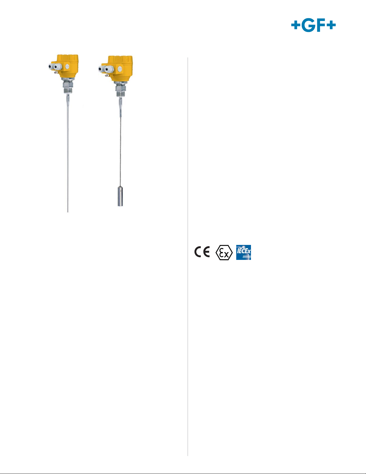
2291 Guided Wave Radar Level Transmitter
Features
• Measuring range up to 6 m (19.6 ft)
• Accuracy: ± 5 mm (0.2 in)
• PP / PFA coated probes available on request
• Rod & cable versions available
• Minimum εr 1.9
• 2-wire version
• Graphic LCD display
• 4 to 20 mA + HART output
• Medium temperature range: -30 °C to +90°C
(-22 °F to +194 °F)
The 2291 Guided Wave Radar level transmitter is
designed for continuous level measuring of conductive
or non-conductive liquids, pulps and solids. The 2291
level gauge operates based on the well-known TDR
(Time Domain Reflectometry) principle. Micropulses are
sent along a probe guide at the speed of light. As soon
as the impulse reaches the surface of the medium, it is
reflected back to the electronic module. Level distance
is directly proportional to the flight time of the impulse.
The reflected signal is dependent on the dielectric
constant of the material; the feasibility of the
measurement is ε
unaffected by the properties of the medium as well
as that of the space above it. Measurement is also
unaffected by the change in the physical properties of
the materials such as temperature, pressure, dielectric
constant.
≥ 1.9. The TDR technology is
r
• Maximum process pressure: 40 bar (580 psi)
• IP67 protection
Applications
• Inventory Tanks
• Day Tanks
• Process Vessels for Mixing & Batching
• Bypass Applications (requires calibration)
• Stilling-wells
• Powders
• Slightly Conductive Foams
• Low Dielectric Constant Liquids
Page 2
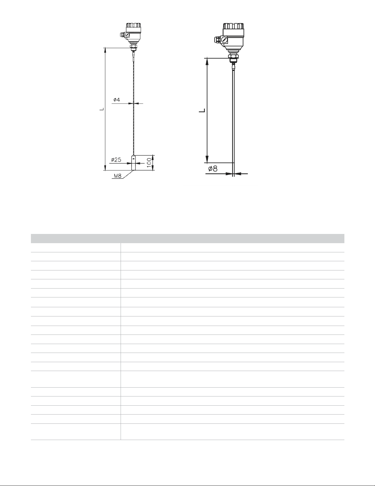
Dimensions
Type 2291 Cable Version
L = 6 m (19.69 ft)
Type 2291 Rod Version
L = 2 m (6.56 ft)
Specifi cations
General
Measured Values Level, Distance; Calculated values: Volume, Mass
Measuring Range Depends on the probe type and dielectric constant (ε
Probe Types Mono cable, mono rod
Accuracy: Linearity Error
1
For liquids: ± 5 mm (0.2 inch), if probe length ± 10 m (32 feet): ± 0.05 % of the probe length
Accuracy: Resolution ± 3 μA
Minimal ε
of the Medium 1.9
r
Power Supply 18 V… 35 V DC
Output: Digital Communication 4-20 mA + HART
Output: Display Graphical LCD display unit
Medium Temperature -30 °C… +90 °C (-22 °F… +194 °F),
Maximum Medium Pressure 4 MPa (40 bar g/ 580 psi g); with plastic lined fl ange: max. 2.5 MPa (25 bar g/ 363 psi g)
Ambient Temperature -20 °C… +60 °C (-4 °F… +140 °F)
Process Connection 1” BSP, 1” NPT Thread
Ingress Protection IP 67
Electrical Connection 2x M20x1.5 cable glands + internal thread for 2x ½”NPT cable protective pipe, cable outer
diameter: Ø 7 … Ø 13 mm (0.3 … 0.5 inch), wire cross section: max. 1.5 mm2 (AWG 15)
Electrical Protection Class III
Housing Material Plastic (PBT)
Sealing FPM, On request: FFKM, EPDM
Mass (head unit) 1.5 kg (3.3 lb)
EX-Approvals ATEX (ia): II 1/2 G Ex ia IIB T6…T5 Ga/Gb
ICEX (ia): EX ia IIB T6…T5 Ga/Gb
) of the measured medium
r
1
Under reference conditions and stabilized temperature
www.gfsignet.com
Page 3

Probe specifi cations*
Probe Type Max. Measuring
Dead-zone
2
Process Connection εr min.
Range
Upper (t)
/lower (b)
ε
= 80
r
Mono cable Ø 4 mm
(0.15 inch)
Mono rod Ø 8 mm
(0.3 inch)
*The unmeasurable upper and lower part of the tank. The lower dead zone is extended by the length of the counterweight (cable versions only).
6 m (19.6 feet) 300 /20 mm
(12 / 0.75 inch)
2 m (6.56 feet) 300 /20 mm
(12 / 0.75 inch)
Upper (t)
/lower (b)
ε
= 2.4
r
400 / 100 mm
(16 / 4 inch)
400 / 100 mm
(16 / 4 inch)
1” 1.9
1” 1.9
Technical data of the probes
Cable Rod
Max. meas. dist. 24 m (80 feet) 3 m (10 feet)
Min. meas. Dist. (ε
Minimal medium ε
= 80 / εr = 2.4) 0.3 m / 0.4 m (1 feet / 1.3 feet)
r
r
1.9
Sensing space around the probe Ø 600 mm (2 feet)
Process connection 1” BSP, 1” NPT
Probe material 1.4401 (316) 1.4571 (316 Ti)
Probe nominal Ø 4 mm (0.15 inch) 8 mm (0.3 inch)
Mass 0.12 kg/m (0.08 lb/ft) 0.4 kg/m (0.25 lb/ft)
Counterweight dimensions Ø 25x100 mm (1x4 inch) -
Counterweight material 1.4571 (316 Ti) -
2
The unmeasurable upper and lower part of the tank, the lower dead-zone is extended with the length of the counterweight (cable version)
Installation
The probes can be removed from the head unit by the user.
s = minimum distance from the internal disturbing objects.
Objects that are parallel to the probe do not disturb the
measurement. s > 300 mm (12 in.), h ≤ d, t
www.gfsignet.com
Page 4

Wiring
Display unit
connector
To Power Supply / HART Modem
Standard wiring & connection of HART-Modem
V
200mV
Loop current
measuring connector
U
1/2” NPT
M20x1,5
234561
GND
4...20 mA
1/2” NPT
M20x1,5
and supply
loop curren
(HART)
2312
-
+
To i-Go Converter - S3L / 4 to 20 mA
9900 Transmitter
8058-3
Signal
S3L/Freq
Converter
Black
Red
White
Black
SHLD
DATA
GND
V+
9900 S3L
Terminal
9900
Power
Input
Jump
PWR+
PWR–
LOOP+
LOOP–
Red
+
12 to 24 VDC
Black
Power Supply
–
Jumper from
PWR+ to LOOP+
2291 Radar
Level Sensor
E
250 Ohm
24V
A
HART
t
Wiring in an EX-environment
3
2
Ex Non Ex
Ex power
supply
3
2
Pin No. Assignment
1 Not Assigned
2 (+) Voltage measuring connector (200 mV)
3 (-) 4-20 mA loop current + supply (HART)
4 (+) 4-20 mA loop current + supply (HART)
5 (-) Voltage measuring connector (200 mV)
6 Not Assigned
Black
Red
Ordering Information
Mfr. Part No Code Description
2291-S-1DB1-6-R 159 300 190 LCD, PBT housing, 1" BSP, 6m cable Ø 4mm, SS316 Ti
2291-S-1DN1-6-R 159 300 191 LCD, PBT housing, 1" NPT, 6m cable Ø 4mm, SS316 Ti
2291-S-1DB1-2-D 159 300 192 LCD, PBT housing, 1" BSP, 2m rod Ø 8mm, SS316 Ti
2291-S-1DN1-2-D 159 300 193 LCD, PBT housing, 1" NPT, 2m rod Ø 8mm, SS316 Ti
Accessories
Mfr. Part No Code Description
3-8058-3 Special Order Wire-mount Signet i-Go signal (4 to 20 mA /S
3-8058-2 159 000 967 DIN rail mount Signet i-Go (4 to 20 mA/S
3-9900-1P 159 001 695 9900 Transmitter - Panel Mount
3-9900-1 159 001 696 9900 Transmitter - Field Mount
3-9950-1 159 001 841 9950 Base Unit – Two Channel Multi-Parameter Inputs, Two 4 to 20 mA Outputs,
3-9950-2 159 001 842 9950 Base Unit – Two Channel Multi-Parameter Inputs, Two 4 to 20 mA Outputs,
Rev B (03/18)
123456
159 300 181 HART - USB Modem
9900 Smart Pro, 8900 Multi-Parameter Controller. Single input.
9900 SmartPro, 8900 Multi-Parameter Controller. Two inputs.
Panel Mount, DC Power
Panel Mount, AC or DC Power
3
L) converter to connect 2290 to
3
L) converter to connect 2290 to
 Loading...