

Page 1
Instruction manual
2260 Ultrasonic Level
Transmitter
Page 2

Page 3

Content
1. Safety and responsibility .............................................................................................................................. 3
1.1 Intended use ............................................................................................................................................... 3
1.2 Safety regulations for the Ex approved units ............................................................................................ 3
2. Transport and storage .................................................................................................................................. 3
3. Design and function ...................................................................................................................................... 3
3.1 Design ......................................................................................................................................................... 3
3.2 Function ...................................................................................................................................................... 4
3.3 Basic concepts and elements of the ultrasonic measurement............................................................... 4
3.4 Identification ............................................................................................................................................... 5
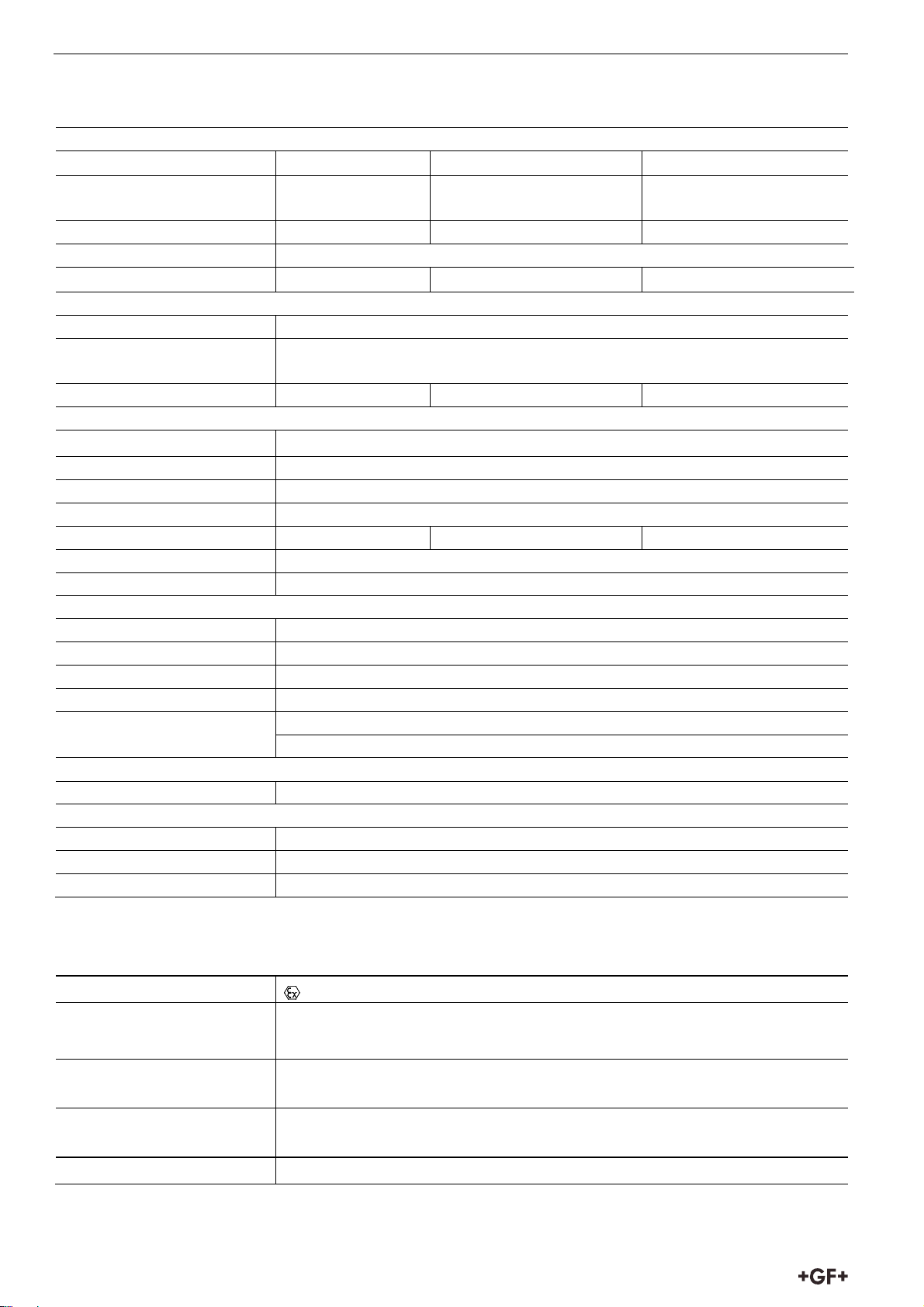
4. Technical Data .............................................................................................................................................. 6
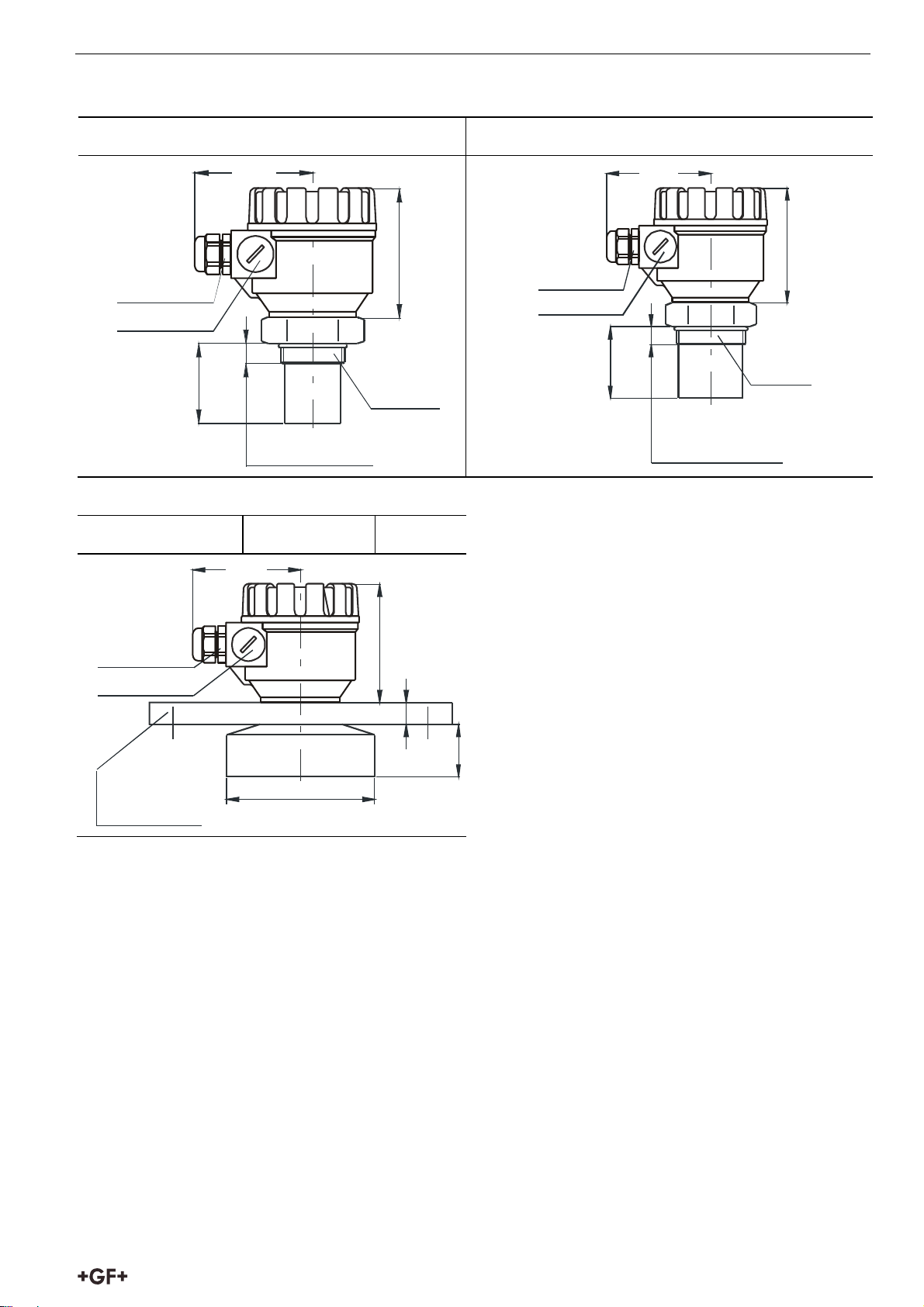
4.1 Dimensions ................................................................................................................................................. 7
4.2 Scope of delivery ........................................................................................................................................ 7
4.3 Maintenance and repair ............................................................................................................................. 7
5. Installation .................................................................................................................................................... 8
5.1 Liquid Level Measurement ........................................................................................................................ 8
5.2 Installation and electrical connection ..................................................................................................... 10
5.2.1 Details electrical connection............................................................................................................. 11
5.3 Loop current checking ............................................................................................................................. 12
6. Programming in general ............................................................................................................................ 13
6.1 Programming without display module .................................................................................................... 13
6.1.1 Procedure of programming .............................................................................................................. 14
6.1.2 Minimum level, (0%, empty tank) assignment to 4 mA ................................................................... 14
6.1.3 Maximum level (100%, full tank) assignment to 20 mA .................................................................. 14
6.1.4 “Error state” indication by the analogue signal ............................................................................... 14
6.1.5 Damping time setting ........................................................................................................................ 15
6.1.6 RESET: Returning to the default ....................................................................................................... 15
6.1.7 Indication of mistakes (by LEDs) made during programming ........................................................ 15
6.2 Programming with the Display Module .................................................................................................. 16
6.2.1 Display Module ..........................................................................................................
6.2.2 Steps of the Display Module .............................................................................................................. 17
6.2.3 Indications of the DISPLAY MODULE and LED Status ..................................................................... 18
6.2.4 QUICKSET ........................................................................................................................................... 19
6.2.5 Full parameter access ...................................................................................................................... 20
......................... 16
7. Parameters – Description and Programming ........................................................................................... 22
7.1 Measurement configuration .................................................................................................................... 22
7.2 Current output .......................................................................................................................................... 26
7.3 Measurement optimisation ...................................................................................................................... 27
7.4 Volume Measurement .............................................................................................................................. 30
1
Page 4

Instruction for use Safety and responsibility
7.5 Volume Flow Measuring .......................................................................................................................... 31
7.5.1 Open Channel Flow Measurement ................................................................................................... 31
7.6 32-Point-Linearisation ............................................................................................................................. 34
7.7 Informational parameters (read out parameters) .................................................................................. 36
7.8 Additional parameters of the flow metering .......................................................................................... 37
7.9 Test parameters ....................................................................................................................................... 37
7.10 Simulation ............................................................................................................................................... 38
7.11 Access Lock ............................................................................................................................................ 38
8. Error Codes ................................................................................................................................................ 39
9. Parameter table ......................................................................................................................................... 40
10. Sound velocities in different gases .......................................................................................................... 42
11. Article overview ........................................................................................................................................ 42
12. Disposal .................................................................................................................................................... 43
2
Page 5
Safety and responsibility Instruction for use
1. Safety and responsibility
1.1 Intended use
The 2260 Ultrasonic Level Transmitters are an excellent tool for the level measurement of liquids. Level
measurement technology based on the non-contacting ultrasonic principle is especially suited for
applications where, for any reason, no physical contact can be established to the surface of the material
to be measured. Such reasons may include corrosive attack by the process medium against the
measuring device material (acids), possible contamination (sewage) or particles of the process medium
adhering to the measuring device (adhesive materials).
1.2 Safety regulations for the Ex approved units
The 2260 Ultrasonic Level Transmitter must be operated in intrinsically safe circuit only, see values in
chapter “Technical Data”. For temperatures see values in “Techical Data”. Transducer head are made of
plastic tending to charge up electrostatically, thus:
The velocity of the filling and discharging process must be chosen according to the medium.
During filling the material causing the hazard must be hindered from forming a mist
It is not permitted to clean the plastic cover in explosion hazardous area
The apparatus is not suitable for flame-proof enclosure towards the external area.
2. Transport and storage
Transport and/or store product in unopened original packaging.
Protect product from dust, dirt, dampness as well as thermal and UV radiation.
Make sure that the product has not been damaged neither by mechanical nor thermal influences.
Check product for transport damages prior to the installation.
3. Design and function
3.1 Design
3
Page 6
Instruction for use Design and function
3.2 Function
The ultrasonic level metering technology is based on the principle of measuring the time required for the
ultrasound pulses to make a round trip from the sensor to the level to be measured and back. The sensor
emits an ultrasonic pulse train and receives the echoes reflected. The intelligent electronic device
processes the received signal by selecting the echo reflected by the surface and calculates from the time
of flight the distance between the sensor and the surface which constitutes the basis of all output signals
of the 2260 Ultrasonic Level Transmitter.
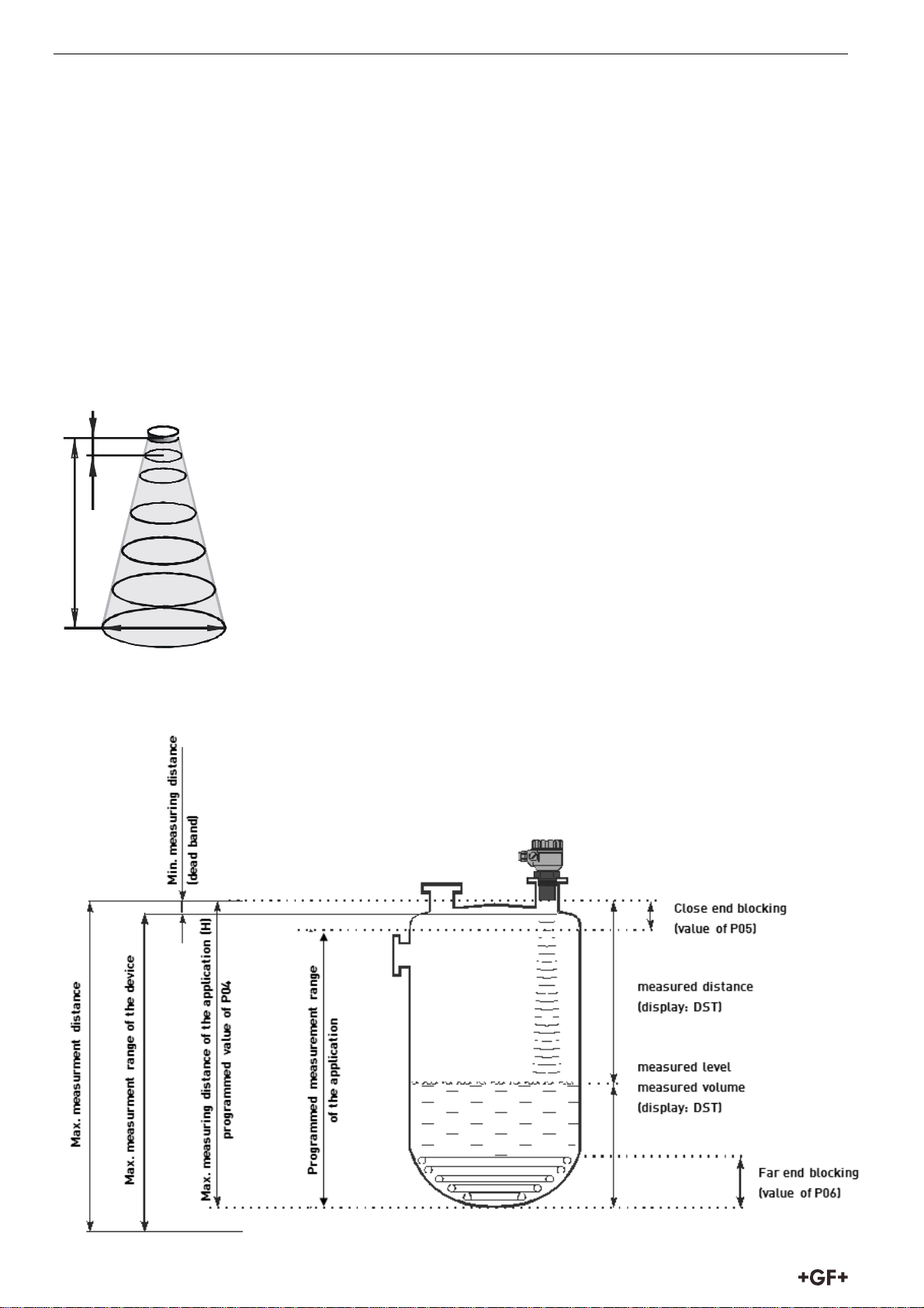
A Total beam angle of 5°-7° at –3 dB as is featured by transducers of transmitters and sensores ensuring
a reliable measurement in narrow silos with uneven side walls as well as in process tanks with various
protruding objects.
Furthermore, as a result of the narrow beam angle - the emitted ultrasonic signals have an outstanding
focusing - deep penetration through gases, vapour and foam is ensured.
XD
1 m 0,2 1 m
2 m 0,3 m
m
X
M
X
5 m 0,56 m
10 m 1 m
15m 1,45 m
rr
D
Diameters corresponding to 5° beam angle.
3.3 Basic concepts and elements of the ultrasonic measurement
4
Page 7
Design and function Instruction for use
Minimum measuring distance (Xm) (Dead Band) is determined by the design of the unit within which the
measurement is not possible (Dead Zone). This distance can be extended by programming in order to
avoid disturbing effects of possible disturbing echoes coming from fixed objects. (Close-end Blocking)..
Maximum measuring distance (X
) is the greatest distance (determined by the design of the unit) which
M
can be measured by the unit under ideal conditions. The maximum measuring distance of the actual
application (H) must not be greater than X
.
M
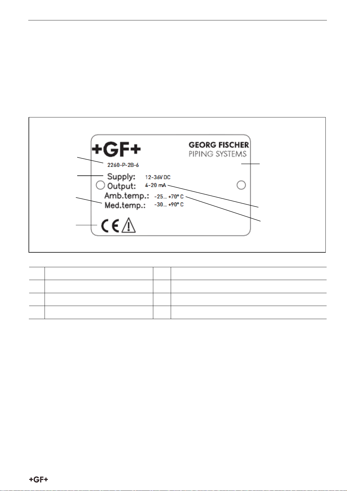
3.4 Identification
1
M226193
5
2
3
6
4
7
Type
1
Media temperature
2
Voltage
3
CE-marking
4
5
6
7
Serial code
Output
Ambient temperature
5
Page 8
Instruction for use Technical Data
4. Technical Data
General
Type
Range 0.2 to 4 m / 0.65 to
Total Beam Angle 6° 5° 5°
Accuracy * ± (0.2 % of measured distance, 0.05 % of range)
Measuring freq. 80 kHz 80 kHz 40 kHz
Enviromental
Process temperature -30° bis +90°
Process pressure
(absolute)
Process connection 1 ½ in. BSP / NPT 2 in. BSP / NPT DN125 flange
Enclosure
Enclosure Material
- Sensor Body PP or PVDF
- Housing PBT
Resolution <2m: 1 mm2 to 5 m: 2 mm 5 to 10 m: 5 mm >10m: 10 mm
Ingress protection
- Sensor Body IP 68, NEMA 6P
- Housing IP 68, NEMA 6P
Electrical
Outputs 2- wire 4–20 mA, HART protocol, max. 600 ohm
Relay (SPDT) 250V AC, 3A AC1
Power Supply 1 to 36 VDC / 44 to 800 mW
Power Consumption DC 3.6 W, AC 4 VA
Connection 2 x M20 x 1,5 plastic cable gland: Cable: Ø6 to 12 mm
Standards and Approvals
ATEX Approval ATEX II 1 G EEx ia II B T6 (available for 2-wire SP series only)
Display Module
Field indication 6 digits Custom LCD, icons and bargraph
Ambient temperature -25°C … +70°C
Housing material PBT, low inflammability (DuPont®)
* Under optimal circumstances of reflection and stabilised transducer temperature
Additional data for EX certified devices
Ex marking
2260-X-XXX-4 2260-X-XXX-6 2260-X-XXX-15
0.25 to 6 m / 0.82 to 20 ft * 0.45 to 15 m / 1.5 to 49 ft
13 ft *
*
0.03 to 0.3 MPa (0.3 to 3 bar)
Ex-version: 2 x M20x1,5 metal cable gland: Cable: Ø7 … 13 mm
II1G EEx ia IIB T6 IP68
Intrinsically safety data
≤ 15 nF, Li ≤ 200 H, Ui ≤ 30 V, Ii ≤ 140 mA, Pi ≤ 1 W
C
i
Ex-device should be powered by EEx ia power supply.
Ex power supply, loading
Medium temperature
< 30 V, I0 < 140 mA, P0 < 1 W, Voltage range 12…30 V,
U
0
= (Us – 12 V) / 0,02 A
R
t max
For PP transducer –20 °C ... +70 °C, for PVDF transducer –20 °C ... +80
°C, for PTFE transducer –30 °C ... +90 °C
Ambient temperature -20 °C … +70 °C
6
Page 9
Technical Data Instruction for use
g
g
4.1 Dimensions
Version 1 ½” BSP/ NPT Version 2” BSP/ NPT
~89
97.5
~60
BSP len
NPT len
2" BSP
or NPT
th 15
th 22
2 x M20x1.5
2 x 1/2" NPT
~89
97.5
2 x M20x1.5
2 x 1/2" NPT
~60
BSP length 15
NPT length 22
1 1/2" BSP
or NPT
Version Flange connection
Type Process xxx Range
~89
2 x M20x1. 5
2 x 1/2" NPT
*
DIN DN125 PN16
ANSI 5" 150 psi
JIS 10K 125A
122
97.5
19
~43
* Min. Flange size
4.2 Scope of delivery
2 x M20x1.5 cable gland
Installation and Programming Manual
Display Module
4.3 Maintenance and repair
The 2260 Ultrasonic Level Transmitters do not require maintenance on a regular basis. In some very rare
instances, however, the transducer may need a cleaning from deposited material. This must be carried
out gently, without scratching or pressing the surface of the transducer.
Repairs during or after the warranty period are carried out exclusively at the Manufacturers. The
equipment sent back for repairs should be cleaned or neutralised (disinfected) by the User.
7
Page 10
Instruction for use Installation
5. Installation
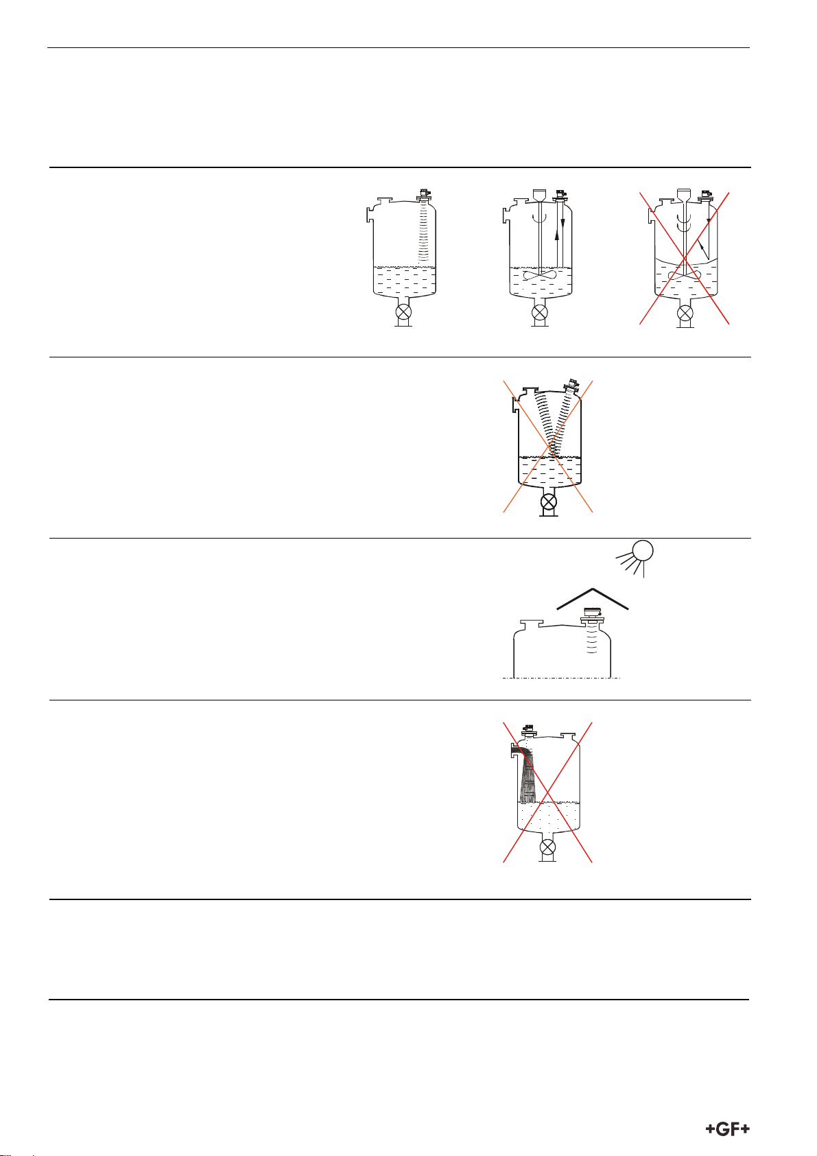
5.1 Liquid Level Measurement
Position
The optimal position of the 2260 Ultrasonic
Level Transmitter is on the radius
r = (0.3 … 0.5) R of the (cylindrical) tank / silo.
(Take also sonic cone on page 1 into
consideration.)
Sensor alignment
The sensor face has to be parallel to the surface of the liquid
within ± 2-3°.
Temperature
Make sure that the 2260 Ultrasonic Level Transmitter will be
protected against overheating by direct sunshine.
Sonnenschirm
Obstacles
Make sure that no in-flow path or objects (e.g. cooling pipes,
ladders, bracing members, thermometers, etc.) or no tank wall of
the ragged surface protrude into the sensing cone of the
ultrasonic beam.
One fix object in the tank / silo that disturb the measurement can
be blocked out by the appropriate programming of the 2260
Ultrasonic Level Transmitters – see Parameter P29 “Blocking out
of disturbing object”
Foam
Foaming of the liquid surface may render ultrasonic level metering impossible. If possible, a location
should be found, where foaming is the least (device should be located as far as possible from liquid
inflow) or a stilling pipe or well should be used.
8
Page 11
Installation Instruction for use
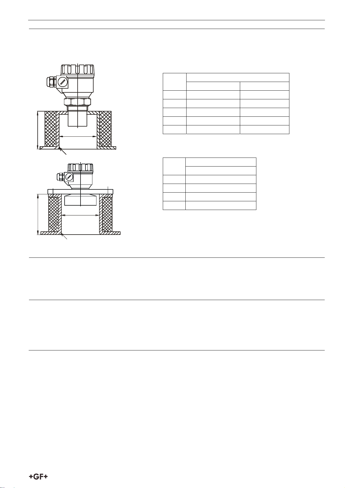
Stand-off-Pipe
The structure of the stand off pipe should be rigid; the inner rim where the ultrasonic beam leaves the
pipe should be rounded.
L D
min
BSP/ NPT 1 ½” BSP/ NPT 2”
150 50 60
200 50 60
250 65 65
300 80 75
L
Ø D
350 95 85
r
L D
min
Flange connection
90 130 mm
200 140 mm
350 150 mm
500 160 mm
L
Ø D
r
Note: The mentioned values are indications.
Depending on the assembling conditions larger
diameters are to be considered.
Wind
Intensive air (gas) movements in the vicinity of the ultrasonic cone is to be avoided. A strong draft of
wind may "blow away" the ultrasound. Devices with lower measuring frequency (40, 20 kHz) are
recommended.
Fumes/ Vapours
For closed tanks containing chemicals or other liquids, which creats fume/gases above the liquid
surface especially for outdoor tanks exposed to the sun, a strong reduction of the nominal measuring
range of the ultrasonic device is to be considered during device selection.
Devices with lower measuring frequency (40, 20 kHz) are recommended in these cases units.
9
Page 12
Instruction for use Installation
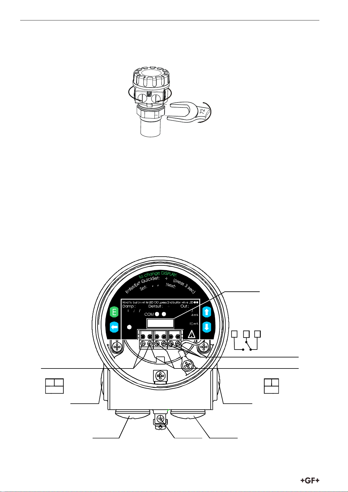
5.2 Installation and electrical connection
5.2.1 Installation of the (BSP or NPT) threaded models
Screw the unit in to its place. Use open wrench for tightening; max torque is 20Nm
2
1
After tightening the enclosure can be rotated to the proper position. (Safety bolt prevents rotation
more than 350°)
The unit may be damaged by electrostatic discharge (EDS) via its terminal, thus apply the
precautions commonly used to avoid electrostatic discharge e.g. by touching a properly grounded
point before removing the cover of the enclosure.
Ensure that the power supply is turned off at the source.
With removal of the cover of the housing and taking out the display module (if any), the screw
terminals can be accessed. Suggested cable core cross section:
0.5 ... 1.5 mm
Switch on the unit and make necessary programming.
After programming ensure proper sealing and closing of the cover.
2
. Arrange grounding by the inner or outer grounding screw first.
Display unit
connector
VALID
RELAY
54 6
(Only normal
C1
version)
Connect or for
meas. of loop current
1
23456
C2
4...20 mA loop current
and suppl.voltage (HART)
2 31 2
U
1/2 ” N PT
1/2” NPT
I
M20x1,5
10
GND
M20x1,5
Page 13
Installation Instruction for use
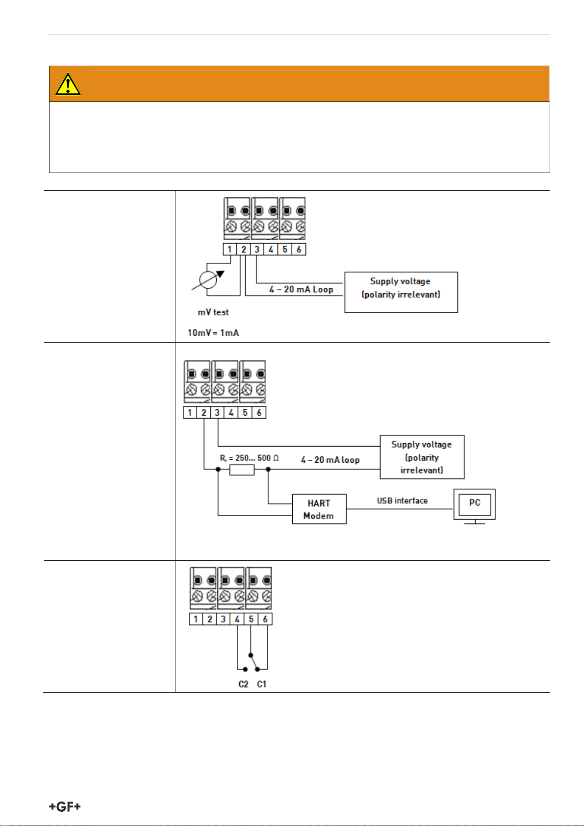
5.2.2 Details electrical connection
WARNING
Risk of personal injury and damage of the product!
Damage due to supplying the terminals 1 and 2.
Make sure that terminals 2 and 3 are supplied.
Connection 4 -20 mA +
test output
Connection 4 – 20mA +
HART
For questions on HART Modem: Contact representative of GF Piping
Systems.
Connection internal
relais
11
Page 14
Instruction for use Installation
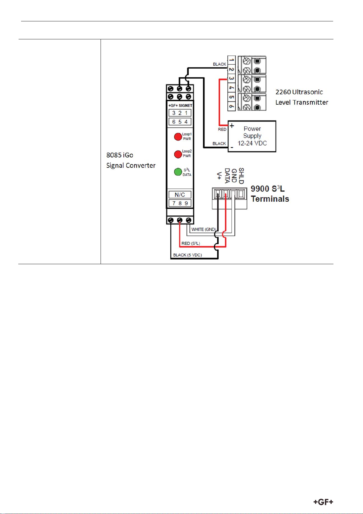
Connection 9900
Universal Transmitter
5.3 Loop current checking
After removing the cover and the Display Module the actual loop current can be measured with an
accuracy of 0.5% by connecting an voltmeter (in the range of 200 mV) to the terminals indicated on the
drawing above.
12
Page 15
Programming in general Instruction for use
6. Programming in general
The 2260 Ultrasonic Level Transmitters can be programmed by the following two ways:
1. Programming without Display Module, see 6.1
Assignment of the levels to the 4 and 20 mA current output, error indication by the analogue signal
and damping can be set.
2. With Display Module, see 6.2
All features of the unit can be set, such as measurement configuration and optimisation, 32-point
linearisation, dimensions for 11 tanks with different shape and for 21 different open channels (flume,
weir, etc).
The devices are already equipped with the display module. The 2260 Ultrasonic Level Transmitter is fully
operational without the display module. It is only needed for programming and/or displaying
measurement values.
The unit will measure during programming in accordance with the previous parameters. The new,
modified parameters will only be effective after returning to the Measurement Mode
If the 2260 Ultrasonic Level Transmitter is left in Programming Mode by mistake, it will
automatically return to Measurement Mode after 30 minutes and will operate with the
parameters entered during the last completed programming. The 2260 Ultrasonic Level
Transmitter will be delivered with the following Factory Default:
• Current output, display and bargraph: LEVEL
• 4 mA: assigned to the minimum level 0%
• 20 mA: assigned to the maximum level 100%
• Error indication by the current output: hold last value
• Damping: 60 sec
6.1 Programming without display module
Programming is only possible if the 2260 Ultrasonic Level Transmitter is in Level Measuring Mode and
receives valid echo i.e. “VALID” LED is lit. The following can be programmed without display module:
Assignment of the 4 mA to a required e.g. min. level / max.
distance
Assignment of the 20 mA to a required e.g. max. level /
min. distance
Error indication by the current output (Hold, 3.6 mA or
22 mA)
Damping (10, 30 or 60 sec)
Reset to the factory default
Note: Current output can also be assigned in inverted mode:
4 mA = 100% (Full), 20 mA = 0% (Empty)
13
Page 16

Instruction for use Programming in general
6.1.1 Procedure of programming
Press button in the relevant sequence and check the state of the LED-s. Symbols for the states of the
LED-s:
= LED is off, = LED is blinking, = LED is on, = LEDs are blinking alternatively
= Dont care
6.1.2 Teach-in: Minimum level, (empty tank) assignment to 4 mA
Action LED state following the action
Check for a valid
1)
ECHO
2)
Press NEXT
button steadily
3)
Press up button
steadily
4)
Release buttons
= Valid ECHO, transmitter
programmable
= 2260 Ultrasonic Level
Transmitter in programming
mode
= 4 mA assigned to the distance
(see picture)
= Programming completed
B
Use level in tank or a fix target e.g.
the wall
6.1.3 Teach-in: Maximum level (full tank) assignment to 20 mA
Action LED state following the action
Check for a valid ECHO
1)
Press NEXT button
2)
steadily
Press DOWN button
3)
steadily
Release buttons = Programming completed
4)
= Valid ECHO, transmitter
programmable
= 2260 Ultrasonic Level
Transmitters in programming
mode
= 20 mA as signed to the distance
(see picture)
Use level in tank or a fix target
e.g. the wall
B
B
B
6.1.4 “Error state” indication by the analogue signal
(Check for a valid echo as above)
As a result of this setting the value of the analogue output will be 3.8 mA; 22 mA or according last value
(hold) until the error is ceased.
Action LED state following the action
1)
Press
Press any of the DOWN
2)
NEXT
Release buttons = Programming completed
3)
button steadily
, ENTER E,
buttons steadily
= 2260 Ultrasonic Level Transmitters in
programming mode
– hold last value
= – 3.6 mA
– 22 mA
14
Page 17

Programming in general Instruction for use
6.1.5 Damping time setting
(Check for a valid echo as above)
Action LED state following the action
1)
Press ENTER
E
button steadily
= 2260 Ultrasonic Level Transmitter in
programming mode
2)
Press any of the NEXT
DOWN
Release buttons = Programming completed
3)
buttons steadily
, UP ,
– 10 sec
= – 30 sec
– 60 sec
6.1.6 RESET: Returning to the default
(Check for a valid echo as above)
Action LED state following the action
1)
Press NEXT button steadily
= 2260 Ultrasonic Level Transmitter in
programming mode
2)
Press ENTER E button steadily
= Default loaded
6.1.7 Indication of mistakes (by LEDs) made during programming
Action Led state following the action Possible correction
Attempted programming = blinking twice = no Echo Find a valid Echo
Attempted programming = blinking three times = no access
possible
= blinking four times = 2260
Attempted programming
Ultrasonic Level Transmitter not
in Level Measurement Mode
With DISPLAY MODULE only
See 5.2 (P99)
With DISPLAY MODULE only
See 5.2 (P01)
15
Page 18

Instruction for use Programming in general
6.2 Programming with the Display Module
The 2260 Ultrasonic Level Transmitter should be adjusted to the process by programming the
parameters. The Display Module can be used to display the parameters during programming and
measurement values during measurement. The DISPLAY MODULE supports two separately accessible
programming modes representing 2-layers of programming complexity, depending on user choice.
PLUG-IN DI SPL AY MODULE
FULL
QUICKSET
see capter 6.2.4 see chapter 6.2.5
QUICKSET
Recommended as a simple and fast way to set up the 2260 Ultrasonic Level Transmitter, see „Quick Set
Manual” at the beginning of this document. Qucikset by 6 basic parameters for the following basic settings,
marked by abbreviations easy to remember:
Engineering unit for the display (Metric or US)
Maximum measuring distance (H)
Assignment of min level to 4 mA
Assignment of max level to 20 mA
Error indication by the current output
Damping time
Full Parameter Access
All features of the 2260 Ultrasonic Level Transmitter such as:
Measurement configuration
Outputs
Measurement optimisation
11 pre-programmed tank shapes for volume calculation
21 pre-programmed formula for flow metering
32-point linearisation
PARAMETER
ACCESS
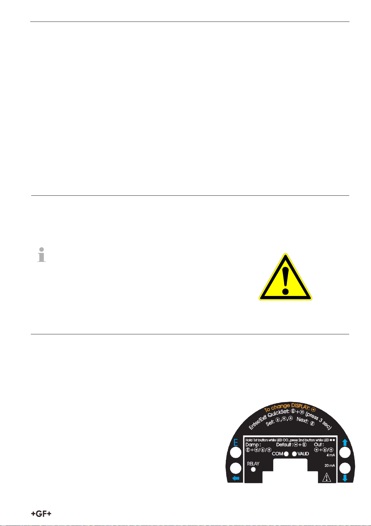
6.2.1 Display Module
Symbols used on the LCD
DIST – Distance (measuring) mode
LEV – Level (measuring) mode
VOL – Volume (measuring) mode
FLOW – Open channel (flow metering) mode
PROG - Programming mode
(device under programming)
RELAY – ‘C2’ circuit of the relay is closed
T1 - TOT1 volume flow totaliser
(resetable aggregate)
T2 - TOT2 volume flow totaliser (aggregate)
FAIL - Measurement / device error
- Level changing direction
Bargraph assigned to the current output or echo strength
16
Page 19

Programming in general Instruction for use
yy
Symbols used on the frame
M – Metric system
US – US calculation system
LEDs lit
COM – digital (Hart) communication
VALID – presence of valid echo
IrDA – Infrared communication port for logger readout,
diagnostics and software upgrade.
6.2.2 Steps of the Display Module
Programming will be performed by the pressing and releasing the relevant one or two keys
(simultaneously).
Single key pressing
ENTER
to save parameter value and return to parameter address
E
to select parameter address and go to parameter value
NEXT
UP
DOWN
to move the blinking (sign of change) of the digit to the left
to increase value of the blinking digit
to decrease value of the blinking digit
:xxxx
yy parameter address (P01, P02…P99)
xxxx parameter value (dcba)
bargraph
Double key pressing
Press the two keys simultaneously for desired programming step.
Enter into or quit programming
modes
E
r
e
t
e
s
m
s
a
e
r
c
a
c
P
A
l
l
u
F
Q
u
i
c
k
s
e
t
Basic steps while parameter
address is blinking
E
f
i
d
o
m
l
l
a
l
e
c
n
a
C
Return to default*
* LOAD readout ** CANCEL readout
*
*
s
n
o
i
t
a
c
i
GET LEVEL function
Basic steps while parameter
value is blinking
e
u
l
a
v
t
l
r
u
e
t
a
f
e
e
m
D
a
r
a
P
E
c
i
f
i
d
o
m
l
r
l
e
a
t
l
e
e
m
c
a
n
r
a
a
C
p
o
t
n
r
u
t
e
r
Display defa ult valu e
* cancellation imme diately activ e
e
u
s
n
o
i
t
a
s
s
e
r
d
d
a
l
a
*
v
l
r
a
e
t
u
t
e
c
m
A
a
r
a
P
Special function used only in level and distance measurement modes
Notes. If after pressing ENTER
E
blinking does not spring over from the parameter address to the
UP
+ DOWN
parameter value this means that
the parameter is either a read-out type, or
the secret code prevents the modification (see P99)
If the modification of the parameter value is not accepted i.e. the parameter value keeps blinking after
E
pressing ENTER
,
the modified value is either out of the range, or
the code entered is not a valid code
17
Page 20

Instruction for use Programming in general
6.2.3 Indications of the DISPLAY MODULE and LED Status
LED indication
VALID (ECHO)-LED lit in
case of valid echo.
COM-LED see description of
HART
RELAY-LED ON – when the
‘C2’ circuit of the relay is
closed
(Vol/Flow)
See
P01
for possible readouts
(Distance)
(Error)
DISPLAY MODULE
indications
Depending on the
measurement one of the
below symbols will lit and
the process value displayed
(see P01 chapter 6.1).
Engineering units will be
indicated directly (°C, °F and
mA) and by the lit arrow
showing towards them on
the frame
DIST distance
LEV level
VOL volume
FLOW flow
T1/T2 totalised values
FAIL (blinking) Error code
displayed
For paging readouts NEXT
key should be pressed.
The following process values can be
displayed
Volume / Flow – if programmed so
Level – if programmed so
Distance – if programmed so
Warning indications – FAIL blinking
Display screens can be scrolled by
pressing key NEXT
.
To return to the screen of the selected
measurement mode key ENTER
E
should be pressed (see P01 chapter 6.1)
Temperature can be displayed by
pressing UP
.
(°C/°F)
Current output value can be displayed by
pressing DOWN
(mA)
.
18
Page 21

Programming in general Instruction for use
yy
6.2.4 QUICKSET
Recommended as a simple and fast way to start up
QUICKSET programming (aided by 6 screens) is used in uncomplicated level metering applications to set
the 6 basic parameters. The other parameters can only be modified in the
Full Parameter Access Mode (P01).The instructions of this programming mode are also to be found on
the front panel above the Display Module socket.
Keys Function
E
ENTER
+ DOWN
(press for min 3 secs!)
UP
UP
ENTER
NEXT +
, DOWN , NEXT
+ DOWN
E
UP
NEXT + DOWN
Screens Actions
plication
AP
xx= select “EU” (European) for metric or “US” for US engineering units
AP:xx
(Use UP /
yy= indicating “Li” for liquids
DOWN
DEFAULT: EU
Enter or exit QUICKSET programming mode
Increase/decrease and move left the blinking digit
“GET LEVEL" - display actual level measured by the 2260
Ultrasonic Level Transmitters
Save readout and step to the next screen
Quit Current Output Scaling without saving the
modifications (CANCEL))
Display of the DEFAULT value.
keys)
Programming of this parameter will result in loading the factory default
with the corresponding engineering units.
H:xxxx
H = xxxx
maximum measuring distance
– Distance between transducer face and
tank bottom
Manual: set value (Use UP
ENTER
E
)
/ DOWN / NEXT keys) and save it (by
Automatic: use the “GET LEVEL” function (UP
+ DOWN ) to obtain actual
measured value with level in tank or a fixed target, i.e. wall. (“GET LEVEL”
functions only if ECHO LED is lit) and save it as above.
DEFAULT: maximum measuring distance [m], see Technical Data Table
4 mA xxxx –
level value
assigned to 4 mA current output
4:xxxx
Manual: set level value (by UP
(by ENTER
E
)
/ DOWN / NEXT keys) and save it
Automatic: use the “GET LEVEL” function (UP
+ DOWN ) to display the
actual measured value with level in tank or a fixed target, i.e. wall. (“GET LEVEL”
functions only if ECHO LED is lit) and save it as above.
DEFAULT: 0 m (0%, Empty tank)
19
Page 22

Instruction for use Programming in general
yy
20:xxxx
20 mA xxxx –
Manual: set level value
(by ENTER
level value
E
)
assigned to 20 mA current output
(Use UP /
DOWN
Automatic: use the “GET LEVEL” function
/
NEXT
(UP +
keys)
DOWN
)
and save it
to obtain actual
measured value with level in tank or a fixed target, i.e. wall. (“GET LEVEL”
functions only if ECHO LED is lit) and save it as above.
DEFAULT: max. level = max. measuring distance – dead band [m] (100%, Full
tank) (See Technical Data Table)
Er:xxxx
Error indication by the current output – select “Hold”, 3.8 mA or 22 mA (by UP
DOWN
key) and save it as above.
DEFAULT: hold last value
dt: xxxx
amping time
d
as above.
: select required damping time (by UP
/
DOWN key) and save it
DEFAULT: 60 sec for liquids, 300 sec for solids
Note: Current output can also be programmed for inverted operation: 4 mA= 100% (Full), 20 mA= 0%
(Empty). Description of failures can be found under the chapter „Error codes”.
6.2.5 Full parameter access
Full Parameter Access is the highest programming level to access all features provided by the 2260
Ultrasonic Level Transmitters.
Description of all parameters can be found under the chapter “Parameter”.
Keys Function
E
ENTER
+ NEXT
(press for 3 seconds)
In this programming mode, the display will indicate
yy Parameter Address (P01, P02 … P99)
xxxx Parameter Value (dcba)
bar graph
Measuring is going on during programming in accordance with the old parameter set. New parameter
set will be valid after returning to the Measurement to the Programming Mode.
Enter or exit Full Parameter Access programming mode.
:xxxx
/
20
Page 23

Programming in general Instruction for use
Steps and indications of the Full Parameter Access programming mode
pressing Keys while Parameter Address is blinking while Parameter Value is
blinking
Save the modification of the
ENTER E
Go to the Parameter Value
Parameter Value and return to the
Parameter Address
NEXT + UP
NEXT + DOWN
NEXT
UP / DOWN
Cancel all modifications of the actual
programming phase. Pressing for 3 sec
is required while CANCEL will be
displayed for warning
Reset entire device to Factory Default.
Since this action will reset all
parameters, “LOAD” will appear on the
display:
- to confirm, press
- to escape, press any other key
- Exception: clearing TOT 1 (See at
parameter P77)
Move blinking (changeability) of the digit to the left
Modify the blinking digit (increase, decrease) or scroll up/down
Neglect the modification of the
Parameter Value.
and return to the Parameter
Address without saving the
modifications
Display default of the Parameter
Values (it can be saved by pressing
E
ENTER
)
21
Page 24

Instruction for use Parameters – Description and Programming
7. Parameters – Description and Programming
7.1 Measurement configuration
P00: - cba Application/ Enginnering Units
Programming of this parameter will result in loading the factory default with the corresponding
engineering units.
a Operating (measurement) mode
0 Liquid level measurement
b Engineering units
(according to “c”)
Metric
US
0 m ft
1 cm inch
c Calculation system
0 Metric
1 US
Factory Default: 000
P01: - ba Measurement Mode – Bargraph
Attention: mind the sequence!
When programming this parameter the
right value “a” will be blinking first.
Parameter value „a” will determine the basic measurement value that will be displayed and proportional
with the current output. Depending on the value of “a” process values as listed in the 3d column can also
be displayed by pressing NEXT
pressed.
. For return to the display of the basic value the ENTER E key should be
a Measurement
Mode
Display
symbol
Displayed values
0 Distance DIST Distance
1 Level LEV Level, Distance
2 Level in
LEV% Level%, Level, Distance
percentage
3 Volume VOL Volume, Level, Distance
4 Volume in
percentage
VOL% Volume%, Volume, Level,
Distance
Attention: mind the
sequence!
When programming this
parameter the
right value “a” will be
blinking first.
5 Flow FLOW Flow, TOT1, TOT2, Level,
Distance
Parameter value “b” will determine that the height of the Bargraph will be proportional to the current
output or to the Echo strength.
b Bargraph indication
0 Echo strength
1 Current output
Factory Default: 11
22
Page 25

Parameters – Description and Programming Instruction for use
P02: - cba Calculation units
a Temperature
0 °C
1 °F
When programming this parameter the right
Attention: mind the sequence!
value “a” will be blinking first.
.
This table is interpreted according to P00(c), P01(a) and P02(c) and is irrelevant in case of percentage
measurement ( P01(a)= 2 or 4 )
b Volume Weight (set also P32) Volume flow
Metric US Metric US Metric US
0 m3 ft3 - lb (pound) m3/time ft3/time
1 liter gallons tons tons liter/time gallons/ti
c Time
me
0 Sec
1 Min
2 Hour
3 Day
Factory Default: 000
P03: - - - a Values displayed - Rounding
It is important to keep in mind that the instrument is measuring distance.
Measured
Resolution
Distance
X
– 2m 1mm
min
2m – 5m 2mm
5m – 10m 5mm
10m over 10mm
The resolution depending on the distance can be
considered as a kind of rounding that will be
contained in all further value (of level, volume or
volume flow) calculated. Therefore if programmed for
DIST or LEV measurement the setting of P03 is
irrelevant.
Displayed VOL or FLOW
Angezeigter Wert Anzeigeformat Obviously the decimal position will be shifted with
0,000 – 9,999 x,xxx
10,000 – 99,999 xx,xx
100,000 – 999,999 xxx,x
1000,000 –
xxxx,x
9999,999
10000,000 –
xxxxx,x
increasing value displayed. (See table at the left).
Values over one million will be displayed in
exponential format whereas the value (e) represents
the exponent. Over the value of 1x10¹⁰ Err4 (overflow)
will be displayed.
99999,999
100000,000 –
xxxxxx,x
999999,999
1 millió –
9
9,99999*10
Über 1*10
10
(overflow) Err4
x,xxxx : e
(exponential
format)
23
Page 26

Instruction for use Parameters – Description and Programming
Rounding
Parameter Value
“a”
Steps In The
Displayed Value
0 1 (no rounding)
1 2
2 5
3 10
4 20
5 50
A couple of millimetres of fluctuation of the basic DIST
value (e.g. due to waves) will be enlarged by the
mathematical operations. This enlarged fluctuation in
displaying VOL or FLOW can (if disturbing) be avoided by
rounding to be set in P03. Rounding value 2, 5, 10 etc
represents the steps by which the calculated value will
be changed in its (one or two) last digit(s).
Examples:
P03=1 steps by 2: 1,000; 1,002; 1,004
P03=5 steps by 50: 1,000; 1,050; 1,100 or 10,00;
10,05(0); 10,10(0); 10,15(0)
(the 0 from the steps 50, 100, 150 etc will not be
displayed)
Factory Default: 0
P04 Maximum Distance to be Measured (H)
The maximum distance to be measured is the greatest distance between the surface of the transducer
and the level to be measured.
This is the only parameter that has to be programmed for each application other than distance
(however to avoid disturbing effect of possible multiple echos it is suggested to do this in distance
measurement applications too).
Values of the maximum measuring distance will be displayed as below:
Engineering Unit Display Format
m x,xxx or xx,xx
cm xxx,x
ft xx,xx or xxx,x
inch xxx,x
The factory programmed, greatest distances (DEFAULT values) which can be measured by the units are
listed in the table below. For the actual application the maximum distance to be measured i.e. the
distance between the sensor and the bottom of the tank should be entered in P04.
To obtain the best accuracy, measure this distance in the empty tank with the 2260 Ultrasonic Level
Transmitters by using the “GET LEVEL” function (by double key pressing of UP
+ DOWN ) provided
the bottom is flat. Enter the actual measured value displayed as P04.
2260 Ultrasonic
Level Transmitters
Transducer material
PP / PVDF
Version I 4/13
Version II 6/20
Version III 15/49
Maximum measuring distance m/ft
Factory Default: according to the table
24
Page 27

Parameters – Description and Programming Instruction for use
P05: Minimum measuring distance (Dead zone- Close-end blocking)
The 2260 Ultrasonic Level Transmitters will not accept any echo within the
blocking distance set here.
Automatic Close-end-blocking (Automatic Dead Band control)
By using the factory default value, the unit will automatically set the smallest possible close-endblocking distance i.e. the dead band.
Manual close-end-blocking
Manual close-end-blocking should be used for example to block out the echo originating from the bottom
rim of a stand-off pipe or from any object protruding into the ultrasonic cone near to the transmitter.
By entering a value, higher than the factory default, the minimum measuring range will be extended and
fixed to the specified value.
To return to the factoryprogrammed (DEFAULT value) of the minimum measuring distance press
NEXT
+ DOWN
2260 Ultrasonic
Level Transmitters
Minimum measuring distance X
Sensor material
[m/ft]
M
PP / PVDF
Version I 0,2 / 0,65
Version II 0,25 / 0,82
Version III 0,45 / 1,5
Factory Default: automatic dead band control
P06: Far end blocking
Far end blocking is used to neglect incorrect
level/volume readings and output actions below a
A
A
m
A
m
m
0
2
4
pre-set level programmed in P06.
A). Level measurement
The far-end blocking can be used to avoid disturbing
effect of stirrer or heaters at the bottom of the tanks.
.
Level
Volume
"SUB 0" indication
below this level
P06
Far end blocking
H
If the level of the medium sinks below the blocked out range:
- ”Sub 0” will be indicated for the level and volume
- Distance value is not interpretable
- Current output will hold the value corresponding to
the far end blocking level
If the medium level is above the blocked out range:
The calculation of level and volume will be based on the programmed tank dimensions, therefore the
measured or calculated process values will not be influenced in any way, by the far end blocking value.
B). Open channel flow metering
Far end blocking will be used for those small levels below which the accurate volume flow calculation is
no longer possible.
25
Page 28

Instruction for use Parameters – Description and Programming
If the liquid level in the flume/weir falls below the blocked out range:
The 2260 Ultrasonic Level Transmitters will act as follows:
- Indicate ”No Flow” on the Display
- Hold last valid data on the current output.
If the level in the flume/weir is above the blocked out range:
The calculation of volume flow will be based on the programmed flume/weir data; therefore the
measurement values will not be influenced in any way, by the far end blocking value.
Factory Default: 0
7.2 Current output
P10: Value (of distance, level, volume or flow) assigned to 4 mA current output
P11: Value (of distance, level, volume or flow) assigned to 20 mA current output
Values are interpreted according to P01(a). Please note that in case of programming for (LEV or VOL) %
measurement the min and max value has to be entered in the relevant engineering units of LEV (m, ft) or
VOL (m3, ft3).
Assignment can be made so that the proportion between the change of the (measured or calculated)
process value and the change of the current output be either direct or inverse. E.g. lev 1 m assigned to
4mA and lev 10 m assigned to 20 mA represents direct proportion and lev 1 m assigned to 20 mA and lev
10 m assigned to 4 mA represents the inverse proportion.
Factory Default:
P10 0 level (max distance)
P11 max level (min distance) H
P12: - - - a Error indication by the current output
In case of error the 2260 Ultrasonic Level Transmitter will provide one of the current outputs below. (For
errors and their interpretation see Chapter 8).
.
a error indication (according to NAMUR)
0 Hold last value
1 3.8 mA
2 22 mA
Factory Default: 0
26
Page 29

Parameters – Description and Programming Instruction for use
7.3 Measurement optimisation
P20: - - - a Damping
This parameter can be used to reduce unwanted fluctuation of the display and output
Damping time
a
(seconds)
0 no filter
1 3 applicable not recommended
2 6 recommended applicable
3 10 recommended recommended
4 30 recommended recommended
5 60 recommended recommended
Factory Default: 60 sec
P22: - - - a Dome top tank compensation
LIQUIDS
None/moderate
fume or waves
Heavy/dense fume or
turbulent waves
This parameter can be used to reduce disturbing effect of possible multiple echos..
a Compensation Applied
0 OFF In case the 2260 Ultrasonic Level Transmitters is not
mounted in the centre of the top and the top is flat.
1 ON In case the 2260 Ultrasonic Level Transmitters is mounted
in the centre of a tank with dome-shaped top
Factory Default: 0
P24: - - - a Target tracking speed
n this parameter evaluation can be speed up at the expense of the accuracy.
a Tracking speed Remark
0 Standard For most applications
1 Fast For fast changing level
Only for special applications (measuring range is reduced
to 50% of the nominal value)
2 Special
The measuring window is inactive and the 2260 Ultrasonic
Level Transmitters will respond practically instantly to any
target. Recommended to fast target tracking, but usually
not applicable for level metering.
Factory Default: 0
27
Page 30

Instruction for use Parameters – Description and Programming
P25: - - - a Selection of Echo within the measuring window
A so-called measuring window is formed around the echo signal. The position of this measuring window
determines the flight time for calculation of the distance to the target. (the picture below can be seen on
the test oscilloscope)
Received
signal
Echo 1.
Echo 2.
amplitude
Some applications involve multiple (target + disturbing) echoes even within the measuring window. Basic
echo selection will be done by the Quest + software automatically. This parameter only influences the
echo selection within the measuring window.
a Echo in the window to be selected Remark
0
1
Factory Default: 0
With the highest amplitude
First one
For most applications (both with liquids and
solids)
For liquids applications with multiple
echoes within the Measuring Window
P26: Level elevation rate (filling speed) (m/h)
P27: Level descent rate (emptying speed) (m/h)
These parameters provide additional protection against echo loss in applications involving very heavy
fuming.The parameters must not be smaller than the fastest possible filling/emptying rate of the actual
technology. For all other applications, use the factory default setting..
Factory Default: 2000 for both P26 and P27
28
Page 31

Parameters – Description and Programming Instruction for use
P28: - - - a Echo loss indication
a
Echo loss
indication
Remark
During echo-loss, display and analogue output will hold last value.
If the echo-loss prevails for 10 sec plus the time period set in P20
(damping time), the reading on the display will change to "no Echo"
and the outputs will change according to the "Error Indication
Mode" pre-set in P12
Readout
holding value
for "P20" time
value blinking
for "P20" time
No Echo
0
Delayed
indication
Current output
1 No indication
For the time of echo-loss, display and analogue output will hold
last value.
During echo-loss in case of filling, the reading on the display and
2 Advance to full
analogue output will shift towards the "full" tank state with a level
elevation rate (filling speed) pre-set in P26
In case of echo-loss, the display will immediately change to “no
Echo”, and the outputs will change according to the "Error
Indication Mode" pre-set in P12
3
Immediate
indication
Echo-loss may occur in completely empty tanks with a spherical
bottom due to deflection of the ultrasonic beam, or in case of silos
4
Empty tank
indication
with an open outlet.
If the echo is lost when the tank is completely empty, the
indication will correspond to empty tank, in all other cases echoloss indication will function according to the “Delayed”.
Echo loss LED
goes out
Holding value
curr ent 22 mA
holding value
curr ent 3, 8 mA
P12 = 2
P12 = 0
P12 = 1
t
Factory Default: 0
29
Page 32

Instruction for use Parameters – Description and Programming
P29: Blocking out of disturbing object
One fixed object in the tank, disturbing the measurement, can be blocked out.
Enter distance of the object from the transducer. Use the Echo Map (P70) to read out the precise distance
of disturbing objects.
Factory Default: 0
P31: Sound velocity at 20C (m/sec or ft/sec depending on P00(c) )
Use this parameter if the sound velocity in the gases above the measured surface differs largely from
that of in air.
Recommended for applications where the gas is more or less homogeneous. If it is not, the accuracy of
the measurement can be improved using 32-point linearisation (P48, P49).
For sound velocities in various gases see section “Sound Velocities”.
Factory Default: Metric (P00: “EU”): 343.8 m/s, US (P00: “US”): 1128 ft/s
P32: Specific gravity
If you enter a value (other than “0”) of specific gravity in this parameter, the weight will be displayed
instead of VOL.
Factory Default: 0 [kg/dm
3
] or [lb/ft3] depending on P00 (c)
7.4 Volume Measurement
P40: - - ba Tank shape
ba Tank shape Also to be set
b0 Standing cylindrical tank shape (value of
“b” as below)
01 Standing cylindrical tank with conical
bottom
02 Standing rectangular tank (with chute) P41, P42, (P43,
b3 Lying cylindrical tank shape (value of “b”
as bellow)
04 Spherical tank P41
Factory Default: 00
P41-45: Tank dimensions
Standing cylindrical tank
with hemispherical bottom
P40 (b), P41
P41, P43, P44
P44, P45)
P40 (b), P41, P42
Standing cylindrical tank
with conical bottom
Attention!
The value „a”
determining the
shape of the tank
should be set first..
Standing rectangular tank
with or without chute
If no chute
P43, P44 and P45=0
b=0
b=1
b=3
b=2
P40
30
Page 33

Parameters – Description and Programming Instruction for use
Lying cylindrical tank Spherical tank
b=3
P40
b=2
b=1
b=0
7.5 Volume Flow Measuring
7.5.1 Open Channel Flow Measurement
For ultimate accuracy, install the sensor as close as possible above the expected maximum water
level (see minimum measuring range).
Install the device in a place defined by the characteristics of the metering channel along the
longitudinal axis of the flume or weir.
In some cases foam may develop on the surface. Make sure that the surface, opposite to the sensor
remain free of foam for proper sound reflection.
From the point of view of measurement accuracy the length of the channel sections preceding and
following the measuring flume and their method of joining to the measuring channel section are
of critical importance.
Despite of the most careful installation, the accuracy of flow metering will be lower than that of
specified for the distance measurement. It will be determined by the features of the flume or weir
applied.
P40: - - ba Devices, formula, data
ba
Type Calculation
00
01 GPA-1 P2 Q[l/s]= 119,7*h
02 GPA-1 P3 Q[l/s]= 178,4*h
03 GPA-1 P4 Q[l/s]= 353,9*h
04 GPA-1 P5 Q[l/s]= 521,4*h
05 GPA-1 P6 Q[l/s]= 674,6*h
06 GPA-1 P7 Q[l/s]=
07 GPA-1 P8 Q[l/s]= 1368*h
08 GPA-1 P9 Q[l/s]=
Devices, formula, data Also to be set
formula
GPA-1 P1 Q[l/s]= 60,87*h
Qmin
[l/s]
1,552
0,26 5.38 30 P46
1,553
0,52 13,3 34 P46
1,555
0,78 49 39 P46
1,558
1,52 164 53 P46
1,558
2,25 360 75 P46
1,556
2,91 570 120 P46
Qmax
[l/s]
“P” [cm]
4,4 890 130 P46
1,556
Parshall flume
1014,9*h
1,5638
5,8 1208 135 P46
8,7 1850 150 P46
1,5689
2080,5*h
09 General PARSHALL flume P46, P42
10 PALMER-BOWLUS (D/2) P46, P41
11 PALMER-BOWLUS (D/3) P46, P41
12 PALMER-BOWLUS (Rectangular) P46, P41, P42
13 Khafagi Venturi P46, P42
14 Bottom-step weir P46, P42
31
Page 34

Instruction for use Parameters – Description and Programming
ba
Devices, formula, data Also to be set
15 Suppressed rectangular or BAZIN weir P46, P41, P42
16 Trapezoidal weir P46, P41, P42
17 Special trapezoidal (4:1) weir P46, P42
18 V-notch weir P46, P42
19 THOMSON (90°-notch) weir P46
20 Circular weir P46, P41
21 General flow formula: Q[l/s]= 1000*P41*h
P42
, h [m] P46, P41, P42
Factory Default: 0
P41-45: Flume/ weir dimensions
Factory Default: 0
P40=
00
Parshall flumes (GPA1P1 … GPA-1P9)
For further details see the Manual of
the Parshall flume
Sensor
P40=
09
P40=
10
General Parshall flume
0,305 < P42(Breite) <2,44
2,5 < P42
3
/s]= K*P42*h
Q[m
P= 2/3*A
305,0/42372/
hPslQ
s[m] K
3.05 2.450
4.57 2.400
1,6
6.10 2.370
7.62 2.350
9.14 2.340
15.24 2.320
Palmer-Bowlus (D/2) flume
3
Q[m
/s]= f(h1/P41)*P41
where h1[m]= h+(P41/10)
2.5
,
Sensor
P46
Sensor
Sensor
h
A
P
P42
P46
026.0
42569.1
P
P04
D
P41
h
P46
D/10
32
Page 35

Parameters – Description and Programming Instruction for use
P40=
11
Palmer-Bowlus (D/3) flume
3
/s]= f(h1/P41)*P41
Q[m
2.5
,
where h1[m]= h+(P41/10)
P04
P46
D
P41
h
D/10
P40=
12
P40=
13
Palmer-Bowlus (Rectangular) flume
3
Q[m
/s]= C*P42*h
1.5
,
where C= f(P41/P42)
Khafagi Venturi flume
3
Q[m
/s]= P42*1.744*h
1.5
+ 0.091*h
2.5
P41
P42
D
D/10
15cm
P04
P46
h
Sensor
P42
P40=
14
P40=
15
P40=
16
Bottom step weir
0.0005 < Q[m
3
/s] < 1
0.3 < P42[m] < 15
0.1 < h[m] < 10
3
/s]= 5.073*P42*h
Q[m
1.5
Accuracy: 10%
Suppressed rectangular or BAZIN weir
0.001 < Q[m
3
/s] < 5
0.15 < P41[m] < 0.8
0.15 < P42[m] < 3
0.015 < h[m] < 0.8
3
/s]=
Q[m
1.7599*[1+(0.1534/P41)]*P42*(h+0.001)
1.5
Accuracy: 1%
Trapezoidal weir
0.0032 < Q[m3/s] < 82
20 < P41[°] < 100
0.5 < P42[m] < 15
0.1 < h[m] < 2
Q[m3/s]=
1.772*P42*h1.5+1.320*tg(P41/2)*h
2.47
Accuracy: 5%
P04
P04
h
Sensor
P46
P46
P41
P46
P46
h
P40=14
P42
P40=15
P42
h
P40=16
h
P41
P42
33
Page 36

Instruction for use Parameters – Description and Programming
P40=
17
Special Trapezoidal (4:1) weir
0.0018 < Q[m3/s] < 50
0.3 < P42[m] < 10
0.1 < h[m] < 2
1.5
Q[m3/s]= 1.866*P42*h
P04
P46
h
P40=17
1
4
P42
Accuracy: 3%
P40=
18
V-notch weir
0.0002 < Q[m3/s] < 1
20 < P42[°] < 100
0.05 < h[m] < 1
Q[m3/s]= 1.320*tg(P42/2)*h
2.47
P46
P04
h
P40=18
P42
Accuracy: 3%
P40=
19
THOMSON (90°-notch) weir
0.0002 < Q[m3/s] < 1
0.05 < h[m] < 1
2.47
Q[m3/s]= 1.320*h
P04
P46
h
P40=19
90
Accuracy: 3%
P40=
20
Circular weir
3
0.0003 < Q[m
/s] < 25
0.02 < h[m] < 2
Q[m
3
/s]= m*b*D
2.5
m= 0.555+0.418h/P41+(P41/(0.11*h))
Accuracy:
5%
P04
P46
h
P40=20
P46 Distance between transducer face and level of Q=0
P46 is always the distance between the transducer face and the level, where the volume flow is 0.
Factory Defalt: 0
7.6 32-Point-Linearisation
P41
P47: - - - a Linearisation
Linearisation is the method of assigning requested (calibrated or calculated) level, volume or flow to
values measured by the transmitter.
It can be used for instance if the sound velocity is not known (LEVELLEVEL) or in the case of tank with
other shape than under 6.4 or open channel other than under 6.5 (LEVEL VOLUME or LEVEL FLOW).
a Linearisation
0 OFF (FACTORY DEFAULT)
1 ON
34
Page 37

Parameters – Description and Programming Instruction for use
r
A
P48: Linearisation table
Data-pairs of the linearisation table are handled in a 2x32 matrix, consisting of two columns..
Left column “L” Right column “r”
LEVEL measured LEVEL or VOLUME or FLOW to be transmitted and displayed
The left column values (indicated on the display as “L”) contain the measured LEVEL values.
The right column values (indicated on the display as “r”) contain the calibrated values and are interpreted
according to the selected measurement value in P01(a).
Level
volume
flow
to be transmitted
and displayed
}
Number of data pairs
in the table
Level
Ente
the table
Exit the
table
+
ddress of data pair
Left hand
column
measured
value
Entering values
Right
hand
column
Copying measured value
Neglect modification (CANCEL)
Entering "0" (closing up the tble)
+
+
+
Canceling last modification
Conditions of correct programming of the data pairs:
Left column “L” Right column “r”
L(1)= 0 r(1)
L(i) r(i)
: :
L(j) r(j)
+
The table must always start with: L(1)= 0 and r(1)= value (assigned to 0 level)
The table must be ended either with the 32
than 32 data-pairs j<32, the table must be closed by a level value “0” e.g. L(j<32)= 0.
The 2260 Ultrasonic Level Transmitters will ignore data after recognising level value “0” with serial
number other than “1”.
If the above conditions are not met, error codes will be displayed (see chapter: Error Codes).
nd
data pair i.e. j=32 or if the linearisation table contains less
35
Page 38

Instruction for use Parameters – Description and Programming
7.7 Informational parameters (read out parameters)
P60: Overall operating hours of the unit (h)
Indication varies according to the elapsed time:
Operating hours Indication form
0 to 999.9h xxx,x
1000 to 9999h xxxx
Over 9999h X,xx: e meaning x,xx 10e
P61: Time elapsed after last switch-on (h)
Anzeige jeweils genauso, wie in P60.
P64: Actual temperature of the transducer (°C/°F)
P65: Maximum temperature of the transducer (°C/°F)
P66: Minimum temperature of the transducer (°C/°F)
In case of a breaking in the temperature measuring Pt10 element „PtErr” will be displayed
(see Chapter „Error codes”). The transmitter will perform temperature correction corresponding to 20ºC.
P70: Number of Echoes / Echo Map
2260 Ultrasonic Level Transmitters is monitoring the echo conditions.Entering this parameter
will save the actual echo map. Number, distance and amplitude of these echoes can be readout one by one.
Number of
echos
70
: _ _ X X
yy
Serial number
of the echo
xx
value of
DIST or AMPL
yy
: xxxx
(DISTANCE)
yy
: xxxx
(DISTANCE)
yy
: xxxx
(AMPLITUDE)
yy
: xxxx
(AMPLITUDE)
P71: Distance of the of Measuring Window
P72: Amplitude of the Echo in the Measuring
P73: Echo Position (time) :(ms)
36
Page 39

Parameters – Description and Programming Instruction for use
P74: Signal To Noise Ratio
Ratio Measurement conditions
Over 70 Excellent
Between 70 and 30 Good
Under 30 Unreliable
P75: Blocking Distance
The actual close-end blocking distance will be displayed (provided automatic blocking was selected in
P05.
7.8 Additional parameters of the flow metering
P76: Head of flow (LEV)
The Headwater value can be checked here. This is the “h” value in the formula for flow calculation.
P77: TOT1 volume flow totaliser (resetable)
P78: TOT2 volume flow totaliser (non-resetable)
Resetting TOT1 totaliser:
Go to the parameter P77.
Press NEXT
+ DOWN simultaneously.
Display will indicate: “t1 Clr”.
Press ENTER
E
to delete.
7.9 Test parameters
P80: Current output test (mA)
Going to this parameter, the actual current output (corresponding to the measured process value) will be
E
displayed. By pressing
ENTER
and 20.5 mA. The current output has to show the same value which can be checked by an ampere meter,
according to the description under 4.4. Press ENTER
address
.
P97: b:a.aa Software code
a.aa: Number of the software version
b: Code of the special version
the (now blinking) current value can be set for any value between
E
to quit test mode and return the parameter
3,9
37
Page 40

Instruction for use Parameters – Description and Programming
e
7.10 Simulation
This function enables the user to test the settings of the outputs. The 2260 Ultrasonic Level Transmitters
can simulate the static or continuous change of level according to the simulation cycle time, high level
and low level set in P85, P86 and P87. (The simulation levels must be within the programmed measuring
range set in P04 and P05.)
After selecting simulation type in P85 and setting simulation values Measurement Mode has to be reentered. While the 2260 Ultrasonic Level Transmitters is in simulation mode the DIST, LEV or VOL symbol
will be blinking. To quit Simulation Mode P84= 0 should be set.
P84: - - - x Selection of the simulation
X Simulation typ
0
No simulation
The level changes continuously up and down
1
between the level values set in P86 and P87 with a
cycle time set in P85
P85: Cycle time for simulation (sec)
P86: Simulated low level value (m)
P87: Simulated high level value (m)
Füllstand [m]
P87
P86
P85
Zeit [s
7.11 Access Lock
P99: dcba Access Lock by Secret Code
The purpose of this feature is to provide protection against accidental (or intentional) re-programming of
parameters.
The Secret Code can be any value other than 0000. Setting a Secret Code will automatically be activated
when the 2260 Ultrasonic Level Transmitters is returned to the Measurement Mode. If the Secret Code is
activated, the parameters can only be viewed, this is indicated by the a flashing colon “:” between the
parameter address and the parameter value.
In order to program the device locked by a secret code, first enter the Secret Code in P99. The Secret
Code is re-activated each time the 2260 Ultrasonic Level Transmitters is returned to Measurement Mode.
To delete the Secret Code, enter the Secret Code in P99. After confirming it with [E] re-enter the
parameter P99 and enter 0000.
E
[dcba (Secret Code) ]
E [0000] E Secret Code deleted
38
Page 41

Error Codes Instruction for use
8. Error Codes
Error
Code
Error description Causes and solutions
1 Memory error Contact representative of GF Piping Systems
kein
Echo
Echo loss
No echo received (no reflection), see chapter
„Indication of mistakes (by LEDs) made during
programming”
3 Hardware error Contact representative of GF Piping Systems
4 Display overflow Check settings
5
6
7
Sensor error or improper
installation/mounting, level in the
dead band
The measurement is at the reliability
threshold
No signal received within the
measuring range specified in P04 and
P05
Verify sensor for correct operation and check for
correct mounting according to the User’s Manual
Better location should be tried.
Review programming, also look for installation
mistake
Linearisation table error: both L(1)
12
and L(2) are zero
See the Section ”Linearisation”
(no valid data-pairs)
13
14
Linearisation table error: there are
two same L(i) data in the table
Linearisation table error: the r(i)
values are not monotone increasing
See the Section “Linearisation”
See the Section “Linearisation”
Linearisation table error: measured
15
Level is higher than the last Volume
See the Section “Linearisation”
or Flow data-pair
16
The check sum of the program in the
EEPROM is wrong
Contact representative of GF Piping Systems
17 Parameter consistency failure Check programming
18 Hardware failure Contact representative of GF Piping Systems
39
Page 42

Instruction for use Parameter table
c b a
c b a
9. Parameter table
Par. Page Description Value Par. Page Description Value
d
P00 22 Application/Engineering
P28 29 Echo loss indication
Units
P01 22 Measurement Mode P29 30 Blocking out of disturbing
P02 22 Calculation units P30 N.A.
P03 23 Rounding P31 30 Sound velocity in different
P04 24 Maximum Measuring
P32 30 Specific gravity
Distance
P05 25 Minimum Measuring
P33 N.A.
Distance
P06 25 Far End Blocking P34 N.A.
P07 N.A. P35 N.A.
P08 N.A. P36 N.A.
P09 N.A. P37 N.A.
P10 26 Value assigned to „4 mA” P38 N.A.
P11 26 Value assigned to „20
P39 N.A.
mA”
P12 26 “Error” indication by the
P40 31 Selection of tank shape/ open
current output
P13 - Relay function P41 30 Dimensions of tank / Open
P14 - Relay parameter –
P42 30 Dimensions of tank / Open
Operating value
P15 - Relay parameter –
P43 30 Dimensions of tank / Open
Releasing value
P16 - Relay parameter – Pulse
P44 30 Dimensions of tank / Open
rate
P17 - N.A. P45 30 Dimensions of tank / Open
P18 - N.A. P46 34 Dist. Btw. Transducer face
P19 - N.A. P47 34 Linearisation
P20 27 Damping P48 35 Linearisation table
P21 N.A. P49 N.A.
P22 27 Dome top tank
P50 N.A.
compensation
P23 N.A. P51 N.A.
P24 27 Target tracking speed P52 N.A.
P25 28 Selection of Echo in the
P53 N.A.
measuring window
P26 28 Level elevation rate P54 N.A.
P27 28 Level descent rate P55 N.A.
d
object
gases
channel
Channel
Channel
Channel
Channel
Channel
and level of Q=0
40
Page 43

Parameter table Instruction for use
c b a
c b a
Par.
Page Description Value Par. Page Description Value
d
d
P56 N.A. P78 37 TOT2 volume flow totaliser
P57 N.A. P79 N.A.
P58 N.A. P80 37 Current generator test
P59 N.A. P81 37 Relay test
P60 36 Overall operating hours
P82 N.A.
of the unit
P61 36 Time elapsed after last
P83 N.A.
switch-on
P62 36 Operating hours of the
P84 38 Simulation mode
relay
P63 - Number of switching
P85 38 Simulation cycle time
cycles of the relay
P64 36 Actual temperature of
P86 38 Simulation low level
the transducer
P65 32 Maximum temperature
P87 38 Simulation high level
of the transducer
P66 36 Minimum temperature of
P88 N.A.
the transducer
P67 N.A. P89 N.A.
P68 N.A. P90 N.A.
P69 N.A. P91 N.A.
P70 36 Echo Map P92 N.A.
P71 36 Distance of the
P93 N.A.
measuring window
P72 36 Amplitude of the in the
P94 N.A.
measuring window
P73 36 Distance of the in the
P95 N.A.
measuring window
P74 37 Signal / noise ratio P96 N.A.
P75 37 Blocking Distance P97 37 Software code
P76 37 Waterhead of the flow P98 N.A.
P77 37 TOT1 volume flow
P99 38 Access lock
totaliser
41
Page 44

Instruction for use Sound velocities in different gases
10. Sound velocities in different gases
The following table contains the sound velocity of various gases measured at 20°C.
Gases Sound Velocity
(m/s)
Gases Sound Velocity
(m/s)
Acetaldehyde C2H4O 252.8 Ethylene C2H4 329.4
Acetylene C2H2 340.8 Helium He 994.5
Ammonia NH3 429.9 Hydrogen sulphide H2S 321.1
Argon Ar 319.1 Methane CH4 445.5
Benzene C6H6 183.4 Methanol CH3OH 347
Carbon dioxide CO2 268.3 Neon Ne 449.6
Carbon monoxide CO 349.2 Nitrogen N2 349.1
Carbon tetrachloride CCl4 150.2 Nitrogen monoxide NO 346
Chlorine Cl2 212.7 Oxygen O2 328.6
Dimethyl ether CH3OCH3 213.4 Propane N.A. C
246.5
3H8
Ethane C2H6 327.4 Sulphur hexafluoride SF6 137.8
Ethanol C2H3OH 267.3
11. Article overview
Code Type Article description
159 300 090 2260-P-0DB-4 Range 4 m, PP body, 4..20 mA 2-wire , BSP thread
159 300 091 2260-P-2DB-4 Range 4 m, PP body, 4..20 mA 2-wire / relay / HART, BSP thread
159 300 092 2260-P-0DB-6 Range 6 m, PP body, 4..20 mA 2-wire, BSP thread
159 300 093 2260-P-2DB-6 Range 6 m, PP body, 4..20 mA 2-wire / relay / HART, BSP thread
159 300 094 2260-P-0DF-15 Range 15 m, PP body, 4..20 mA 2-wire, DIN Flange DN125
159 300 095 2260-P-2DF-15 Range 15 m, PP body, 4..20 mA 2-wire / relay / HART, DIN Flange DN125
159 300 101 2260-V-0DB-4 Range 4 m, PVDF body, 4..20 mA 2-wire, BSP thread
159 300 102 2260-V-2DB-4 Range 4 m, PVDF body, 4..20 mA 2-wire / relay / HART, BSP thread
159 300 103 2260-V-0DB-6 Range 6 m, PVDF body, 4..20 mA 2-wire, BSP thread
159 300 104 2260-V-2DB-6 Range 6 m, PVDF body, 4..20 mA 2-wire / relay / HART, BSP thread
159 300 105 2260-V-0DF-15 Range 15 m, PVDF body, 4..20 mA 2-wire, DIN Flange DN125
159 300 106 2260-V-2DF-15 Range 15 m, PVDF body, 4..20 mA 2-wire / relay / HART, DIN Flange
DN125
159 300 112 2260-V-1DBX-4 Range 4 m, PVDF body, 4..20 mA 2-wire / HART, ATEX, BSP thread
159 300 113 2260-V-1DBX-6 Range 6 m, PVDF body, 4..20 mA 2-wire / HART, ATEX, BSP thread
159 300 114 2260-V-1DFX-15 Range 15 m, PVDF body, 4..20 mA 2-wire / HART, ATEX, DIN Flange
DN125
159 300 120 2260-P-0DN-4 Range 4 m, PP body, 4..20 mA 2-wire, NPT thread
159 300 121 2260-P-2DN-4 Range 4 m, PP body, 4..20 mA 2-wire / relay / HART, NPT thread
159 300 122 2260-P-0DN-6 Range 6 m, PP body, 4..20 mA 2-wire, NPT thread
159 300 123 2260-P-2DN-6 Range 6 m, PP body, 4..20 mA 2-wire / relay / HART, NPT thread
159 300 124 2260-P-0DA-15 Range 15 m, PP body, 4..20 mA 2-wire, ANSI Flange 5 inch
159 300 125 2260-P-2DA-15 Range 15 m, PP body, 4..20 mA 2-wire / relay / HART, ANSI Flange
5 inch
42
Page 45

Disposal Instruction for use
Code Type Article description
159 300 131 2260-V-0DN-4 Range 4 m, PVDF body, 4..20 mA 2-wire, NPT thread
159 300 132 2260-V-2DN-4 Range 4 m, PVDF body, 4..20 mA 2-wire / relay / HART, NPT thread
159 300 133 2260-V-0DN-6 Range 6 m, PVDF body, 4..20 mA 2-wire, NPT thread
159 300 134 2260-V-2DN-6 Range 6 m, PVDF body, 4..20 mA 2-wire / relay / HART, NPT thread
159 300 135 2260-V-0DA-15 Range 15 m, PVDF body, 4..20 mA 2-wire, ANSI Flange 5 inch
159 300 136 2260-V-2DA-15 Range 15 m, PVDF body, 4..20 mA 2-wire / relay / HART, ANSI Flange
5 inch
159 300 142 2260-V-1DNX-4 Range 4 m, PVDF body, 4..20 mA 2-wire / HART, ATEX, NPT thread
159 300 143 2260-V-1DNX-6 Range 6 m, PVDF body, 4..20 mA 2-wire / HART, ATEX, NPT thread
159 300 144 2260-V-1DAX-15 Range 15 m, PVDF body, 4..20 mA 2-wire / HART, ATEX, ANSI Flange
5 inch
12. Disposal
Before disposing of the different material, separate it by recyclables, normal waste and special waste.
Comply with local legal regulations and provisions when recycling or disposing of the product, the
individual components and the packaging.
Comply with National regulations, standards and directives..
WARNING
Parts of the product may be contaminated with medium which is detrimental to health and the
environment and therefore cleaning is not sufficient!
Risk of personal and health injury caused by this medium.
Prior to the disposal of the product:
Collect any medium which has escaped and dispose of it in accordance with the local
regulations.
Neutralize residues of media in the product.
Separate materials (plastics, metals etc.) and dispose of them in accordance with the local
regulations.
If you have questions regarding the disposal of your product, please contact your national GF Piping
Systems representative.
43
Page 46

Juni 2005
sea3802n0600p_07.doc
Technische Änderungen vorbehalten.
Page 47

Page 48

GF Piping Systems – worldwide at home
Our sales companies and representatives
ensure local customer support in over 100 countries.
The tec hnical data a re not binding . They neith er constitu te express ly
warr anted char acterist ics nor guar anteed prop erties nor a g uaranteed d urabilit y.
They ar e subject to m odificati on. Our Gener al Terms of Sale a pply.
www.gfps.com
Adding Quality to People’s Lives
Argentina / Southern South America
Geor g Fischer Cen tral Plas tics
Sudamérica S.R.L.
Buenos Aires, Argentina
Phone + 5411 4512 02 90
gfcentral.ps.ar@ georgfischer.com
Australia
Geor ge Fischer P ty Ltd
River wood NS W 2210 Austr alia
Phone + 61(0)2 9502 80 00
australia.ps@ge orgfischer.com
www.georgfis cher.com.au
Austria
Geor g Fischer
Rohrleitungssysteme GmbH
3130 Herzogenburg
Phone + 43(0)2 782 856 4 3-0
austria.ps@geor gfischer.com
www.georgfis cher.at
Belgium / Luxembourg
Geor g Fischer NV/ SA
1070 Bruxelles/Brüssel
Phone + 32(0)2 55 6 40 20
be.ps@georgfischer.com
www.georgfis cher.be
Brazil
Geor g Fischer Sis t. de Tub. Ltda.
0479 5-100 São Paulo
Phone + 55(0)11 5525 1311
br. ps@georgfisch er.com
www.georgfis cher.com.br
Canada
Geor g Fischer Pip ing System s Ltd
Missi ssauga, ON L 5T 2B2
Phone +1(9 05)670 800 5
Fax +1(905 )670 8513
ca.ps@georgfischer.com
www.georgfis cher.ca
China
Geor g Fischer Pipi ng Systems Lt d
Shanghai 201319
Phone + 86(0)21 3 899 389 9
china.ps@georgfis cher.com
www.georgfis cher.cn
Denmark / Iceland
Geor g Fischer A /S
26 30 Taa stru p
Phone + 45 (0)70 2 2 19 75
info.dk.ps@georgfis cher.com
www.georgfis cher.dk
Finland
Geor g Fischer AB
01510 VA NTAA
Phone + 358 (0)9 5 86 58 25
Fax +3 58 (0)9 58 6 58 29
info.fi.ps@georgfis cher.com
www.georgfis cher.fi
France
Geor g Fischer SA S
9593 2 Roissy Char les de Gaul le Cedex
Phone + 33(0)1 41 84 6 8 84
fr. ps@georgfis cher.com
www.georgfis cher.fr
Germany
Georg Fischer GmbH
730 95 Albersh ausen
Phone + 49(0)7161 302- 0
info.de.ps@georgfischer.com
www.georgfis cher.de
India
Geor g Fischer Pip ing System s Ltd
400 0 76 Mumbai
Phone +9 1 224007 2 001
in.ps@georgfischer.com
www.georgfis cher.in
Italy
Georg Fischer S.p.A.
200 63 Cernus co S/N (MI)
Phone + 3902 921 8 61
it.ps@georgfischer.com
www.georgfis cher.it
Japan
Geor g Fischer Ltd
556 -0011 Osaka,
Phone + 81(0)6 663 5 2691
jp.ps@georgfischer.com
www.georgfis cher.jp
Korea
Geor g Fischer Pip ing System s
271-3 Seohyeon-dong Bundang-gu
Seongnam-si, Gyeonggi-do
Seoul 4 63-82 4
Phone + 82 31 8017 145 0
Fax +8 2 31 8017 1454
kor. ps@ georgfischer.com
www.georgfis cher.kr
Malaysia
Geor ge Fischer (M) S dn. Bhd.
404 60 Shah Ala m, Selango r Darul Ehs an
Phone + 60 (0)3 5122 55 85
my.ps@georgfischer.com
www.georgfis cher.my
Mexico / Northern Latin America
Geor g Fischer S. A. de C.V.
Apodaca, Nuevo Leon
CP66636 Mexico
Phone + 52 (81)1340 85 86
Fax +52 (8 1)152 2 8906
mx.ps@georgfischer.com
www.georgfis cher.mx
Middl e East
Geor g Fischer
Pipin g Systems (Sw itzerla nd) Ltd.
Dubai, United Arab Emirates
Phone +9 71 4 289 49 60
gcc.ps@georgfis cher.com
www.expor t.georgfischer.com
Netherlands
Georg Fischer N.V.
8161 PA Epe
Phone + 31(0)578 678 2 22
nl.ps@georgfisch er.com
www.georgfis cher.nl
Norway
Geor g Fischer A S
1351 Rud
Phone + 47(0)67 18 29 0 0
no.ps@georgfischer.com
www.georgfis cher.no
Poland
Geor g Fischer Sp. z o .o.
05- 090 Sekoci n Nowy
Phone + 48(0)2 2 31 31 0 50
poland.ps@georgfischer.com
www.georgfischer.pl
Romania
Geor g Fischer
Pipin g Systems (Sw itzerla nd) Ltd.
020 257 Buchare st - Sector 2
Phone + 40(0)21 2 30 53 80
ro.ps@georgfischer.com
www.expor t.georgfischer.com
Russia
Geor g Fischer
Pipin g Systems (Sw itzerla nd) Ltd.
Moscow 125047
Tel. +7 495 25 8 60 80
ru.ps@georgfischer.com
www.georgfis cher.ru
Singapore
Geor ge Fischer P te Ltd
528 872 Singapore
Phone + 65 6747 0611
Fax + 65 6747 0577
sgp.ps@georgfisch er.com
www.georgfis cher.sg
Spain / Portugal
Geor g Fischer S. A.
28046 Madrid
Phone + 34(0)91 7 81 98 90
es.ps@georgfischer.com
www.georgfis cher.es
Sweden
Geor g Fischer AB
117 43 Stock holm
Phone + 46(0)8 5 06 775 00
info.se.ps@georgfischer.com
www.georgfis cher.se
Switzerland
Geor g Fischer
Rohrleitungssysteme (Schweiz) AG
8201 Schaffhausen
Phone + 41(0)52 631 30 2 6
ch.ps@georgfischer.com
www.piping.georgfis cher.ch
Tai wan
Geor g Fischer Co. , Ltd.
San Chu ng Dist., Ne w Taip ei City
Phone + 886 2 8512 28 22
Fax + 886 2 8512 282 3
www.georgfis cher.tw
Unite d K ingd om / Ire land
Geor ge Fischer S ales Limite d
Coven try, CV2 2 ST
Phone + 44(0)2 476 535 535
uk.ps@georgfisch er.com
www.georgfis cher.co.uk
USA / Ca ribb ean
Geor g Fischer LL C
Tustin, CA 92780-7258
Phone +1(714 ) 731 88 00
Toll Free 8 00 854 40 9 0
us.ps@georgfischer.com
www.gfpiping.com
Vietnam
George Fischer Pte Ltd
136E Tran Vu, Ba Dinh District, Hanoi
Phone +84 4 3715 3290
Fax +84 4 3715 3285
International
Geor g Fischer
Pipin g Systems (Sw itzerla nd) Ltd.
8201 Schaffhausen/Switzer land
Phone + 41(0)52 631 30 0 3
Fax +41(0) 52 631 28 93
info.export@georgfis cher.com
www.expor t.georgfischer.com
700.277.992
GF DO_ 6318 _4 (0 6.13)
© Geor g Fischer Pip ing System s Ltd
CH-8201 Schaffhausen/Swit zerland, 2013
Print ed in Switze rland
 Loading...