

Description
Technical data
Code
Positioner
Inputs with galvanic isolation
199 190 603
The inputs are galvanically isolated, so the power supply does not have to
be galvanically separated.
Disconnect the actuator from the supply voltage.
Do not touch the board itself. Electrostatic discharge can damage the
components.
Ensure that the board sits in the lateral guides and snaps.
BCD
Input
Output
0 (factory setting)
4-20 mA
4-20 mA
1
0-10 V
4-20 mA
2
4-20 mA (inverted)
4-20 mA
3
0-10 V (inverted)
4-20 mA
4
4-20 mA
4-20 mA (inverted)
5
0-10 V
4-20 mA (inverted)
6
-
-
7 (only as feedback)
-
4-20 mA
8 (only as feedback)
-
4-20 mA (inverted)
9
-
-
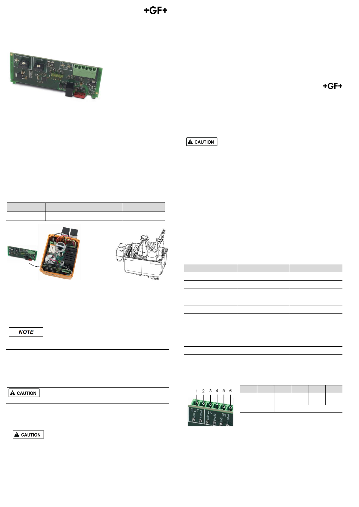
1 2 3 4 5
6
Ground
4-20
mA
Ground
0-10 V
Ground
4-20
mA
OUT
IN
GF Piping Systems
Instruction Manual
Electric actuators type EA25-250: Positioner
Georg Fischer Piping Systems Ltd CH-8201 Schaffhausen
Phone +41 (0)52 631 30 26 / info.ps@georgfischer.com / www.gfps.com
700 278 095
GFDO_6429_4 (01.16)
© Georg Fischer Piping Systems Ltd
CH-8201 Schaffhausen/Switzerland, 2016
The technical data are not binding and not expressly
warranted characteristics of the goods. They are
subject to change. Our General Conditions of Sale apply.
Using the positioner, the instruction manual of the electric
actuator type EA25-250 must be observed.
Intended use
Accessory board Positioner
The positioner can be used with the electric actuators type EA25, EA45, EA120
and EA250, both with the 24V AC/DC as well as the 100-230V AC version. The
board is to be plugged into the housing of the actuator in the provided slots.
3. Insert the board vertical on the backside of the main board onto the red plug.
4. Stick scheme label into the housing cover.
5. Set signal configuration and if necessary, motor current monitoring (see
chapter 4 „Signal configuration“ and 6 „Settings motor current monitoring“).
3 Connecting the positioner and test functioning
Connect set point 4 – 20 mA (or 0 – 10 V) to terminals of the positioner, see 5
„Terminal assignment“. Move actuator in positions OPEN and CLOSE, adjust
positions if necessary: set 4 mA (0 V) for CLOSE and 20 mA (10 V) for OPEN.
6. Put the cover back in place and fasten it with the 4 screws.
4 Signal configuration
The signal configuration is performed via the right BCD-switch „Mode“,
depending on switch position, the following signal configuration can be
achieved:
1 Function
The positioner controls a user-defined valve position proportional to a given
setpoint value. This can be 0 – 10 V or 4 – 20 mA. Feedback on the valve
position (actual value) is done via the integrated 4 – 20 mA position detection.
All signals can be inverted in any desired combination.
The monitoring card module „Motor current monitoring“ is located on the
positioner (left BCD switch). See chapter 6 „Settings motor current
monitoring“ for further settings.
2 Assembly of the positioner board
1. Remove housing cover of the electric actuator (loosen the 4 screws, open
cover).
2. Take the positioner board out of the packaging and check for damages.
5 Terminal assignment
The cables are applied as follows via a plug (according to signal configuration):
6 Settings motor current monitoring
Motor Current Monitoring
BCD
EA25
EA45
EA120
EA250
0
25
25
50
50 1 100
300
300
400 2 150
350
400
500 3 200
400
500
600 4 250
450
600
700 5 300
500
700
800 6 400
600
800
1000 7 500
700
900
1200 8 600
900
1000
1500
9 (factory setting)
700
1100
1200
1800
Error code
Description
Signal „Readyto-operate“
EA response
Setpoint error
None Actual value error
None
Setpoint reversed polarity
None
Actual value reversed
polarity
None
Setpoint short circuit
None Actual value short circuit
None
Actuator has run into
engine current limit
No
Stops
The message can be eliminated while the supply voltage is still connected
or the actuator is briefly disconnected from the mains voltage (does not
work with cycle monitoring).
The current monitoring function monitors the motor current. If the motor
current is higher than the preset value, an error is reported and the actuator
will remain in place.
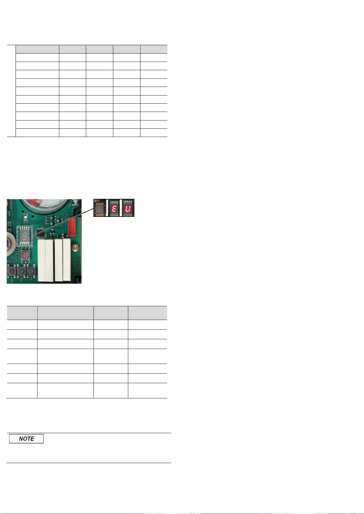
7 Error message
An error message triggers the following signals:
The 7-segment display on the main board illuminates; see illustration
below. If the positioner PCB is installed, the respective LED lights up red on
the BCD switch, if its set value is exceeded.
The ready-to-operate signal will be off (terminals 5,6 NO contact)
LED flashes yellow (except in case of power outage)
Assignment of error codes for error messages
If the positioner PCB is installed, the following error codes can be displayed:
For further error codes of the main board, see instruction manual of the electric actuator
type EA 25-250.
Acknowledge error message
Check the cause of fault, if necessary, carry out relevant maintenance.
Error can be acknowledged via the „SET“ button on the main board.
 Loading...