

Page 1

GF Piping Systems
Bedienungsanleitung
Instruction Manual
Elektrische Antriebe Typ EA25-250
Electric Actuators Type EA25-250
Page 2

Original instruction manual
Observe instruction manual
The instruction manual is part of the product and is an important element of the safety
concept.
Read and follow the instruction manual.
Always keep the instruction manual available at the product.
Pass on the instruction manual to all subsequent users of the product.
39
Page 3

Contents
Original instruction manual ...........................................................................................................39
Contents ..........................................................................................................................................40
1 Intended use .........................................................................................................................42
2 About this document ............................................................................................................42
2.1 Warnings ...............................................................................................................................42
2.2 Other related documents .....................................................................................................43
2.3 Product variants and types described .................................................................................43
2.4 Abbreviations ........................................................................................................................43
3 Safety and responsibility ......................................................................................................44
4 Transport and storage ..........................................................................................................44
5 Design and function ..............................................................................................................45
5.1 Design ...................................................................................................................................45
5.2 Identification .........................................................................................................................46
5.3 Principle of operation ...........................................................................................................46
5.3.1 Position indicator ..................................................................................................................47
5.3.2 LED status feedback.............................................................................................................48
5.3.3 Buttons for setting the end positions ..................................................................................49
5.3.4 Overload protection ..............................................................................................................50
5.3.5 Safety position .......................................................................................................................50
5.3.6 Heating element ...................................................................................................................50
5.3.7 Emergency manual override ................................................................................................50
5.4 Wiring diagram EA25/45/120/250 ........................................................................................51
5.5 Dimensional drawing of interfaces ......................................................................................52
6 Technical specifications .......................................................................................................53
7 Installation ............................................................................................................................53
7.1 Installing the actuator with valve .........................................................................................54
7.1.1 Preparation and assembly ...................................................................................................56
7.1.2 Connecting the actuator .......................................................................................................56
8 Commissioning .....................................................................................................................58
8.1 Putting the actuator into operation .....................................................................................58
9 Operation ...............................................................................................................................59
9.1 Insert the emergency manual override hand crank ...........................................................59
9.1.1 Preparation ...........................................................................................................................60
9.1.2 Procedure .............................................................................................................................60
9.2 Adjusting end positions ........................................................................................................61
40
Page 4

9.3 Inverting LED color assignment ..........................................................................................61
9.4 Adjusting the heating element .............................................................................................62
9.5 Performing a factory reset ...................................................................................................63
9.6 Teaching in the position sensor (learning run) ...................................................................63
10 Help in case of faults ............................................................................................................64
10.1 Fault message indicator.......................................................................................................64
10.2 Assignment of error codes ...................................................................................................65
10.3 Troubleshooting ....................................................................................................................66
11 Maintenance..........................................................................................................................67
12 Spare parts list .....................................................................................................................68
13 Accessories ...........................................................................................................................69
14 EC declaration of incorporation ...........................................................................................70
15 Disposal .................................................................................................................................71
41
Page 5
Intended use Operating manual
Risk of serious physical injury!
Non-observance will lead to a possible risk of fatal or serious physical injury!
Risk of minor physical injury!
Non-observance will lead to a risk of physical injury!
Risk of damage to property!
Non-observance will lead to a risk of damage to property (loss of time, loss of data, machine
damage, etc.)!
ATTENTION
1 Intended use
The electric actuators EA 25/45/120/250 are designed for assembly on a valve and for
connection to a system controller.
The electric actuators EA 25/45/120/250 are intended to activate valves with rotating
movements up to 180° (e. g. ball valves and butterfly valves).
The product is not intended for any types of use other than those described here. Nonobservance of the instructions contained in this manual will void the manufacturer's warranty
for the products mentioned above.
2 About this document
This document contains all the information necessary for installation, operation and
maintenance of the product.
2.1 Warnings
This instruction manual contains warnings that indicate a risk of death, injury, or material
damage. Always read and observe to these warnings!
42
Page 6

Operating manual About this document
Symbol
Meaning
1.
Call for action in a certain order: Here, you have to do something.
Call for action without fixed order.
Remarks: Contain especially important information for better understanding.
Abbreviation
Description
EA
Electric actuator
AC/DC
Alternating Current/Direct Current
SELV
Safety Extra Low Voltage
CW
Clockwise
CCW
Counter Clockwise
NO
Normally open contact
NC
Normally closed contact
BCD
Binary coded decimals
SMD
Surface Mounted Device
Other symbols
2.2 Other related documents
Georg Fischer industrial planning fundamentals
Assembly instructions accessories
Assembly instructions of the respective manual valve
These documents can be obtained via the agency of GF Piping Systems or under www.gfps.com.
2.3 Product variants and types described
Type EA25 24V AC/ DC and 100 – 230V AC
Type EA45 24V AC/ DC and 100 – 230V AC
Type EA120 24V AC/ DC and 100 – 230V AC
Type EA250 24V AC/ DC and 100 – 230V AC
2.4 Abbreviations
43
Page 7

Safety and responsibility Operating manual
3 Safety and responsibility
Only use the product for the intended purpose, see Intended Use.
Do not use the product if it is damaged or faulty. Sort out the product immediately or
obtain service if damaged.
Product and accessories only to be operated by persons, who have the necessary training,
knowledge or experience.
The following target groups are addressed in this instruction manual:
Operators: Operators are instructed in the operation of the actuator and observe the
safety guidelines.
Service staff: The service staff have been professionally trained and carry out
maintenance work.
Electrically qualified person: Persons who work on the electrical equipment must be
technically trained and qualified.
Regularly instruct personnel on all questions regarding the local regulations applying to
occupational safety and environmental protection, especially for pressurized pipelines.
Make sure that personnel know, understand and follow the instruction manual and the
instructions contained therein.
Observe the instruction manual for the manual valve. They are an integral component of
this manual.
Take precautions against electrostatic hazards.
4 Transport and storage
Protect the product against external forces during transport (impacts, knocks, vibrations,
etc.).
Transport and/or store the product in its unopened original packaging.
Protect the product from dust, dirt, moisture as well as heat and ultraviolet radiation.
Ensure that the product is not damaged either by mechanical or thermal influences.
Before assembly, check the product for damage during transport.
44
Page 8
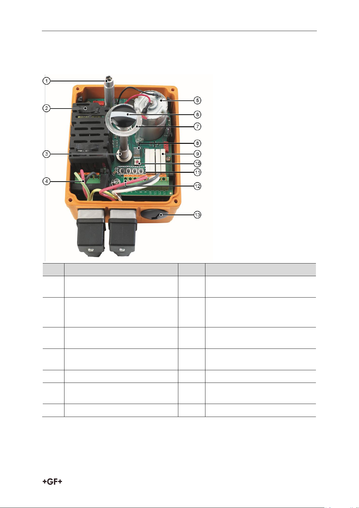
Operating manual Design and function
Item
Name
Item
Name
1
Shaft for emergency manual
override hand crank
8
7 segment error display
2
Power supply with cover (100 – 230 V
version shown)
9
Position feedback via relay for
OPEN/CLOSE/MIDDLE/ready-tooperate
3
Digital position detection
10
Heating element (temperature
threshold control)
4
Control power for
OPEN/CLOSE/MIDDLE position
11
Button for end position adjustment
5
DC motor
12
Signal output “Ready-to-operate”
6
Optical position indicator
13
Connections for DIN plug or cable
gland
7
Light tube for LED status feedback
5 Design and function
5.1 Design
45
Page 9
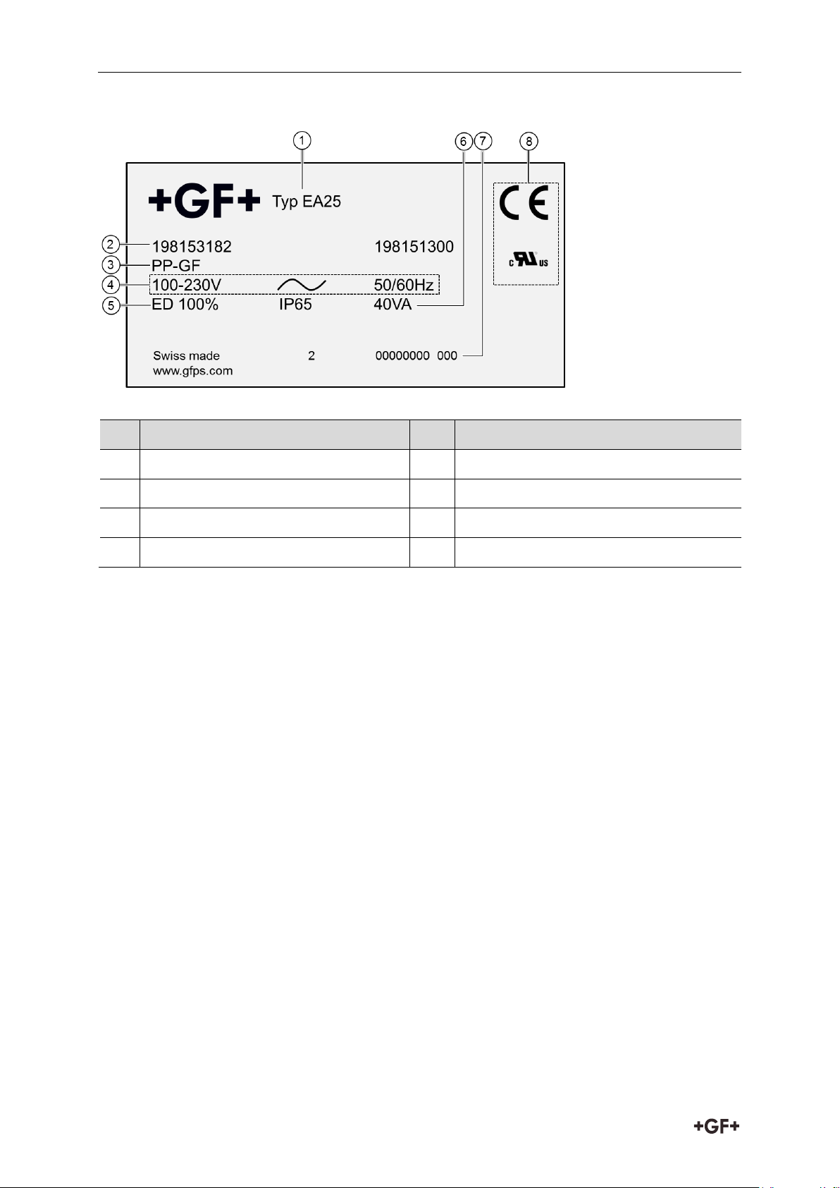
Design and function Operating manual
No.
Designation
No.
Designation
1
Type plate (e. g. EA25)
5
Duty cycle/protection rating
2
Assembly number
6
Nominal power
3
Housing material
7
Serial number
4
Voltage type
8
Approvals & CE-mark
5.2 Identification
5.3 Principle of operation
The actuator runs by switching the voltage from the OPEN position to the CLOSE position.
By switching the voltage to the other input, the actuator runs from the CLOSE position
to the OPEN position.
The end positions are factory set to 0 and 90°. Additionally, any 3rd position (MIDDLE position)
can be adjusted, which is located between the OPEN position and the CLOSE position.
This position is not assigned at the factory.
End positions and Middle position can later be changed via the end position buttons, see
Chapter 9.2 “Adjusting end positions”, Page 61.
46
Page 10
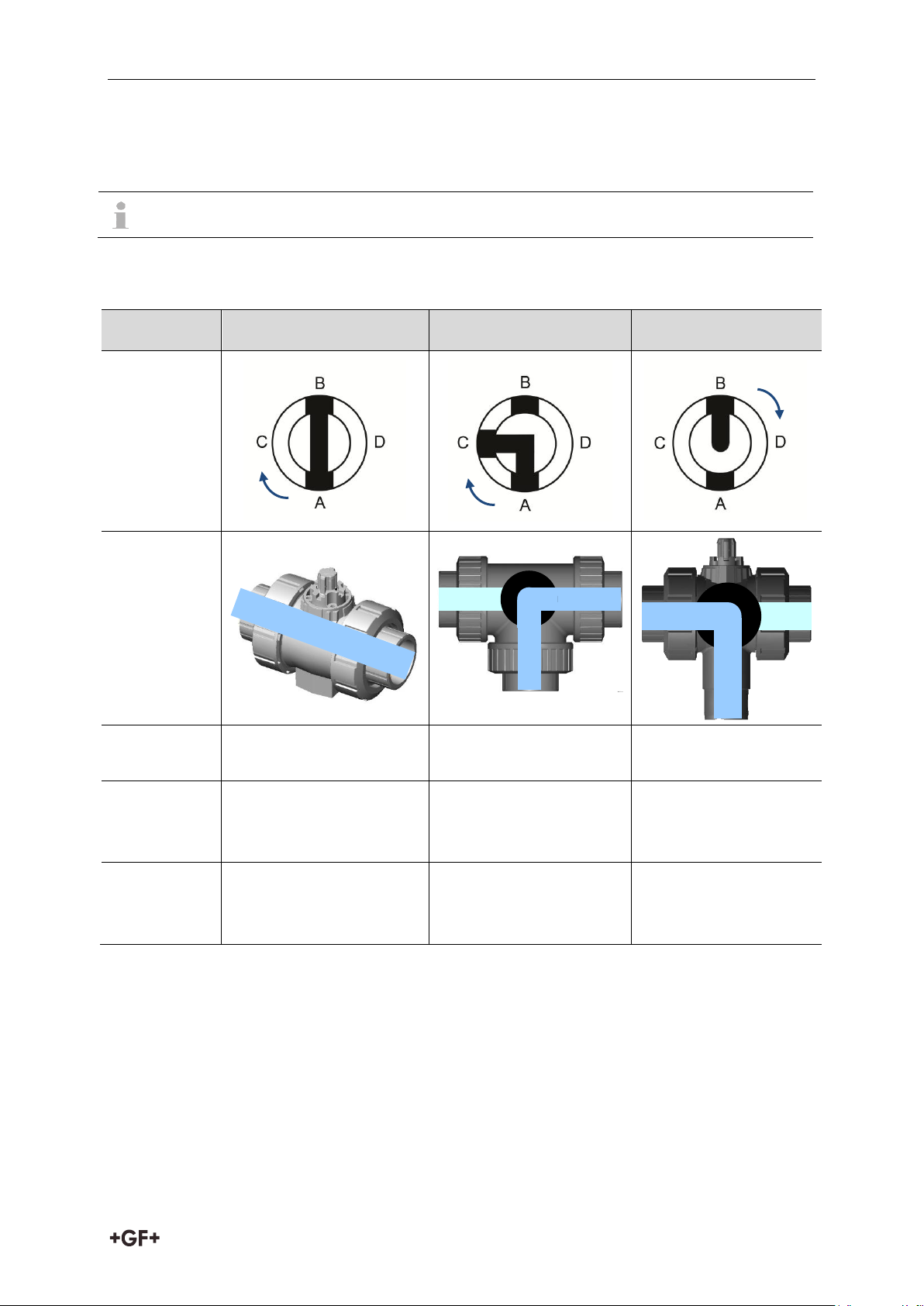
Operating manual Design and function
GF actuators are always delivered in the OPEN position.
2-way
3-way horizontal (L)
3-way vertical (L)
Image of
position
indicator
in valveposition 1
Valve
function
Actuating
angle
0° - 90°
0° - 90°
0° - 180°
Valveposition 1
A-B (OPEN)
A–C
(Flow right side, outlet
to the front)
B-C
(Flow left side, bottom
outlet)
Valveposition 2
C-D (CLOSE)
B–C
(Flow left side, outlet to
the front)
A-C
(Flow right side,
bottom outlet)
A B C D B C A
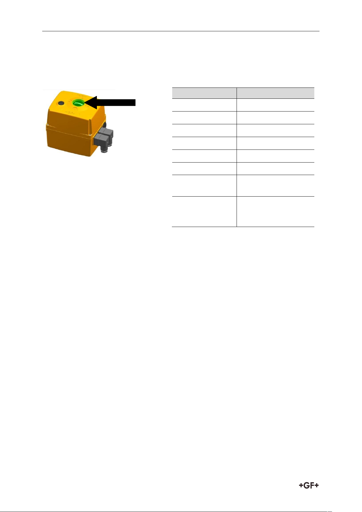
5.3.1 Position indicator
The position indicator shows the valve position. The valve positions can be read on the
installed cover.
When the cover is installed, the following image can be seen (Example ball valve):
47
Page 11
Design and function Operating manual
LED status feedback on the actuator
Color
Meaning
Red
OPEN position
Green
CLOSE position
White
MIDDLE position
Flashes white
Actuator moves
Flashes yellow
Fault
Flashes blue
Learning mode
Green/yellow
Setpoint value reached
(at positioner)
Turquoise
Adjustment run /
operation of color
inversion
5.3.2 LED status feedback
The LED status feedback shows the valve positions and the current status of the actuator.
The following table shows the color assignment of the LED:
If the plant standard requires an inversion of the color assignment, the customer can adjust
this afterwards, see Chapter 9.3 “Inverting LED color assignment”, Page 61.
48
Page 12

Operating manual Design and function
Button
Adjustment mode
(“SET” button pressed for 3 s)
Standard mode
(terminal 4
permanently
energized)
Error mode
SET
Press the button, until the color of
the LED of which the assigned
position is to be changed lights up
(e. g. green – CLOSE)
Acknowledge
the error (instead
of disconnecting
the power supply)
STORE
Saving the position moved to
Moving to
position CLOSE
CCW
Moving counterclockwise
Moving to
position MIDDLE
CW
Moving clockwise
Moving to
position OPEN
Button
combination
(press ~3s)
Function
Action
SET + CCW
LED color assignment
Inverting colors
SET + CW
Factory reset
Actuator will be set to the values
predefined at the factory
SET +
STORE
Learning run / new adjustment of
the position sensor (if magnet
position has been twisted or after
exchanging boards)
Deleting the taught in positions
5.3.3 Buttons for setting the end positions
Buttons for setting the end positions inside the actuator
The following table describes the functions of buttons shown above:
The following table describes the functions of button combinations:
49
Page 13

Design and function Operating manual
5.3.4 Overload protection
The supply unit of the EA 25/45/120/250 has an overload protection that protects the DC motor
and the power supply from overheating. The overload protection is activated as soon as the
load exceeds the torque range. The actuator motor resumes as soon as the load is in the
torque range and the temperature/current has gone down.
5.3.5 Safety position
During a power outage, the actuator remains in its current position. If the actuator is fitted
with the “fail-safe return unit” accessory, it can automatically move to a predefined safety
position (OPEN or CLOSE), in case of a power outage.
5.3.6 Heating element
The integrated heating element prevents condensation or icing inside the housing. It starts
heating from a preset value. The value depends on the ambient temperature, at which the
actuator is operated, and can be set manually. The default setting is <0 °C / <32 °F. When
the heating element is active, the dot on the 7 segment display is illuminated.
5.3.7 Emergency manual override
The integrated emergency manual override is used to run the actuator manually into another
position. The integrated emergency manual override allows the operation of the actuator to be
maintained for a short time if there is no current applied, e. g. during putting into operation or
during a power outage.
50
Page 14

Operating manual Design and function
Ex factory, the position feedback is wired as a normally closed contact (NC). On site,
this might also be implemented as a normally open contact (NO), subsequently.
Standard delivery is with a unit plug for position feedback OPEN/CLOSE. A unit plug
with additional pin for MIDDLE feedback can be ordered as an accessory or special
configuration. Each actuator is provided with this functionality. Connection via cable
gland is also possible.
5.4 Wiring diagram EA25/45/120/250
Connection of the voltage supply for positions OPEN, CLOSE and MIDDLE
Connection of position feedback for positions OPEN, CLOSE and MIDDLE (optional)
51
Page 15

Design and function Operating manual
deep
deep
deep
deep
5.5 Dimensional drawing of interfaces
EA 25/45 Flange fitting F05
EA 120 Flange fitting F07
EA 250 Flange fitting F07
52
Page 16

Operating manual Technical specifications
EA 25
EA 45
EA 120
EA 250
Nominal power
AC: 35 VA at
100 – 230 V
AC: 55 VA at
100 – 230 V
AC: 50 VA at
100 – 230 V
AC: 60 VA at
100 – 230 V
AC/DC:
40 VA at 24 V
AC/DC:
60 VA at 24 V
AC/DC:
55 VA at 24 V
AC/DC:
65 VA at 24 V
Nominal torque Mdn
(peak)
10 (25) Nm
20 (45) Nm
60 (120) Nm
100 (250) Nm
Duty cycle
100 %
50 %
50 %
35 %
Cycle time s/90°
at Mdn
5 s
6 s
15 s
20 s
Flange fitting
F05
F05
F07
F07
Tested cycles
(at 20 °C and Mdn)
250 000
100 000
100 000
75 000
Weight
2.1 kg
2.2 kg
3.6 kg
5.0 kg
Actuating angle
Max. 355°, set to 90°
Nominal voltage
AC: 100 – 230 V, 50/60 Hz
AC/DC: 24 V, 50/60 Hz
Nominal voltage
tolerance
± 15 %
Protection class
IP 65 (IP67)
1)
according to EN 60529
Pollution degree
2 according to EN 61010-1
Overload protection
Current/time dependent, resetting
Overvoltage category
II
Fuse
SMD fuse 2 A, not replaceable
Ambient
temperature
-10 °C to +50 °C
Allowable humidity
Max. 90 % relative humidity, non condensing
Housing material
PP-GF for very good chemical resistance
6 Technical specifications
1)
When used with cable glands and vertical installation
7 Installation
If a complete valve is supplied, no mounting activities and adjustments are required. The actuator
can directly be put into operation, see Chapter 8 “Commissioning” Page 58. When assembled by
the customer, the actuator must be assembled, connected, and, if necessary, adjusted.
53
Page 17

Installation Operating manual
EA 25
EA 45
EA 120
EA 250
2-way ball valve
to DN 50
e. g. ball valve
type 546
DN10-DN50 /
3/8 – 2 inch
- - -
2-way ball valve
to DN 100
e. g. ball valve
type 546
DN65-DN100 / 2
½ - 4 inch
-
-
3-way ball valve
to DN 50
e. g. ball valve
type 543
- - -
Butterfly valves
e. g. butterfly
valve type
567/578
-
7.1 Installing the actuator with valve
The actuators have a standard ISO 5211 interface, and can therefore be mounted on all valves
that are provided with this interface and the appropriate torques. The assembly using valves
from GF Piping Systems with suitable coupling piece and adapter is possible in accordance
with the following table:
54
Page 18

Operating manual Installation
Valve
2-way ball valve
3-way ball valve
Butterfly valve
Type
546
543
567
578
+
Actuator
EA
11
25 DN10 – DN50 / 3/8 – 2 inch
45 DN65 / 2 ½ inch
120 DN80 - DN100 / 3 – 4 inch
25
45 to DN65 / 2 ½
inch
120 to DN150 / 6
inch
250 from DN200 / 8
inch
= Type
107
179
180
181
182
183
184
167
168
169
170
145
146
147
Remark
metric
metric
metric
metric
ANSI
BS
JIS
horizontal
horizontal
horizontal
vertical
Wafer
Lug
Lug ANSI
Lug JIS
PVC-U
x x x x x x x x x x x
PVC-C
x x x x x x x x x x
ABS
x x x x x x x x x x
PP-H
x x x x x x x x x x
PVDF
x x x x x x x x x x
Installation and assembly of the actuator may only be carried out by electrically
qualified persons, see Chapter 3 “Safety and responsibility”, Page 44.
55
Page 19

Installation Operating manual
Voltage too high!
Danger of injury and/or damage to property.
Make sure that 24 V devices are only connected to voltages that meet the requirements
of a safety extra low voltage circuit (SELV).
Damage to the actuator by short circuit or corrosion!
Moisture and/or dirt in the actuator.
Make sure that no water enters the actuator.
Mount the cable routing, so it does not point upwards.
7.1.1 Preparation and assembly
In addition to this manual, please also follow the specifications of the valve manufacturer.
Before installation, compare the technical data of the actuator with those of the control
and the valve. Only install the actuator if the data match.
Before installation, check plugs and terminals for possible damage.
Make sure that no damaged parts are used.
Mount the actuator on the valve, see assembly instructions of the respective manual valve.
If the actuator for the system requires protection class IP67, implement the following
measures:
- Use cable glands.
- Fit the actuator vertically.
If the device is directly controlled, implement the following measures:
- Fit a circuit breaker on site.
- Do not connect earth ground conductor.
7.1.2 Connecting the actuator
Requirements
Wire gauge max. 1.5 mm²
Wire gauge min. 0.75 mm2
Sizing of the fuse: > 6 A
56
Page 20

Operating manual Installation
Premature component wear, error signals and false fail safe return signals due
to faulty control!
If the voltage is removed when reaching the end position, the status signal of the
end position is omitted and the actuator controls again the now energized position.
This causes the LED to flash red or green, as well as premature relay wear.
During normal operation avoid switching off the control power to the actuator.
E.g. connect the inputs OPEN/CLOSE as a changeover contact
Upon delivery, the heating element is set as follows:
T < 0 °C heating element is heating
T > 5 °C heating element switches off again
If required, the switch-on threshold can be set up to 40 °C.
1. Connect the unit plug for the power supply and the unit plug for position feedback
according to wiring diagram, see Chapter 5.4 “Wiring diagram EA25/45/120/250”,
Page 51. Make sure that the cable routing does not point upwards.
2. If necessary, connect the ready for operation monitoring (terminal 5.6 NO), see
Chapter 5.4 “Wiring diagram EA25/45/120/250”, Page 51.
3. If necessary, adjust the end positions, see Chapter 9.2 “Adjusting end positions”,
Page 61.
4. If necessary, adjust the heating element, see Chapter 9.4 “Adjusting the heating
element”, Page 62.
57
Page 21

Commissioning Operating manual
Using the emergency manual override hand crank, the valve can also be opened or
closed without power, see Chapter 9.1 “Insert the emergency manual override hand
crank”, Page 59.
Too high current peaks during the actuator is switched on due to charging of the mains
capacitor!
Danger of injury and/or malfunction.
Connect and operate the actuator as per wiring diagram, see Chapter 5.4 “Wiring
diagram EA25/45/120/250”, Page 51.
In case of a malfunction, the “ready-to-operate” signal goes out (normally contact)
and a fault message is indicated at the 7 segment display, see Chapter 10.1 “Fault
message indicator”, Page 64.
8 Commissioning
Before putting the system into operation, a functional test of the actuator must be carried out.
Requirements
The actuator is not connected to power.
Make sure that the supply voltage matches the details on the type plate.
Make sure that the actuator is connected properly.
Check fuse: > 6 A.
Check that the valve position matches the position indicator of the actuator.
Make sure that actuator and valve are connected correctly and tightly with each other.
8.1 Putting the actuator into operation
1. Connect the actuator to appropriate power.
The ready for operation signal appears.
2. If necessary, make further settings, e. g. invert the LED color assignment, adjust the
end positions and set the heating element, see Chapter 9 “Operation”, Page 59.
58
Page 22

Operating manual Operation
Working with removed cover on the actuator!
Danger of injury and/or damage to property.
Disconnect connections of the feed and control voltage.
Only carry out adjustments on live parts with specially insulated tools.
Direction of rotation
Function
Clockwise (CW)
close
Counter clockwise (CCW)
open
Type
Number of rotations
Angle
EA 25
9
90°
EA 45
9
90°
EA 120
27
90°
EA 250
41
90°
Unintentional restarting of the actuator!
Danger of injury due to rotation of the actuator if powered while emergency manual override
hand crank is installed.
If possible, disconnect the unit plug during manual operation or disconnect the actuator
in another way.
9 Operation
9.1 Insert the emergency manual override hand crank
The emergency manual override hand crank can be turned clockwise or counterclockwise.
The direction depends on whether the valve is to be opened or closed.
Depending on the type of actuator a different number of rotations at the crank handle is
necessary, in order to open or close the valve. The following table shows how many rotations
are necessary for the respective type:
59
Page 23

Operation Operating manual
Step 1
Step 2
Step 3
Pull the crank handle (1) out
of the holder.
Remove cover screw (2) with
crank handle (1). The magnet
centers the position. The
cover screw sticks
magnetically at the crank
handle.
Insert crank handle into the
hexagon under the opening.
Damage to the actuator by short circuit or corrosion!
Moisture and/or dirt in the actuator.
Make sure that no water has entered the actuator.
9.1.1 Preparation
9.1.2 Procedure
1. Remove power to actuator by disconnecting DIN plug.
2. Press hand crank to the stop. The crank engages.
If the actuator is still energized, the “ready-to-operate” signal will go out.
3. To open or close the valve, turn the crank handle according to the above tables.
4. In order to put the actuator back into normal operation, remove the crank handle (1).
Apply power by reinstalling DIN plug. After 3 seconds, the actuator will start up.
5. Screw on cover screw (2) again.
6. Put crank handle (1) back into the holder.
60
Page 24

Operating manual Operation
If an end position is not reached, the actuator automatically switches off after 2 min.
and displays a fault message.
Color
combination
End position
Blue/red
OPEN
Blue/green
CLOSE
Blue/white
MIDDLE
9.2 Adjusting end positions
The two end positions in the actuator have been factory set to 90°. A readjustment may be
required after assembly by the customer or after repair work.
The end positions can be set via the 4 buttons on the base board.
1. Open cover. To do so, loosen the 4 screws (torx size 20).
2. Connect the actuator to the appropriate power and let it rotate, until an end position
is reached.
3. Press the SET button and hold it for 3 seconds. The LED status feedback starts
flashing blue (adjustment mode).
4. Press the SET button again. With each pressing, the LED goes through the following
color combinations:
5. Press the SET button, until the desired color combination of the end position to be set
is displayed.
6. Move the actuator to the desired position by using the CCW and CW buttons.
7. Save the position by using the STORE button.
8. Repeat this process, until all positions are adjusted.
9. Reinstall the cover and fasten it with the 4 screws.
9.3 Inverting LED color assignment
The LED color assignment has been set at the factory to red = OPEN, and green = CLOSE.
This assignment can be inverted by the customer, if desired.
1. Open cover. To do so, loosen the 4 screws (torx size 20).
2. Make sure that the actuator is connected to appropriate power.
3. Press the SET + CCW buttons and hold them for 5 seconds.
The LED lights up turquoise. The colors red and green are inverted.
4. Reinstall the cover and fasten it with the 4 screws.
61
Page 25

Operation Operating manual
Position heating adjustment
Heating on (°C)
Heating off (°C)
0 (default)
< 0
< 5 1 5
10
2
10
15
3
15
20 4 20
25
5
25
30
6
30
35
7
35
40
8
40
45
9
40
45
When the heating element is active, the dot on the 7 segment display is illuminated.
9.4 Adjusting the heating element
Heating adjustment inside the actuator
The heating element has been set at the factory, so it starts heating from an internal device
temperature of 0 °C. For environments with higher temperatures and high humidity,
the heating threshold must be increased, in order to prevent moisture condensation inside
the housing. The heating threshold can be set via the heating adjustment.
The following table shows the positions of the heating adjustment and in which corresponding
temperature ranges the heating element will heat.
In order to change the heating threshold, turn the heating adjustment with a suitable
screwdriver to the desired position.
62
Page 26

Operating manual Operation
Damage of actuator, valve or intermediate element!
During the learning run of the position sensor, make sure that there are no structures
blocking the several 360° rotations of the actuator. If necessary, dismount the actuator
from the valve.
9.5 Performing a factory reset
When performing a factory reset, all previously saved positions will be deleted, and
a possible color inversion will be cancelled.
1. Open cover. To do so, loosen the 4 screws (torx size 20).
2. Press the SET + CW buttons.
The factory reset is performed.
9.6 Teaching in the position sensor (learning run)
1. Open the cover. To do so, loosen the 4 screws (torx size 20).
2. Press the SET + STORE buttons and hold them for 3 seconds.
The actuator does several rotations.
After completion of the learning run, the LED status feedback lights up yellow, if there
were no end positions saved before.
3. Readjusting the end positions, see Chapter 9.2 “Adjusting end positions”, Page 61.
4. Reinstall the cover and fasten it with the 4 screws.
63
Page 27

Help in case of faults Operating manual
10 Help in case of faults
10.1 Fault message indicator
7 segment display on the base board
In case of a fault message, the following events occur:
The LED flashes yellow (except during a power outage).
The “ready-to-operate” signal (terminal 5.6 NO) drops.
The 7 segment display is illuminated on the base board, see Chapter 10.2 “Assignment of
error codes”, Page 65.
If the monitoring accessories are installed, the LED on the BCD switch, of which the set
value has been exceeded, will also light up.
64
Page 28

Operating manual Help in case of faults
Error code
Description
“Ready-to-operate”
signal
EA response
No voltage
No
None
Voltage below specification
No
None
Housing internal
temperature too high (>80 °C)
No
Stops
Time from end position
to end position too long (>
120s)
No
Stops
Voltage above specification
No
Stops
Heating defective and T =
< 0 °C
No
Normal
operation
e
Error in position detection
No
None
Invalid position
No
Normal
operation
Emergency manual override
active
No
None
No communication with
accessories
No
None
Battery voltage < 50 %
(with installed fail-safe
return unit)
No
Normal
operation
Actuator was run in motor
current limit
No
Stops
10.2 Assignment of error codes
In case of a fault, the error codes will be displayed on the 7 segment display on the base board.
65
Page 29

Help in case of faults Operating manual
Repair the fault either while the supply voltage is still applied or when the actuator
is briefly disconnected from the main power (not effective in cycle monitoring).
Fault
Possible cause
Remedy
Actuator does not
react
No power available
Check voltage source.
Internal wiring error
Correct the wiring of the actuator,
see Chapter 7 “Installation”, Page 53.
End positions not correctly set
Adjust the end positions,
see Chapter 9.2 “Adjusting end
positions”, Page 61.
Motor blocked
Use emergency manual override,
see Chapter 9.1 “Insert the
emergency manual override hand
crank”, Page 59.
Actuator only
runs in one
direction
Position sensor defective
Use emergency manual override,
see Chapter 9.1 “Insert the
emergency manual override hand
crank”, Page 59.
Overload
protection is
activated
Valve dirty/jammed
Clean the valve, see valve manual.
Duty cycle too high
Extend cycle time with accessories
“Cycle time extension”.
Ambient temperature too high
If possible, reduce ambient
temperature.
Valve does not
fully close or
open
End positions not adjusted
Adjust the end positions,
see Chapter 9.2 “Adjusting end
positions”, Page 61.
Valve does not
close or open
correctly
Valve stem twisted
Replace valve stem
If an end position is not reached, the actuator automatically switches off after 2 min.
and displays a fault message.
10.3 Troubleshooting
1. Check the cause of fault. To do so, open the cover of the actuator, if necessary.
2. In order to remove the fault, press the SET button on the base board, in order
to acknowledge the error, or disconnect the actuator from the mains.
3. Perform troubleshooting in accordance with the table.
66
Page 30

Operating manual Maintenance
Lack of product quality through use of spare parts not provided by GF Piping Systems!
Danger of injury.
Only use the listed spare parts, see Chapter 12 “Spare parts list”, Page 68.
Maintenance
interval
Maintenance task
Regularly
Check that the cover of the emergency manual override is correctly
installed. If necessary, install cover.
Check that the housing cover of the actuator is secured with 4
screws.
If necessary, tighten screws.
Regularly
Check if grating noises are coming from the actuator.
Replace actuator, see assembly instructions for building valve with
actuator.
Regularly
Check that position indicator matches signal of the control.
If necessary, adjust the end positions, see Chapter 9.2 “Adjusting
end positions”, Page 61.
11 Maintenance
Set maintenance intervals as per the conditions of use (e. g. actuating cycles, fluid,
ambient temperature).
As part of the regular system inspection, carry out the following maintenance activities:
For questions regarding maintenance of the product, please contact your national GF Piping
Systems representative.
67
Page 31

Spare parts list Operating manual
Designation
Code No.
Actuator EA25 100 – 230 V AC
198 153 182
Actuator EA25 24 V AC/DC
198 153 183
Actuator EA45 100 – 230 V AC
198 153 184
Actuator EA45 24 V AC/DC
198 153 185
Actuator EA120 100 – 230 V AC
198 153 186
Actuator EA120 24 V AC/DC
198 153 187
Actuator EA250 100 – 230 V AC
198 153 188
Actuator EA250 24 V AC/DC
198 153 189
Crank for emergency manual override
198 151 307
Manual emergency cover (lock screw)
198 000 503
12 Spare parts list
68
Page 32

Operating manual Accessories
Designation
Function
Code No.
Fail-safe return unit with
integrated battery pack
In case of a power outage, the fail-safe return
unit can be used to move to a preset safe
position (OPEN/CLOSE). Assembly in the
housing actuator
199 190 601
External fail-safe return
unit
In case of a power outage, the fail-safe return
unit can be used to move to a preset safe
position (OPEN/CLOSE). Voltage supply (24 V
DC) implemented externally
199 190 604
Positioner
For continuous control operation (4-20 mA / 010 V)
199 190 603
Monitoring
For monitoring control time and motor current,
as well as for extending the control times and
counting the control cycles (even without bus
system) via a collective alarm
199 190 602
Profibus
For integrating the actuator into a Profibus DP
network
199 190 605
Diagnostic tool
For reading various data for a first error
diagnosis via USB
199 190 600
AS-Interface module
ASEV 2400
Connection to an AS-i network (supply in
combination with limit switch kit)
199 190 562
Adapter SW 11 for F04
Modification for valves with F04 interface
198 000 587
Adapter SW 14 for F05
Modification for valves with F05 interface
198 204 057
Reducer bushing WS 11
for F05
Adjustment for valves with F05 interface and
wrench size 11
198 803 145
Standard plug set
For the connection of accessories
198 000 502
Plug set 4 pin
For connection of MIDDLE position feedback
199 190 606
13 Accessories
69
Page 33

EC declaration of incorporation Operating manual
14 EC declaration of incorporation
EC Declaration of incorporation for incomplete machines (Machinery Directive 2006/42/
EC Annex II B) and EC declaration of conformity as per EMV and low voltage directive
(2004/108/EG), (2006/95/EG)
Manufacturer:
Georg Fischer Piping Systems Ltd., Ebnatstrasse 111, 8201 Schaffhausen / Switzerland
Person authorized to compile technical documentation:
Georg Fischer Piping Systems Ltd., R&D Manager, Ebnatstrasse 111, 8201 Schaffhausen /
Switzerland
We hereby confirm that the following incomplete machine
Electrical actuator
Type: EA25, EA45, EA120, EA250
Variants: 24V AC/DC, 100-230V AC
Article numbers: 198 153 182, 198 153 183, 198 153 184, 198 153 185, 198 153 186, 198 153
187, 198 153 188, 198 153 189
fulfils all the basic requirements of the machine directive 2006/42/EC, as far as the scope
of delivery allows. We further declare that the special technical documentation has been
compiled in accordance with Annex VII, Section B of this directive. We shall forward this,
if requested, to the competent authorities via the aforementioned authorized person.
Commissioning is prohibited until it has been established that the entire machine, into which
the aforementioned incomplete machine is to be incorporated, meets the provisions of
the machine directive 2006/42/EC.
The incomplete machine also meets the requirements of the following European directives,
implementing national legal provisions, and relevant harmonized standards:
Electromagnetic compatibility – Directive EMV (2004/108/EG)
Low voltage directive (2006/95/EG)
EN 15714-2 (Electrical actuators for industrial valves)
ISO 5211 (actuator interface)
EN 60068-2-6 (vibration tests)
VDE 0843 section 20 (EMV requirements)
Georg Fischer Piping Systems Ltd
Name: Antonio De Agostini
Position: R&D Manager
Georg Fischer Piping Systems Ltd
Date: 2016-01-11
70
Page 34

Operating manual Disposal
Parts of the product may be contaminated with media that are harmful to health and
the environment, so it is not enough just to clean them!
These media represent a risk of physical injury or damage to the environment.
Before disposing of the product:
Collect leaking media and dispose of them according to local regulations. Refer to
the safety data sheet.
Neutralize any media residues remaining in the product.
Separate the materials (plastics, metals etc.) and dispose of them according to local
regulations.
Products marked with this symbol must be taken to a separate collection point
for electrical and electronic devices.
If you have questions regarding the disposal of your product, please contact
your national GF Piping Systems representative.
15 Disposal
Before disposal, separate the different materials into recyclable materials, normal waste,
and special waste.
Comply with the local regulations and legislation when recycling or disposing of the
product, individual components, and packaging.
Comply with national regulations, standards and guidelines.
71
Page 35

GF Piping Systems
Worldwide at home
Our sales companies and representatives
ensure local customer support in over 100 countries
www.gfps.com
Argentina / Southern South America
Georg Fischer Central Plastics
Sudamérica S.R.L.
Buenos Aires, Argentina
Phone +54 11 4512 02 90
gfcentral.ps.ar@georgfischer.com
www.gfps.com/ar
Australia
George Fischer Pty Ltd
Riverwood NSW 2210 Australia
Phone +61 (0) 2 9502 8000
australia.ps@georgfischer.com
www.gfps.com/au
Austria
Georg Fischer
Rohrleitungssysteme GmbH
3130 Herzogenburg
Phone +43 (0) 2782 856 43-0
austria.ps@georgfischer.com
www.gfps.com/at
Belgium / Luxembourg
Georg Fischer NV/SA
1070 Bruxelles/Brüssel
Phone +32 (0) 2 556 40 20
be.ps@georgfischer.com
www.gfps.com/be
Brazil
Georg Fischer Sist. de Tub. Ltda.
04571-020 São Paulo/SP
Phone +55 (0)11 5525 1311
br.ps@georgfischer.com
www.gfps.com/br
Canada
Georg Fischer Piping Systems Ltd
Mississauga, ON L5T 2B2
Phone +1 (905) 670 8005
Fax +1 (905) 670 8513
ca.ps@georgfischer.com
www.gfps.com/ca
China
Georg Fischer Piping Systems Ltd
Shanghai 201319
Phone +86 21 3899 3899
china.ps@georgfischer.com
www.gfps.com/cn
Denmark / Iceland
Georg Fischer A/S
2630 Taastrup
Phone +45 (0) 70 22 19 75
info.dk.ps@georgfischer.com
www.gfps.com/dk
Finland
Georg Fischer AB
01510 VANTAA
Phone +358 (0) 9 586 58 25
Fax +358 (0) 9 586 58 29
info.fi.ps@georgfischer.com
www.gfps.com/fi
France
Georg Fischer SAS
95932 Roissy Charles de Gaulle Cedex
Phone +33 (0) 1 41 84 68 84
fr.ps@georgfischer.com
www.gfps.com/fr
Germany
Georg Fischer GmbH
73095 Albershausen
Phone +49 (0) 7161 302-0
info.de.ps@georgfischer.com
www.gfps.com/de
India
Georg Fischer Piping Systems Ltd
400 083 Mumbai
Phone +91 224007 2001
branchoce@georgfischer.com
www.gfps.com/in
Indonesia
George Fischer Pte Ltd –
Representative Oce
Phone +62 21 2900 8564
Fax +62 21 2900 8566
sgp.ps@georgfischer.com
www.gfps.com/sg
Italy
Georg Fischer S.p.A.
20063 Cernusco S/N (MI)
Phone +39 02 921 861
it.ps@georgfischer.com
www.gfps.com/it
Japan
Georg Fischer Ltd
556-0011 Osaka,
Phone +81 (0) 6 6635 2691
jp.ps@georgfischer.com
www.gfps.com/jp
Korea
GF Piping Systems
Georg Fischer Korea Co., Ltd.
Unit 2501, U-Tower
120 HeungdeokJungang-ro (Yeongdeok-dong)
Giheung-gu, Yongin-si, Gyeonggi-do, Korea
Phone: +82 31 8017 1450
Fax : +82 31 217 1454
kor.ps@georgfischer.com
www.gfps.com/kr
Malaysia
George Fischer (M) Sdn. Bhd.
40460 Shah Alam, Selangor Darul Ehsan
Phone +60 (0) 3 5122 5585
Fax +603 5122 5575
my.ps@georgfischer.com
www.gfps.com/my
Mexico / Northern Latin America
Georg Fischer S.A. de C.V.
Apodaca, Nuevo Leon
CP66636 Mexico
Phone +52 (81) 1340 8586
Fax +52 (81) 1522 8906
mx.ps@georgfischer.com
www.gfps.com/mx
Middle East
Georg Fischer
Piping Systems (Switzerland) Ltd
Dubai, United Arab Emirates
Phone +971 4 289 49 60
gcc.ps@georgfischer.com
www.gfps.com/int
Netherlands
Georg Fischer N.V.
8161 PA Epe
Phone +31 (0) 578 678 222
nl.ps@georgfischer.com
www.gfps.com/nl
Norway
Georg Fischer AS
1351 Rud
Phone +47 67 18 29 00
no.ps@georgfischer.com
www.gfps.com/no
Philippines
George Fischer Pte Ltd
Representative Oce
Phone +632 571 2365
Fax +632 571 2368
sgp.ps@georgfischer.com
www.gfps.com/sg
Poland
Georg Fischer Sp. z o.o.
05-090 Sekocin Nowy
Phone +48 (0) 22 31 31 0 50
poland.ps@georgfischer.com
www.gfps.com/pl
Romania
Georg Fischer
Piping Systems (Switzerland) Ltd
020257 Bucharest - Sector 2
Phone +40 (0) 21 230 53 80
ro.ps@georgfischer.com
www.gfps.com/int
Russia
Georg Fischer
Piping Systems (Switzerland) Ltd
Moscow 125040
Phone +7 495 748 11 44
ru.ps@georgfischer.com
www.gfps.com/ru
Singapore
George Fischer Pte Ltd
11 Tampines Street 92, #04-01/07
528 872 Singapore
Phone +65 6747 0611
Fax +65 6747 0577
sgp.ps@georgfischer.com
www.gfps.com/sg
Spain / Portugal
Georg Fischer S.A.
28046 Madrid
Phone +34 (0) 91 781 98 90
es.ps@georgfischer.com
www.gfps.com/es
Sweden
Georg Fischer AB
117 43 Stockholm
Phone +46 (0) 8 506 775 00
info.se.ps@georgfischer.com
www.gfps.com/se
Switzerland
Georg Fischer
Rohrleitungssysteme (Schweiz) AG
8201 Schahausen
Phone +41 (0) 52 631 30 26
ch.ps@georgfischer.com
www.gfps.com/ch
Taiwan
Georg Fischer Co., Ltd
San Chung Dist., New Taipei City
Phone +886 2 8512 2822
Fax +886 2 8512 2823
www.gfps.com/tw
United Kingdom / Ireland
George Fischer Sales Limited
Coventry, CV2 2ST
Phone +44 (0) 2476 535 535
uk.ps@georgfischer.com
www.gfps.com/uk
USA / Caribbean
Georg Fischer LLC
9271 Jeronimo Road
92618 Irvine, CA
Phone +1 714 731 88 00
Fax +1 714 731 62 01
us.ps@georgfischer.com
www.gfps.com/us
International
Georg Fischer
Piping Systems (Switzerland) Ltd
8201 Schahausen/Switzerland
Phone +41 (0) 52 631 30 03
Fax +41 (0) 52 631 28 93
info.export@georgfischer.com
www.gfps.com/int
The technical data are not binding. They neither constitute expressly
warranted characteristics nor guaranteed properties nor a guaranteed durability.
They are subject to modification. Our General Terms of Sale apply.
700.278.091
GFDO_6414_1_4 (01.16)
© Georg Fischer Piping Systems Ltd
CH-8201 Schaffhausen/Switzerland, 2016
 Loading...