

Page 1
GF Piping Systems
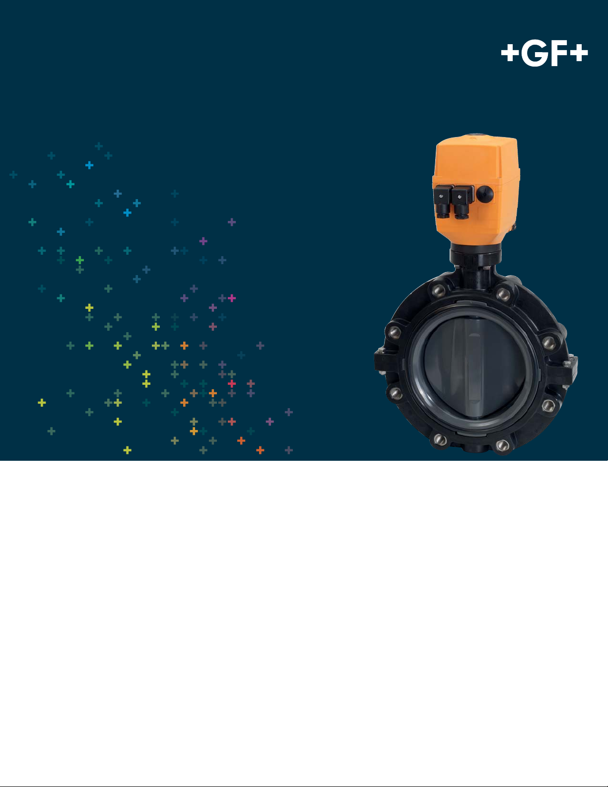
Electrically Actuated Lug Butterfly Valve
Type 147
General
• Size: 2”–12”
• Outer Body: Glass-fi lled PP
• Material: PVC, CPVC, PROGEF® Standard PP, ABS,
SYGEF®Standard PVDF
• Seals: EPDM, FPM, PTFE/FPM
• Stem: 316 stainless steel
• Voltage: 100-230VAC, 24VAC/DC
• Connection: Both ANSI 150 and DIN 2501
• Actuator Housing: Glass-fi lled PP
• Manual Override: Integrated
• End Stops: Open, close, programmable middle position
• Position Indicator: LED, optical, integrated
• Position Feedback: Open, close, middle
• Heater: 10 position adjustable
Specifi cation
The Type 145 Electrically Actuated Butterfl y Valve shall be wafer style
compatible with both ANSI B16.5 150 lb and DIN 2501 fl ange patterns.
The disk operation shall utilize double eccentric design principles.
The shaft shall be non-wetted by a bushing assembly with double
O-ring seals and fi xed at both ends. The face seal shall be a Q-ring
compatible with fl at and serrated fl ange adapters. The face, disk and
shaft seals shall operate independently. The wetted body and disk
shall be of like materials. Valves shall be rated for bidirectional use.
The operator mounting fl ange shall be comply with ISO standards. All
valves shall be tested in accordance to ISO9393 and designed to
ISO16136 standards. All valves shall be manufactured under ISO9001
for Quality and ISO14001 for Environmental Management. Following
assembly, every valve shall be tested and certifi ed bubble tight
exceeding Class VI standards.
Page 2
Material Specifi cation
s
PVC valves shall meet ASTM D1784 cell classifi cation 12454
standards. CPVC valves shall meet ASTM D1784 cell classifi cation 23447-B standards. PP valves shall meet ASTM D584714 cell classifi cation PP0510B66851 standards. ABS valves
shall meet ASTM D3965 cell classifi cation 42222 standards.
PVDF valves shall be type 1, grade 2 according to ASTM D3222
standards. Valves of all materials shall be RoHS compliant.
Key Valve Certifi cations
• NSF 61: PVC and CPVC
• FDA CFR 21 177.1520: PP and PVDF
• FDA CFR 21 177.2600: EPDM and FPM
• FDA CFR 21 177.1550: PTFE
• ABS: All materials
• USP Class VI (physiological non-toxic): EPDM, FPM, PTFE,
PP and PVDF
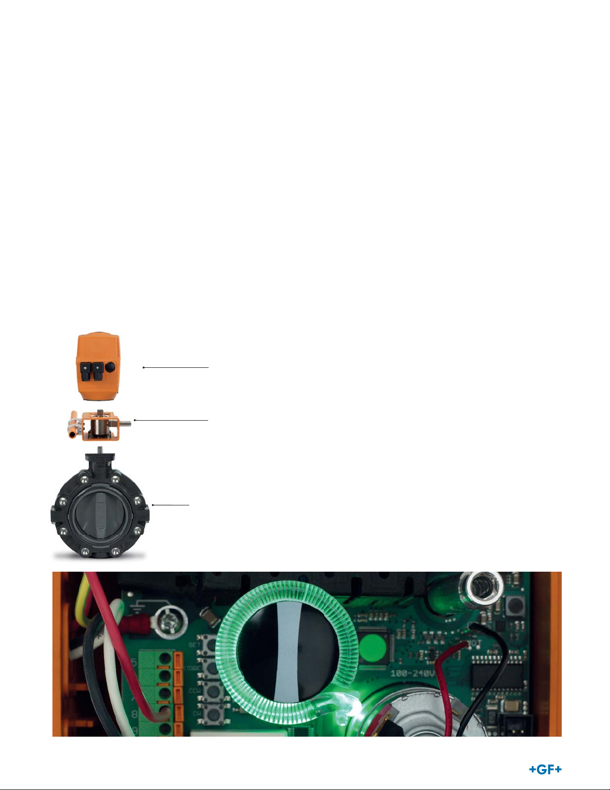
Components
omponent
Electric Actuator
Optional Features
• Positioner: Current, voltage
• Network: Profi bus DP
• Fail Safe Return: Battery back up, externally powered
board
• Smart Module: Cycle monitoring, cycle counter, cycle extension, motor current monitoring
• Manual Loading Station: Local control box
• Protection Class: IP67 with conduit connection
• Stem Extension: Two piece stainless steel
• Shaft: Titanium, Hastelloy-C
• Hardware: Alternatives available upon request
• Cleaned: Silicone free/oil free
Actuator Certifi cations/Compliance
• Machinery Directive 2006/42/EC, Annex II B
• EMV Directive CE 2004/108/CE
• EMV VDE 0843 Section 20
• Low Voltage Directive CE 2006/95/CE
• Vibration Testing EN 60068-2-6
• Interface ISO 5211
• Actuators for Inustrial Valves EN 15714-2
Intermediate Kit
Type 567 Butterfl y Valve
2
Page 3

Actuator Technical Data
EA 45 EA 120 EA 250
Valve Size 2"-2½” 3"-8” 10”-12”
Cycle Time 6s/90° 15s/90° 20s/90°
Rated Cycles at 70°F 100,000 100,000 75,000
Actuating Angle Standard set at 90°, max. 355°
Housing Material Glass-fi lled PP
Position Feedback 230V, 6 Amp
Emergency Manual Override Integrated
Rated Voltage 100- 230V, 50/60 Hz
Rated Voltage Tolerance +/- 15%
Rated Output 55VA @ 100-230VAC
Duty Cycle 50% 50% 35%
Protection Class IP 65 per EN 60529 (3)
Overload Protection Resetting, current-time dependant (1)
Overvoltage Category Category II according to DIN EN 61010-1
Power Connection Connector plug 3 P+ E per DIN EN 175301-03
Pollution Grade Grade 2 according to DIN EN 61010-1
Maximum Elevation 6561 feet
Ambient Temperature 14° to 122°F (2)
Allowable Humidity 90% relative humidity, non condensing
(1) Overload protection of the motor is dimension ed so that the motor and the power supply board are protected. As soon as the load is within the torque range, the
actuator will begin operating again.
(2) At temperatures below 14°F and if there is condensation, the heating element should be activated.
(3) Protection class IP67 for use of cable glands and vertical installation.
24V, AC/DC, 50/60Hz
60VA @ 24VAC/DC
UL/CSA: For interior use
Nema 4X
50VA @ 100-230VAC
55VA @ 24VAC/DC
60VA @ 100-230VAC
65VA @ 24VAC/DC
Technical Data
Flow
The following information is based on water applications at 68º F
Size (inch) d (mm) Cv (gal/min)
2 63 103
2½ 75 154
3 90 210
4 110 455
5 140 805
6 160 1162
8 225 2772
10 280 3570
12 315 5110
Flow CharacteristicsCv Value
100
90
80
70
60
50
40
Cv Value (%)
30
20
10
0
0 102030405060708090100
Opening Angle (%)
3
Page 4

)
Technical Data
Pressure Temperature Curves
The following graphs are based on a 25 year lifetime water or similar media application
PVC
165
150
135
120
105
90
75
60
Pressure (psi)
45
30
15
0
20 40 60 80 100 120 140 160
CPVC
165
150
135
120
105
Pressure (psi)
Temperature (°F)
PP ABS
165
150
135
120
105
90
75
60
Pressure (psi)
45
30
15
0
20 40 60 80 100 120 140 160 180
Temperature (°F)
165
150
135
120
105
Pressure (psi)
PVDF
90
75
60
45
30
15
0
20 40 60 80 100 120 140 160 180
Temperature (°F)
90
75
60
45
30
15
0
-60 -40 -20 0 20 40 60 80 100 120 140 160
Temperature (°F)
165
150
135
120
105
90
75
60
Pressure (psi)
45
30
15
0
-20 20 60 100 140 180 220 260
Temperature (°F
4
Pressure-Temperature
Material Temperature Range (ºF) Max Pressure (psi)
PVC 32 to 140 150
CPVC 32 to 176 150
PP 32 to 176 150
ABS -40 to 140 150
PVDF -4 to 284 150
Vacuum Service
The Type 147 is rated for full vacuum service. Maximum
di erential pressure of 15psi at 122ºF.
Page 5

Dimensions
The following tables are shown in inches unless otherwise specifi ed
All Materials with Manual Override
inch d2 D D1 H H1 H2 H3 H4 L L1 L2 L3 L4 Q1 Q2
2 6.3 UNC 5/8 4.75 15.71 3.03 5.28 7.4 2.36 1.77 4.8 7.09 6.5 7.87 1.57 -
2½ 7.09 UNC 5/8 5.5 16.18 3.27 5.51 7.4 2.36 1.81 4.8 7.09 7.17 7.87 2.13 1.38
3 7.68 UNC 5/8 6 16.65 3.5 5.75 7.4 2.36 1.93 4.8 7.09 8.27 7.87 2.64 1.97
4 8.9 UNC 5/8 7.5 18.15 4.17 6.57 7.4 2.36 2.2 4.8 7.09 9.45 9.84 3.46 2.91
5 10.16 UNC 3/4 8.5 19.29 4.76 7.13 7.4 2.36 2.52 4.8 7.09 10.71 9.84 4.45 3.82
6 11.18 UNC 3/4 9.5 20.08 5.24 7.44 7.4 2.36 2.83 4.8 7.09 11.81 9.84 5.47 4.84
8 13.43 UNC 3/4 11.75 22.72 6.26 8.27 8.19 2.36 2.87 4.8 7.09 14.17 9.84 7.01 6.65
5
Page 6

Dimensions
The following tables are shown in inches unless otherwise specifi ed
All Materials without Manual Override
inch d2 D D1 H H1 H2 H3 L L1 L2 L3 Q1 Q2
2 6.3 UNC 5/8 4.75 15.71 3.03 5.28 7.4 1.77 4.8 7.09 6.5 1.57 -
2½ 7.09 UNC 5/8 5.5 16.18 3.27 5.51 7.4 1.81 4.8 7.09 7.17 2.13 1.38
3 7.68 UNC 5/8 6 16.65 3.5 5.75 7.4 1.93 4.8 7.09 8.27 2.64 1.97
4 8.9 UNC 5/8 7.5 18.15 4.17 6.57 7.4 2.2 4.8 7.09 9.45 3.46 2.91
5 10.16 UNC 3/4 8.5 19.29 4.76 7.13 7.4 2.52 4.8 7.09 10.71 4.45 3.82
6 11.18 UNC 3/4 9.5 20.08 5.24 7.44 7.4 2.83 4.8 7.09 11.81 5.47 4.84
8 13.43 UNC 3/4 11.75 22.72 6.26 8.27 8.19 2.87 4.8 7.09 14.17 7.01 6.65
10 16.22 UNC 7/8 14.25 26.65 8.07 10.39 8.19 4.45 4.8 7.09 17.32 8.27 8.15
12 18.98 UNC 7/8 17 28.62 9.21 11.22 8.19 4.45 4.8 7.09 20.08 10.08 9.96
GF Piping Systems
Tel. (714) 731-8800, Toll Free (800) 854-4090, Fax (714) 731-6201
us.ps@georgfi scher.com, www.gfpiping.com
#1334-54 (2/15)
© 2015 Georg Fischer LLC
Printed in USA
 Loading...