

Page 1

GF Piping Systems
Instruction Manual
Electrical Actuator Unit Type EA 11/ 21/ 31/ 42
Page 2

Electrical actuator type EA 11
Translation of the original instructions
Disclaimer
The technical data are not binding. They neither constitute expressly warranted
characteristics nor guaranteed properties nor a guaranteed durability. They are
subject to modification. Our General Terms of Sale apply.
Observe instruction manual
The instruction manual is part of the product and an important element within the
safety concept.
Read and observe instruction manual.
Always have instruction manual available by the product.
Give instruction manual to all subsequent users of the product.
2
Page 3

Electrical actuators type EA 11/ 21/ 31/ 42 Content
Content
Content ............................................................................................................................ 3
1 Intended
2 Regarding this document......................................................................................... 4
2.1 Safety Instructions and Warnings .....................................................................
2.2 Other related documents .................................................................................. 5
2.3 Product variants and types described .............................................................. 5
3 Safety and responsibility .......................................................................................... 5
4 Transport and storage ............................................................................................. 6
5 Technical data .......................................................................................................... 7
5.1 Dimensions ............................................................
6 Design and function ................................................................................................. 11
6.1 Design EA11 ....................................................................................................... 11
6.2 Design EA21/31/42 ....................................................
6.3 Identification ...................................................................................................... 13
6.4 Position indicator .............................................................................................. 13
6.5 Operating mode on standard operation/ limit switch allocation ..................... 14
6.5.1 Overload protection .................................................................................... 14
6.5.2 Safety position ............................................................................................
7 Installation ................................................................................................................ 15
7.1 Interfaces .........................................................
7.2 Connect
7.3 Assembly actuator with valve ........................................................................... 19
7.4 Adjusting limit switches .................................................................................... 21
8 Operation .................................................................................................................. 22
8.1 Funct
8.2 Usi
8.2.1 Preparation ................................................................................................. 23
8.2.2 Procedure ...........................................................
.3 Ready to operate (only EA21 – 42) .................................................................... 24
8
8.4 Error signal ........................................................................................................ 25
8.4.1 Display fault signal ..................................................................................... 25
8.4.2 Remove fault report ................................................................................... 25
9 Maintenance ............................................................................................................. 26
10 Troubleshooting list .............................................................................................. 27
11 Spare parts list ..................................................................................................... 28
12 Accessories ........................................................................................................... 28
13 CE Declaration of incorporation ........................................................................... 31
14 Disposal ................................................................................................................. 32
use ............................................................................................................. 4
4
............................................ 9
........................................ 12
14
.................................................. 15
ion diagram EA11/ 21 /31/ 42 .............................................................. 18
ional test ................................................................................................... 22
ng manual emergency override .................................................................. 22
........................................ 23
3
Page 4
Intended use Electrical actuators type EA 11/ 21/ 31/ 42
1 Intended use
The electrical actuators EA 11/21/31/42 are intended for mounting on a valve and for
connection to a control system.
The electrical actuators EA 11/21/31/42 are intended to activate valves with pivoting
movements up to 180° (e. g. ball valves and butterfly valves).
The product is not intended for any types of use other than those described here.
Failure to follow the instructions in this manual shall lead to the termination of the
manufacturer's liability for the above mentioned products.
2 Regarding this document
This document contains all necessary information for the installation, operation and
service of the product.
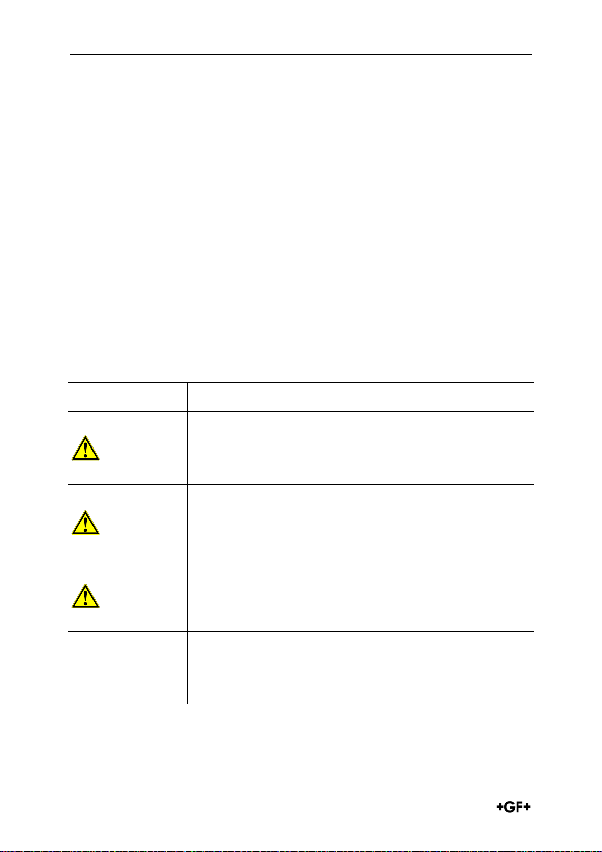
2.1 Safety Instructions and Warnings
This instruction manual contains warning notices that shall prevent you from death,
injuries or material damages. Always read and observe these warning notices!
Warning symbol Meaning
Imminent danger!
CAUTION
WARNING
WARNING
Failure to observe these warnings could result in death or very
serious injuries.
Measurements to avoid the danger.
Possible imminent danger!
Failure to observe these warnings could result in very serious
injuries.
Measurements to avoid the danger.
Dangerous situation!
Failure to observe these warnings could result in small
injuries.
Measurements to avoid the danger.
Dangerous situation!
CAUTION
4
Failure to observe these warnings could result in material
damages.
Measurements to avoid the danger.
Page 5
Electrical actuators type EA 11/ 21/ 31/ 42 Safety and responsibility
Further symbols and labels
Symbol Meaning
Notes: Especially important information.
Call for action: Here, you have to do something.
2.2 Other related documents
Document Document number
Georg Fischer planning fundamentals industry GMST 5989
Assembly instructions accessories complete GFDO 6319
These documents can be obtained from your local representative of GF Piping
Systems or at www.gfps.com
2.3 Product variants and types described
Type EA11 24V AC/ DC and 100 – 230V AC
Type EA21 24V AC/ DC and 100 – 230V AC
Type EA31 24V AC/ DC and 100 – 230V AC
Type EA42 24V AC/ DC and 100 – 230V AC
3 Safety and responsibility
Only use product as intended, see intended use.
Do not use any damaged or faulty product. Throw out any damaged product
immediately.
Product and accessories should only be operated by people who have the
necessary training, knowledge or experience.
Regularly train personnel on all locally accepted regulations on occupational
safety and environmental protection, especially on pressure-retaining pipelines.
Make sure that all personnel know, understand and follow the instruction manual
and the instructions contained therein.
Follow the instruction manual of the manual valve. It is an integral part of this
electrical actuator manual.
Take precautions against electrostatic hazards.
5
Page 6
Transport and storage Electrical actuators type EA 11/ 21/ 31/ 42
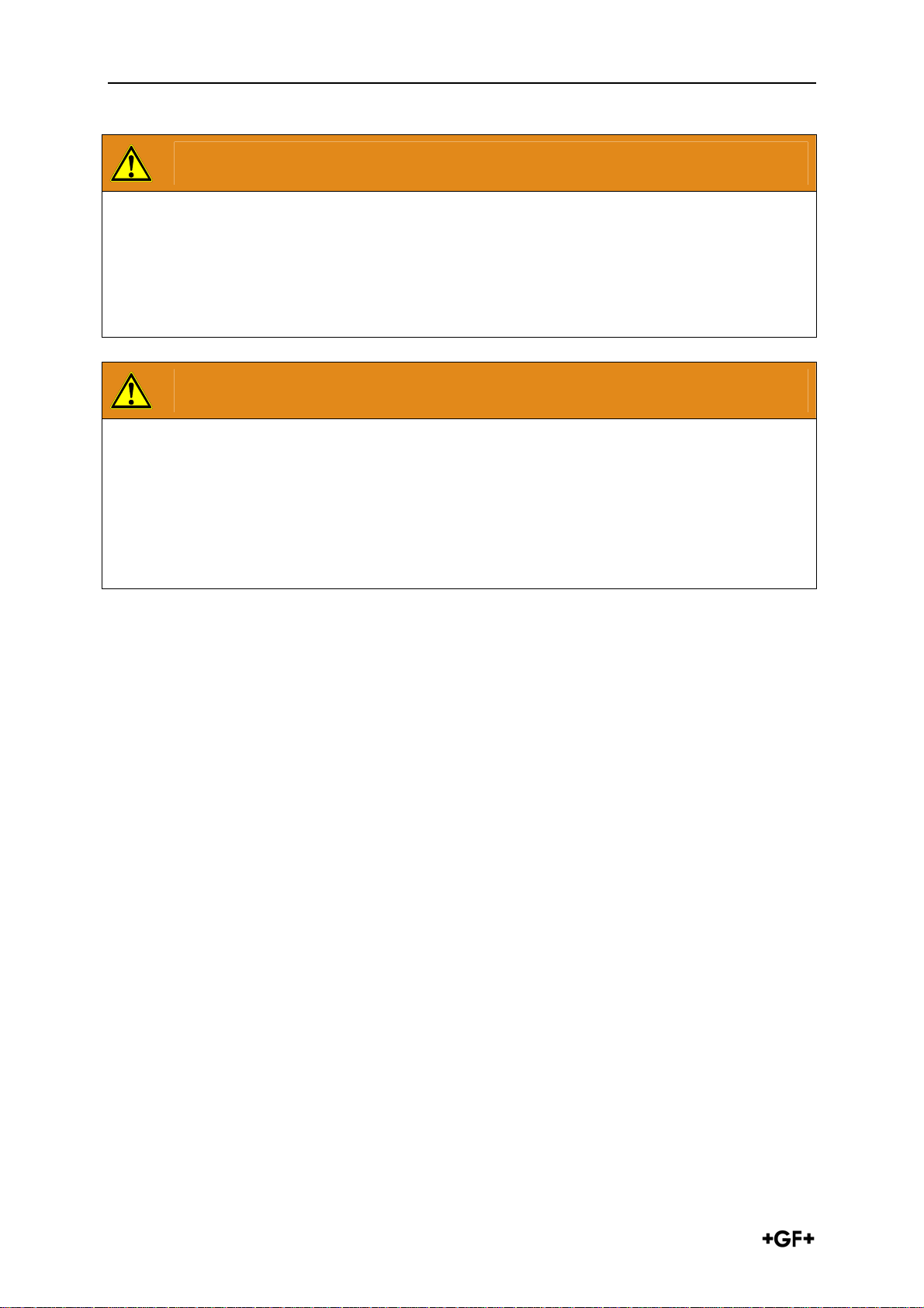
WARNING
Only work with cover removed in exceptional cases!
Danger of injury and/or damage to property.
Branch off feed and control voltage connections beforehand.
Only carry out adjustments on live parts with specially insulated tools.
WARNING
Voltage too high!
Danger of injury and/or damage to property.
Only use recommended power soures.
Make sure that 24V devices are only connected to voltages that meet the
requirements of an protective extra low-voltage circuit (SELV).
4 Transport and storage
Transport and/or store product in unopened original packaging.
Protect product from dust, heat and moisture.
Ensure that the product has not been damaged neither by mechanical nor thermal
influences.
Check product before assembly for transport damage.
6
Page 7

Electrical actuators type EA 11/ 21/ 31/ 42 Technical data
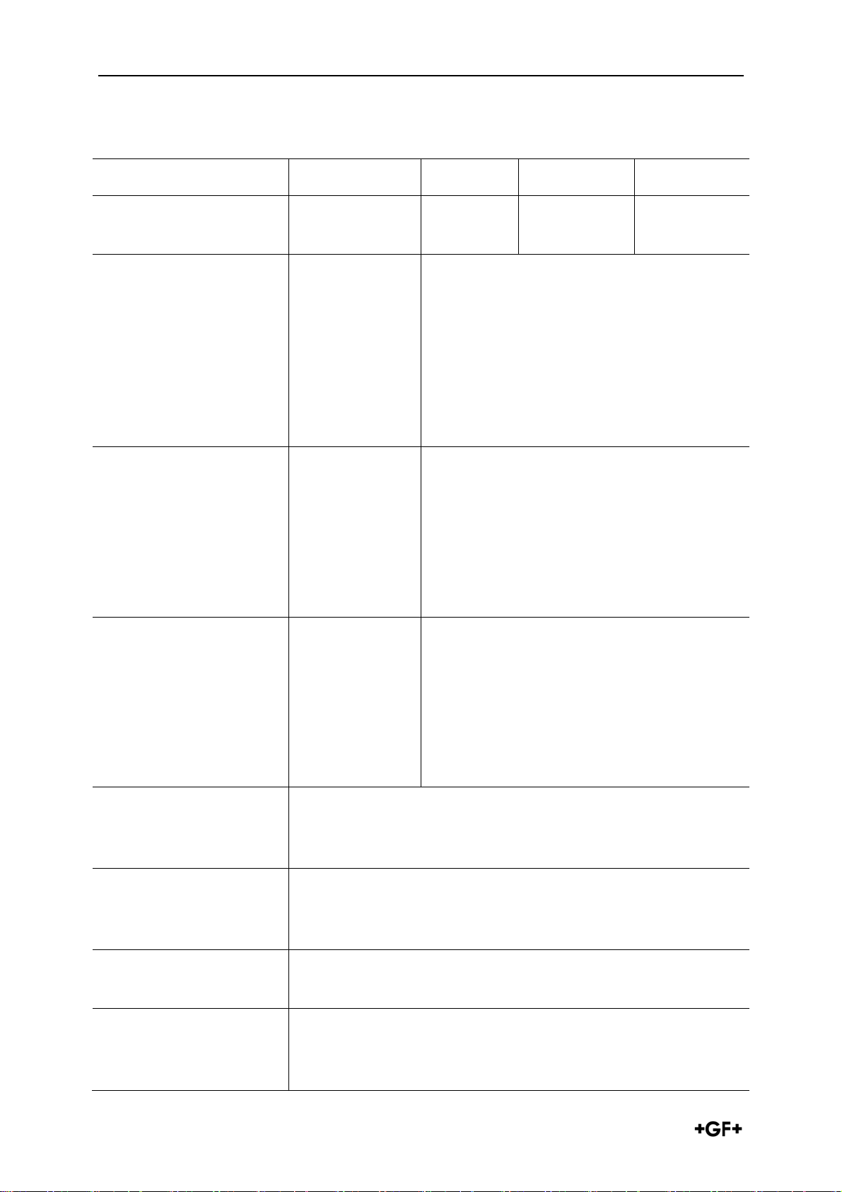
5 Technical data
EA11 EA21 EA31 EA42
Nominal torque Mdn
Peak torque
Control time
L/W/H
Flange interface/
shaft
Actuating cycles at
20°C and Mdn
Nominal output
at 24V AC/DC
at 100 – 230 V AC
Duty cycle (ED)
10 Nm 10 Nm 60 Nm 100 Nm
20 Nm 20 Nm 120 Nm 250 Nm
5 s/90° at
Mdn
129/122/138 150/122/167 150/122/190 150/122/208
F05/
Spline with
adapter
150,000 250,000 100,000 75,000
22 VA
40 VA
40% at 25°
C/15 min
5s/90° at Mdn
F05/
Spline WS11/
14
22 VA
40 VA
100%
reduced duty
cycle for UL
certification
15s/90° at
Mdn
F07/
WS17
32 VA
40 VA
50% 35%
25s/90° at
Mdn
F07/
WS22
40 VA
60 VA
Actuating angle
Housing material
Position indicator
Manual emergency
override
Rated voltage
Rated voltage
tolerance
Input impedance
max. 180°, set to 90°
PP glass fibre reinforced , flame-retardant, external rust
proof screws
optical integrated
integrated
100 – 230V, 50/60 Hz
24 = /24V, 50/60 Hz
+/- 10%
230V, 100kΩ
24V, 4.7kΩ
7
Page 8
Technical data Electrical actuators type EA 11/ 21/ 31/ 42
EA11 EA21 EA31 EA42
Weight
Ambient temperature
Electrical connection
Overload protection
1.857 kg 2.193 kg 3.536 kg 4.995 kg
-10° to + 45° C
Connector plug
3 P+E as per
EN 175301-803
(formerly DIN
43650),
additional
cable entry for
PG11
Current/timedependent
(resetting)
-10° to +
50° C
Connector plug 3 P+ E as per DIN EN
175301-803
Cable screw connection M20x1.5 as per
ISO 724
Current/time-dependent (resetting),
temperature-dependent.
The overload protection of the engine is
dimensioned in such a way that engine
and supply board are protected. As soon
as the load is in the torque range, the
actuator continues to run.
-10° to + 50° C -10° to + 50°
C
Permitted humidity
Protection class
Overvoltage category
as per DIN EN
61010-1
Height above sea level
(UL/CSA)
Degree of
contamination as per
DIN EN 61010-1
max. 80% to
31° C, reducing
in a straight
line to 50%
relative
humidity at 40°
C
IP65 as per EN60529, UL/CSA: use in internal rooms
IP67 as per EN60529: use of cable glands and vertical
assembly
II
< 2000m
2
max. 90% relative humidity, noncondensing
8
Page 9
Electrical actuators type EA 11/ 21/ 31/ 42 Technical data
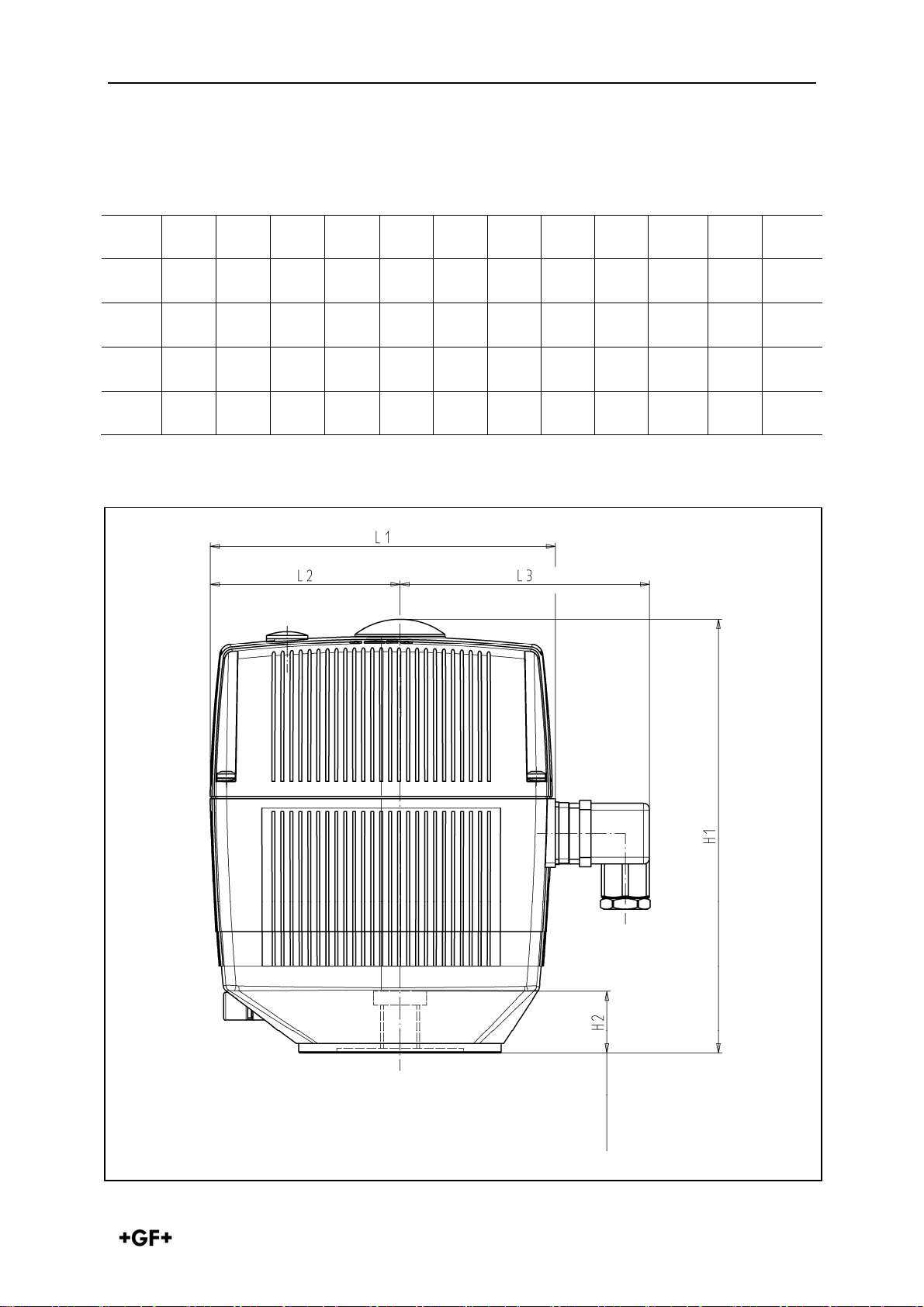
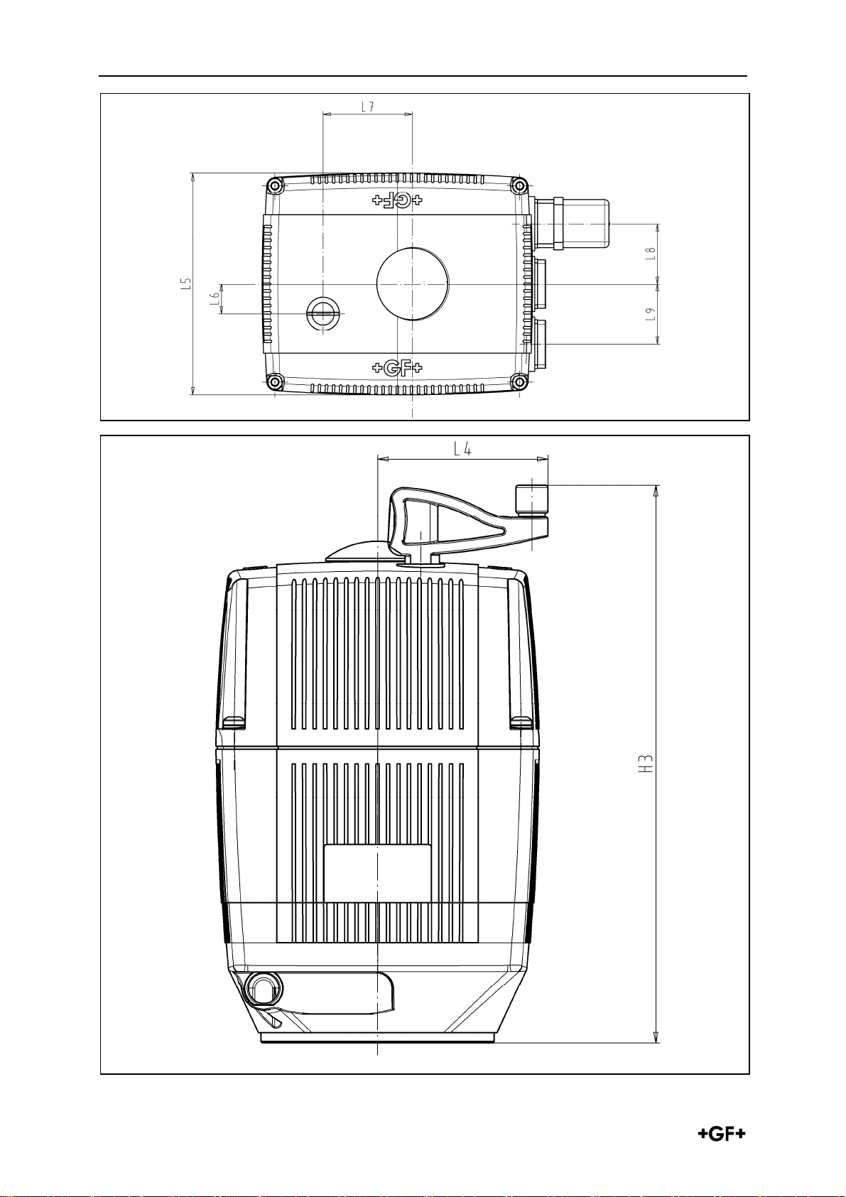
5.1 Dimensions
L1 L2 L3 L4 L5 L6 L7 L8 L9 H1 H2 H3
EA11
EA21
EA31
EA42
130 82.5 88 64.3 122 16 49 33 - 137.5 20 159.5
150 82.5 108 64.3 122 16 49 33 33 167 20 188.5
150 82.5 108 64.3 122 16 49 33 33 190 25 211.5
150 82.5 108 64.3 122 16 49 33 33 208 25 229.5
Profile depth
9
Page 10
Technical data Electrical actuators type EA 11/ 21/ 31/ 42
10
Page 11

Electrical actuators type EA 11/ 21/ 31/ 42 Design and function
6 Design and function
6.1 Design EA11
7
8
9
1
2
3
4
bb. 1
Pos. Name Pos. Name
1
2
3
4
5
For special applications, the actuator may also be fitted with accessories, see section
Accessories.
6
Direct current motor
Position indicator
Limit switches S1 and S2
Connection terminal for external
connections max. 1.5mm2
Connection option for
accessories
6
7
8
9
Wide power supply range,
without fitted contact protection
Plug X1 for accessories
Assembly bolts for accessories
Shaft for manual emergency
override
5
11
Page 12

Design and function Electrical actuators type EA 11/ 21/ 31/ 42
6.2 Design EA21/31/42
9
10
1
2
3
4
5
6
7
8
Pos. Name Pos. Name
1
2
3
4
5
For special applications, the actuator may also be fitted with accessories, see section
Accessories.
Visual position indicator
Shaft for manual emergency
override
Plug X1 for accessories
Direct current motor
Limit switches S1 and S2
6
7
8
9
10
Connection terminal for external
connections max. 1.5mm2
Modular gearbox
Connection option for accessories
Multi-voltage power supply unit,
without fitted contact protection
Assembly bolts for accessories
12
Page 13

Electrical actuators type EA 11/ 21/ 31/ 42 Design and function
6.3 Identification
Type label (e. g. EA31)
1
Order number
2
Housing material
3
Voltage type
4
5
6
7
8
Duty cycle/protection type
Nominal output
Serial number
Approvals & CE-mark
6.4 Position indicator
The position indicator displays the valve position. The valve position can be read on
the fitted cover.
GF actuators are always delivered in the "Open" position.
When the cover is fitted, the following image can be seen:
2-way
3-way horizontal
3-way vertical
Image
"Closed“ position
"Open“ position
C B – C A – C
A-B A – C B – C
13
Page 14

Design and function Electrical actuators type EA 11/ 21/ 31/ 42
6.5 Operating mode on standard operation/ limit switch allocation
The actuator moves from the "Closed" position to the "Open" position by applying live
voltage to the nominally open "S1" terminal. By applying live voltage to the normally
closed "S2" terminal, the actuator will move from the "Open" position to the "Closed"
position. Remember only to apply live voltage to one terminal at a time. The final
positions are defined by the two limit switches S1 and S2.
2
1
Switching cam that is set to limit
1
switch S1, position "Open“
Switching cam that is set to limit
2
switch S2, position "Closed“
6.5.1 Overload protection
The supply unit of the EA21/31/42 has an overload protection that protects the direct
current motor and the supply board from overheating. The overload protection is
activated as soon as the load exceeds the torque range. The actuator continues to run
as soon as the load is within the torque range and the temperature has gone down.
6.5.2 Safety position
In case of power failure, the actuator stays in its current position. If the actuator is
fitted with the accessory "fail-safe return unit“, it can automatically return to a safety
position after a power failure.
14
Page 15

Electrical actuators type EA 11/ 21/ 31/ 42 Installation
7 Installation
WARNING
Too high current peaks the first time the actuator is switched on by
charging the mains capacitor!
Danger of injury and/or malfunction.
Connect and operate actuator as per connection diagram, see Section 7.2
Connection diagram
7.1 Interfaces
EA 11/ F05
deep
deep
15
Page 16

Installation Electrical actuators type EA 11/ 21/ 31/ 42
EA 21/F05
deep
deep
EA 31/F07
deep
16
Page 17

Electrical actuators type EA 11/ 21/ 31/ 42 Installation
EA 42/F07
deep
17
Page 18

Installation Electrical actuators type EA 11/ 21/ 31/ 42
7.2 Connection diagram EA11/ 21 /31/ 42
below
Relay contact
max. 24V
EA 11
EA 21, 31, 42
18
Page 19

Electrical actuators type EA 11/ 21/ 31/ 42 Installation
7.3 Assembly actuator with valve
The electrical actuator can be assembled on the following valves with the appropriate
coupling piece and suitable adapter:
EA11 EA21 EA31 EA42
2-way ball
valve to DN
50
e. g. ball valve
type 546
DN10-DN50
2-way ball
valve to DN
100
e. g. ball valve
type 546
DN65-DN100
3-way ball
valve to DN
50
e. g. ball valve
type 543
- -
-
- -
- -
-
Butterfly
valves
e. g. butterfly
valve type
567/568
- -
19
Page 20

Installation Electrical actuators type EA 11/ 21/ 31/ 42
Valve 2-way ball valve 3-way ball valve Butterfly valve
Type 546 543 567
+
Actuator
EA
= Type
21 DN10 – DN50
11
21
31 DN65 – DN100
107 130 131 132 133 134 135 175 176 177 178 140 141 142 143
Observ
ation
metric
metric
metric
metric
ANSI
BS
JIS
horizontal
horizontal
horizontal
vertical
PVC-U
PVC-C
ABS
PP-H
x x x x x x x x x x x
x x x x x x x x x x
x x x x x x x x x x
x x x x x x x x x x
568
31 to DN150
42 of DN200
Wafer
Lug
Lug ANSI
Lug JIS
PP-N
PVDF
x x x x x x x x x x
In addition to this manual, please also follow the specifications of the valve
manufacturer.
Before assembling actuator on valve, see assembly instructions for the
intermediate parts
Before installation, compare technical data of the actuator with the control and the
valve. Only install actuator if the data matches.
Before installation, check plugs and terminals for possible damage.
Make sure that no damaged parts are used.
Have installation and assembly only carried out by specialist staff.
If actuator for system requires the protection class IP67:
- Use cable gland connections.
- Mount actuator vertically.
If device is directly controlled:
- Fit a circuit-breaker on site.
- Do not connect grounding conductor.
20
Page 21

Electrical actuators type EA 11/ 21/ 31/ 42 Installation
Requirements
- Cross section of the power lines max. 1.5 mm2.
- Fuse size: > 6 A.
Ensure that actuator is only connected to voltages that meet the requirements on
a protective extra low voltage circuit (PELV).
Connect actuator, see Section 7.2 Connection diagram
To prevent water getting into actuator, ensure that cable plug is not pointing
upwards.
If temperatures under -10°C plus water condensation are to be expected:
fit "heating element“ accessory.
7.4 Adjusting limit switches
The two end positions in the actuator have been factory set to 90°. A
readjustment may be required after assembly by the customer.
Disconnect actuator from voltage.
Open cover. To do so, loosen the 4 screws.
Position both switching cams S1 and S2 (Fig. see Section 6.5) in such a way to each
other that the angle of rotation is less than 90°.
Connect actuator to voltage and let it rotate until a limit switch is activated.
Adjust limit switch until the desired end position is set.
Repeat procedure as required until desired end positions are set.
Fit cover and fasten with the 4 screws.
21
Page 22

Operation Electrical actuators type EA 11/ 21/ 31/ 42
8 Operation
WARNING
Too high current peaks the first time the actuator is switched on by
charging the mains capacitor!
Danger of injury and/or malfunction.
Connect and operate actuator as per connection diagram, see Section 7.2
Connection diagram
Before commissioning the system, carry out a functional test of the product.
8.1 Functional test
WARNING
Working with actuator cover removed!
Danger of injury and/or damage to property.
Disconnect connections of the feed and control voltage.
Only carry out adjustments on live parts with specially insulated tools.
Before actuator is connected to mains voltage:
Make sure that main voltage matches details on type label
Make sure that actuator is connected properly
Check fuse: > 6 A
Check that valve position matches position indicator of the actuator.
Make sure that actuator and valve are connected correctly and tightly.
Using the manual emergency override, the actuator can also open or close the
valve without mains voltage, see Section 10.1
8.2 Using manual emergency override
The integrated manual emergency override is used to move the actuator manually to
another position. The integrated manual emergency override allows the actuator to
continue operating temporarily if there is no power.
if the actuator constantly or frequently fails: change actuator.
22
Page 23

Electrical actuators type EA 11/ 21/ 31/ 42 Operation
8.2.1 Preparation
Remove crank handle 1 from the holder.
Remove cover screw 2 with crank handle 1.
Insert crank handle in hexagonal bolt under the opening.
8.2.2 Procedure
WARNING
Actuator unintentionally restarting!
Danger of injury due to opening or closing of the valve through connection
terminals powered on again.
Remove connector plug during manual operation.
Disconnect actuator elsewhere.
Press crank handle as far as it will go.
Micro-switch that disconnects the actuator is activated.
To power the actuator on again: let crank handle go.
To open or to close valve: turn crank handle.
Direction of rotation Function
Clockwise (CW) close
Counter clockwise (CCW) open
Type Number of rotations Angle
EA11 9 90°
EA21 9 90°
EA31 27 90°
EA42 41 90°
23
Page 24

Operation Electrical actuators type EA 11/ 21/ 31/ 42
WARNING
Damage to the actuator by short circuit or corrosion!
Moisture and/or dirt in the actuator.
Make sure that no water has got into the actuator.
Screw cover screw 2 after using the manual emergency override back
into the actuator.
Take crank handle 1 away.
Screw cover screw 2 on again. Beforehand make sure that no water has entered
the actuator.
Put crank handle 1 back into holder.
8.3 Ready to operate (only EA21 – 42)
The EA 21/ 31/ 42 has a temperature monitor (ready for operation monitor).
Make sure that actuator is properly connected, see section 7.2 Connection
diagram.
24
Page 25

Electrical actuators type EA 11/ 21/ 31/ 42 Operation
8.4 Error signal
8.4.1 Display fault signal
In the case of a fault report
- the red LED 8 on the main board lights up. If the monitoring print is installed,
the particular LED lights up red on the BCD switch 10, if its set value is
exceeded.
- the ready to operate signal does not apply (terminal 5,6 no passage).
8.4.2 Remove fault report
Check cause of fault
If necessary, carry out relevant maintenance, see Section 10 fault repair
Repair the fault either while the supply voltage is still connected or while the
actuator is briefly disconnected from the mains voltage. (Not effective in cycle
monitoring).
To repair, activate the reset switch 9 on motherboard.
25
Page 26

Maintenance Electrical actuators type EA 11/ 21/ 31/ 42
9 Maintenance
WARNING
Defective product quality through use of spare parts, not provided by GF
Piping Systems!
Danger of injury.
Only use the listed spare parts, see section Spare parts list.
Set maintenance intervals as per the conditions of use (e. g. actuating cycles,
medium, ambient temperature).
As part of the regular system inspection, carry out the following maintenance
activities.
Maintenance interval Maintenance activity
Check that cover of the manual emergency override is
correctly fitted. If necessary, fit cover.
regular
regular
regular
For questions regarding the maintenance of the product, please contact your
GF Piping Systems representative.
Check that housing cover of the actuator is fitted with
4 screws.
If necessary, complete screws.
Check if grating noises are coming from the actuator.
Replace actuator, see assembly instructions on the
structure valve with actuator
Check that position display matches signal of the
control.
If necessary, adjust limit switch, see Section adjust
limit switches.
26
Page 27

Electrical actuators type EA 11/ 21/ 31/ 42 Troubleshooting list
10 Troubleshooting list
Problem Possible cause Solution
No mains voltage available. Check voltage source.
Actuator does not
react
Actuator only runs in
one direction
Overload protection is
activated
Valve closes or does
not open fully
Internal wiring fault
Switching cams S1 and S2 set
wrong
Motor locked
Limit switch faulty
Valve is dirty
Duty cycle too high
Too high ambient temperature
Switching cam S1 and/or S2
not adjusted
Correct wiring of the
actuator, see Section 7
Adjust limit switch, see
Section 7.2
Use manual emergency
override, see Section 10.1
Use manual emergency
override, see Section 10.1
Clean valve, see manual on
the valve
Extend cycle time with
accessories "Actuating cycle
extension“
If possible, reduce ambient
temperature
Adjust limit switch, see
Section 7.2
Valve stem twisted Replace valve stem
If an end position is not reached, the actuator switches off automatically after
2 minutes and displays a fault report.
7
2
Page 28

Spare parts list Electrical actuators type EA 11/ 21/ 31/ 42
11 Spare parts list
Name Code
Actuator EA11 100–230 V~ 198 150 180
Actuator EA11 24 AC/DC 198 150 181
Actuator EA21 100–230 V~ 198 150 182
Actuator EA21 24 V=/~ 198 150 183
Actuator EA31 100–230 V~ 198 150 184
Actuator EA31 24 V=/~ 198 150 185
Actuator EA42 100–230 V~ 198 150 186
Actuator EA42 24 V=/~ 198 150 187
Manual emergency key 198 151 307
Manual emergency cover (lock screw) 198 000 503
12 Accessories
Name Function Code EA11 EA21-42
In a power cut, the
Fail-safe return unit
Heating element
Battery set 198 151 317 x x
Kit 2 additional* limit
switches AgNi
Kit 2 additional* limit
switches Au
Kit 2 additional limit
switches NPN
fail-safe return unit
can be used to control
a preset safe position.
Prevents formation of
condensate in the
actuator
Position feedback for
the actuator with two
mechanical limit
switches
199 190 085 x x
199 190 086 x x
199 190 092 x x
199 190 093 x
199 190 096 x
28
Page 29

Electrical actuators type EA 11/ 21/ 31/ 42 Accessories
Name Function Code EA11 EA21-42
Kit 2 additional limit
switches PNP
Assembly set 4 limit
switches
Middle position 199 190 094 x
Monitoring print 199 190 079 x
Position detection 199 190 084 x
Positioner type PE25 199 190 100 x
Test adapter kit for
RS232 interface
Connection to an AS-i
AS Interface module
ASEV 2400
network (supply in
combination with limit
switch kit)
199 190 095 x
199 190 097 x
198 151 426 x
199 190 562 x x
Set of plugs
Adapter SW 14 for F05
Adapter SW 11 for F04
Reducing bush WS11
for F05
Heating element and
fail-safe return unit
For the connection of
accessories
Modification for valves
with F05 interface
Modification for valves
with F04 interface
Adjustment for valves
with F05 interface and
width across flat 11
Combined board of
heating element and
fail-safe return unit
198 000 502 x x
198 204 057 x EA21
198 000 587 x EA21
198 803 145
x EA21
199 190 087 x x
9
2
Page 30

CE Declaration of incorporation Electrical actuators type EA 11/ 21/ 31/ 42
13 CE Declaration of incorporation
CE declaration of incorporation for incomplete machines (Machinery directive
2006/42/EC, Annex II B) and CE declaration of conformity as per EMV- and low
voltage directive (2004/108/CE), (2006/95/CE)
Manufacturer:
Georg Fischer Piping Systems Ltd., Ebnatstrasse 111, 8201 Schaffhausen /
Switzerland
Person authorised to compile technical documentation:
Georg Fischer Piping Systems Ltd., R&D Manager,
Ebnatstrasse 111, 8201 Schaffhausen / Switzerland
We hereby confirm that the following incomplete machine
Electrical actuator
Type: EA11, EA21, EA31, EA42
Variants: 24V AC/DC, 100-230V AC
Article numbers: 198 150 180, 198 150 181, 198 150 182, 198 150 183, 198 150 184,
198 150 185, 198 150 186, 198 150 187
fulfils all the basic requirements of the machine directive 2006/42/EC, as far as the
scope of delivery allows.
We further declare that the special technical documentation has been compiled in
accordance with Annex VII, Section B of this directive. We shall forward this, if
requested, to the competent authorities via the aforementioned authorised person.
Commissioning is prohibited until it has been established that the entire machine,
into which the aforementioned incomplete machine is to be incorporated, meets the
provisions of the machine directive 2006/42/EC.
The incomplete machine also meets the requirements of the following European
directives and the national legal provisions implementing them and the relevant
harmonised standards below:
Electromagnetic compatibility – Directive EMV (2004/108/CE)
Low voltage directive (2006/95/CE)
EN 15714-2 (Electrical actuators for industrial valves)
ISO 5211 (actuator interface)
EN 60068-2-6 (vibration tests)
VDE 0843 section 20 (EMV requirements)
Name: Antonio De Agostini
Position: R&D Manager
Georg Fischer Piping Systems
Date: 2013-08-09
30
Page 31

GF Piping Systems
Worldwide at home
Our sales companies and representatives
ensure local customer support in over 100 countries
www.gfps.com
Argentina / Southern South America
Georg Fischer Central Plastics
Sudamérica S.R.L.
Buenos Aires, Argentina
Phone +54 11 4512 02 90
gfcentral.ps.ar@georgfischer.com
www.gfps.com/ar
Australia
George Fischer Pty Ltd
Riverwood NSW 2210 Australia
Phone +61 (0) 2 9502 8000
australia.ps@georgfischer.com
www.gfps.com/au
Austria
Georg Fischer
Rohrleitungssysteme GmbH
3130 Herzogenburg
Phone +43 (0) 2782 856 43-0
austria.ps@georgfischer.com
www.gfps.com/at
Belgium / Luxembourg
Georg Fischer NV/SA
1070 Bruxelles/Brüssel
Phone +32 (0) 2 556 40 20
be.ps@georgfischer.com
www.gfps.com/be
Brazil
Georg Fischer Sist. de Tub. Ltda.
04795-100 São Paulo
Phone +55 (0) 11 5525 1311
br.ps@georgfischer.com
www.gfps.com/br
Canada
Georg Fischer Piping Systems Ltd
Mississauga, ON L5T 2B2
Phone +1 (905) 670 8005
Fax +1 (905) 670 8513
ca.ps@georgfischer.com
www.gfps.com/ca
China
Georg Fischer Piping Systems Ltd
Shanghai 201319
Phone +86 21 3899 3899
china.ps@georgfischer.com
www.gfps.com/cn
Denmark / Iceland
Georg Fischer A/S
2630 Taastrup
Phone +45 (0) 70 22 19 75
info.dk.ps@georgfischer.com
www.gfps.com/dk
Finland
Georg Fischer AB
01510 VANTAA
Phone +358 (0) 9 586 58 25
Fax +358 (0) 9 586 58 29
info.fi.ps@georgfischer.com
www.gfps.com/fi
France
Georg Fischer SAS
95932 Roissy Charles de Gaulle Cedex
Phone +33 (0) 1 41 84 68 84
fr.ps@georgfischer.com
www.gfps.com/fr
Germany
Georg Fischer GmbH
73095 Albershausen
Phone +49 (0) 7161 302-0
info.de.ps@georgfischer.com
www.gfps.com/de
India
Georg Fischer Piping Systems Ltd
400 076 Mumbai
Phone +91 224007 2001
branchoffice@georgfischer.com
www.gfps.com/in
Italy
Georg Fischer S.p.A.
20063 Cernusco S/N (MI)
Phone +39 02 921 861
it.ps@georgfischer.com
www.gfps.com/it
Japan
Georg Fischer Ltd
556-0011 Osaka,
Phone +81 (0) 6 6635 2691
jp.ps@georgfischer.com
www.gfps.com/jp
Korea
Georg Fischer Piping Systems
271-3 Seohyeon-dong Bundang-gu
Seongnam-si, Gyeonggi-do
Seoul 463-824
Phone +82 31 8017 1450
Fax +82 31 8017 1454
kor.ps@georgfischer.com
www.gfps.com/kr
Malaysia
George Fischer (M) Sdn. Bhd.
40460 Shah Alam, Selangor Darul Ehsan
Phone +60 (0) 3 5122 5585
my.ps@georgfischer.com
www.gfps.com/my
Mexico / Northern Latin America
Georg Fischer S.A. de C.V.
Apodaca, Nuevo Leon
CP66636 Mexico
Phone +52 (81) 1340 8586
Fax +52 (81) 1522 8906
mx.ps@georgfischer.com
www.gfps.com/mx
Middle East
Georg Fischer
Piping Systems (Switzerland) Ltd
Dubai, United Arab Emirates
Phone +971 4 289 49 60
gcc.ps@georgfischer.com
www.gfps.com/int
Netherlands
Georg Fischer N.V.
8161 PA Epe
Phone +31 (0) 578 678 222
nl.ps@georgfischer.com
www.gfps.com/nl
New Zealand
Georg Fischer Ltd
13 Jupiter Grove, Upper Hutt 5018
PO Box 40399, Upper Hutt 5140
Phone +64 (0) 4 527 9813
nz.ps@georgfischer.com
www.gfps.com/nz
Norway
Georg Fischer AS
1351 Rud
Phone +47 67 18 29 00
no.ps@georgfischer.com
www.gfps.com/no
Poland
Georg Fischer Sp. z o.o.
05-090 Sekocin Nowy
Phone +48 (0) 22 31 31 0 50
poland.ps@georgfischer.com
www.gfps.com/pl
Romania
Georg Fischer
Piping Systems (Switzerland) Ltd
020257 Bucharest - Sector 2
Phone +40 (0) 21 230 53 80
ro.ps@georgfischer.com
www.gfps.com/int
Russia
Georg Fischer
Piping Systems (Switzerland) Ltd
Moscow 125047
Phone +7 495 258 60 80
ru.ps@georgfischer.com
www.gfps.com/ru
Singapore
George Fischer Pte Ltd
11 Tampines Street 92, #04-01/07
528 872 Singapore
Phone +65 6747 0611
sgp.ps@georgfischer.com
www.gfps.com/sg
Spain / Portugal
Georg Fischer S.A.
28046 Madrid
Phone +34 (0) 91 781 98 90
es.ps@georgfischer.com
www.gfps.com/es
Sweden
Georg Fischer AB
117 43 Stockholm
Phone +46 (0) 8 506 775 00
info.se.ps@georgfischer.com
www.gfps.com/se
Switzerland
Georg Fischer
Rohrleitungssysteme (Schweiz) AG
8201 Schaffhausen
Phone +41 (0) 52 631 30 26
ch.ps@georgfischer.com
www.gfps.com/ch
Taiwan
Georg Fischer Co., Ltd
San Chung Dist., New Taipei City
Phone +886 2 8512 2822
Fax +886 2 8512 2823
www.gfps.com/tw
United Kingdom / Ireland
George Fischer Sales Limited
Coventry, CV2 2ST
Phone +44 (0) 2476 535 535
uk.ps@georgfischer.com
www.gfps.com/uk
USA / Caribbean
Georg Fischer LLC
Tustin, CA 92780-7258
Phone +1 (714) 731 88 00
Toll Free 800 854 40 90
us.ps@georgfischer.com
www.gfpiping.com
Vietnam
George Fischer Pte Ltd
136E Tran Vu, Ba Dinh District, Hanoi
Phone +84 4 3715 3290
Fax +84 4 3715 3285
International
Georg Fischer
Piping Systems (Switzerland) Ltd
8201 Schaffhausen/Switzerland
Phone +41 (0) 52 631 30 03
Fax +41 (0) 52 631 28 93
info.export@georgfischer.com
www.gfps.com/int
The technical data are not binding. They neither constitute expressly
warranted characteristics nor guaranteed properties nor a guaranteed durability.
They are subject to modification. Our General Terms of Sale apply.
700.278.082
GFDO_6323_1_2_4_6 (08.13)
© Georg Fischer Piping Systems Ltd
CH-8201 Schaffhausen/Switzerland, 2013
Printed in Switzerland
 Loading...