

Page 1

Elektrischer Stellantrieb
Typ EA 21/31/42
Bedienungsanleitung
Electrical Actuator Unit
Type EA 21/31/42
Instruction Manual
Page 2

English
Index of content
1. Introduction ..................................................................36
General Information ...................................................................... 36
2. EC Manufacturer’s Declaration ..................................36
3. Intended use .................................................................37
4. Safety Information .......................................................37
4.1 Due care required by the operator ......................................... 37
4.2 Special hazards ........................................................................ 37
4.3 Transport and Storage ............................................................ 38
5. Actuator Design ............................................................38
5.1 Wiring Diagram for Standard Version .................................... 39
5.2 Error message ......................................................................... 39
5.3 DIP switch in case of error ...................................................... 40
6. Setting Up the Actuator ............................................... 40
6.1 Emergency Manual Override ...................................................41
6.2 Dimensional drawings of the
Electrical Actuator Type E A 21/31 ............................................. 42
6.3 Technical Specications ..........................................................43
7. Mounting and Connecting Supplementary Kits ...........44
7.1 Heating Element ....................................................................... 44
7.2 Fail-safe return ........................................................................ 45
7.3 Additional Limit Switches ........................................................ 47
7.3.1 Additional 4 Limit Switches ........................................... 48
7.4 Middle Positioning .................................................................... 49
7.5 Monitoring print ........................................................................ 52
7.6 Position Signalization .............................................................. 58
7.7 Positioner .................................................................................. 60
8. TROUBLESHOOTING ....................................................66
Ordering Information ....................................................... 67
Notizen/Notice/Note ............................................................................ 68
37
Page 3
Warning
Beantragt/pending
symbols
Danger
Hazard
1. Introduction
This instruction manual contains all the pertinent information on the design, installation and operation of the electrical actuator type EA 21/31/42.
General Information
Hazard notices
Hazard notices are used in this manual to warn you of possible injuries or
damages to proper ty. Please read and follow these hazard notices at all
times!
Meaning
Imminent acute danger!
Failure to comply could result in death or extremely serious injury.
Possible acute danger!
Failure to comply could result in serious injury.
Dangerous situation!
Failure to comply could lead to injur y or damage to proper ty.
Caution
38
2. EC Manufacturer’s Declaration
The manufacturer, Georg Fischer Piping Systems Ltd., CH 8201 Schaffhausen, declares that the electrical actuator EA 21 / 31 / 42 is not a ready-to-
use machine in the sense of the EC Machine Directive and therefore cannot
meet all the requirements of this directive.
Operation of these actuators is prohibited until conformity of the entire
system into which the valve and the actuator have been installed is established according to the EC Directives listed below.
Applied EC Directives:
06/95 EC EC Low Voltage Directive
89/336 EEC EC Directive on Electromagnetic
Compatibility
Page 4
Modications to the actuator which have an effect on the technical data
given in this instruction manual and its intended use, i.e. signicantly alter
the actuator, render this manufacturer’s declaration null and void.
3. Intended use
When mounted on a valve and connected to a system control and provided
that the actuator data corresponds to the electrical control and the valve,
the purpose of this actuator is:
• to actuate valves with up to 180° pivoting (ball valves and buttery
valves),
• to indicate the previously calibrated end positions of the valve via electrical signal to the system control (accessory), and
• in case of a power supply interruption the actuator valve remains in its
current position (without accessory). Please use emergency manual
override or install fail-safe return.
The actuator is not intended for uses other than those listed above. If the
instructions contained in this manual are not observed, the manufacturer is
excluded from all liability for the above mentioned products.
4. Safety Information
4.1 Due care required by the operator
The actuator described herein was designed and manufactured with consideration to the respective harmonized European standards. It corresponds
to the latest technology and the technical specications contained under
section 6.3.
Safety on the job can, however, only be realized if the operator warrants that
• the actuator is only used as indicated under section 3,
• he is familiar with this instruction manual and the manual of the corresponding valve and adheres to the instructions contained therein and
• he has taken the necessary measures against electrostatic inuence.
4.2 Special hazards
Under normal conditions, the actuator may only be operated with the
cover closed.
If work is performed on the actuator with the cover removed, the supply
and control voltage must rst be disconnected. Adjustments, which need
to be done in the energized state, should be carried out with special insulated tools.
39
Page 5
In addition, the operating instructions of the manual valve
must be observed. They are an integral component of this
manual.
4.3 Transport and Storage
The actuators must be handled, transported
and stored with care. Please note the following
points:
• The actuators should be transported and/or stored in
their original unopened packaging.
• The actuators must be protected from harmful physical
inuences such as dust, heat (humidity).
• It is important that the connections are neither damaged by mechanical nor by thermal inuences.
• Prior to installation, the actuators should be inspected
for transport damages. Damaged actuators must not be
installed.
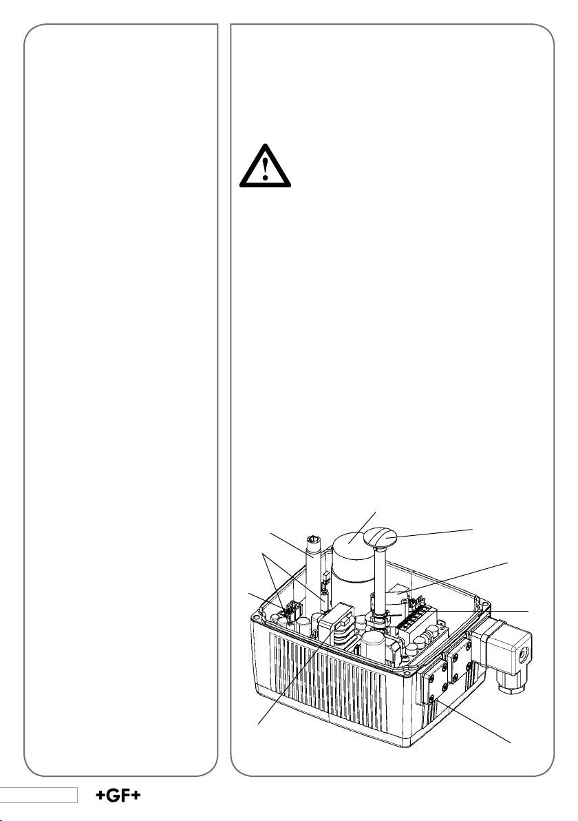
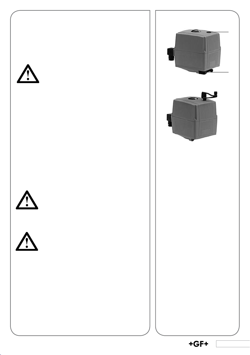
5. Actuator Design
The standard version of the EA 21/31/42 electrical actuator
consists of the following elements: gear unit, direct current
motor, electrical board and components for end position
limiting.
1. Limit switches S1 and S2
2. Direct current motor
3. Optical position indicator
4. Plug X1 for accessories
5. Terminal strip for external
connections max. 1.5 mm
6. Wide range power supply,
without protection against
accidental contact
7. Shaft for emergency manual
override
8. Connections for DIN plug or
cable gland
9. Assembly bolts for accessories
40
For special applications, the actuator can be equipped additionally with various supplementary kits (see section 7).
2
7
9
2
4
6
3
1
5
8
Page 6
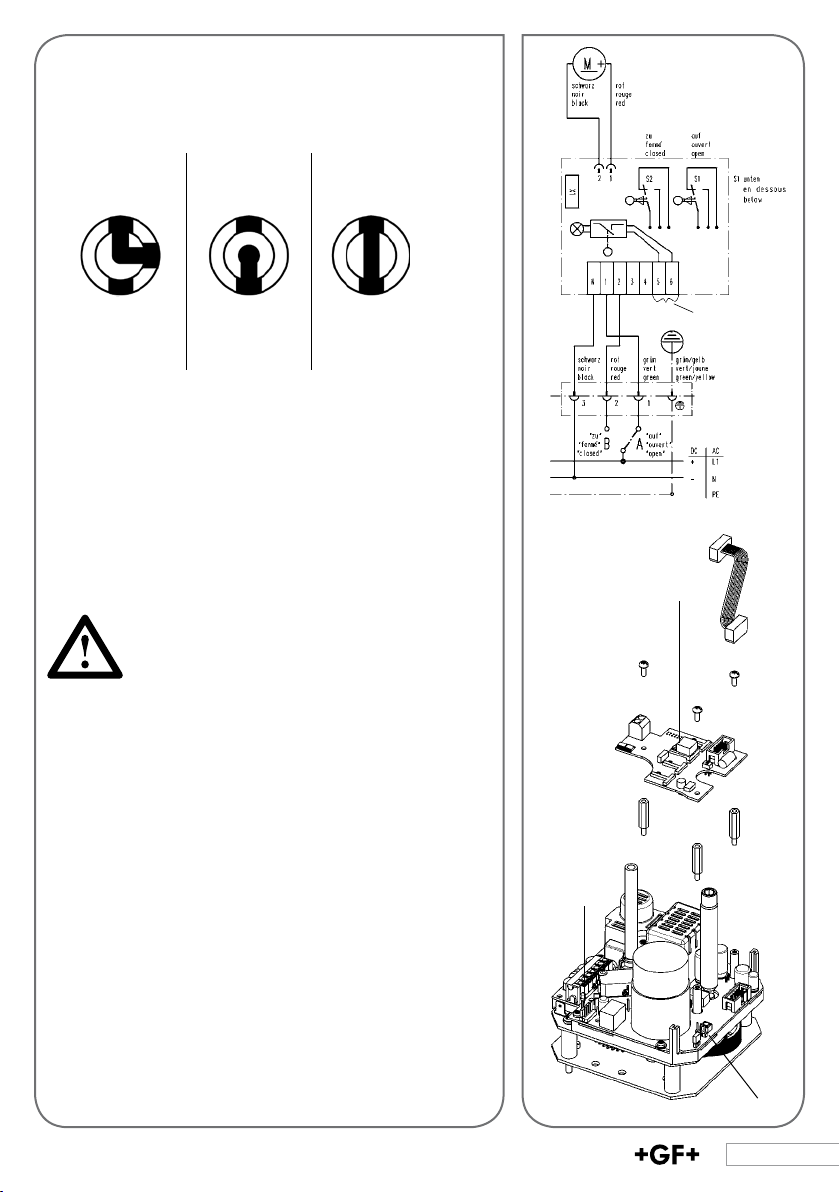
5.1 Wiring Diagram for Standard Version
Position indicator
3-way
horizontal
A
B
B−C
A−C
vertical
A
C
B
A−C
B−C
2-way
A
C
A−B
C
B
C
closed
open
Installation note
If the actuator is directly connected to the power supply, it
is necessary to install a disconnector between the actuator
and the power supply (do not disconnect the earth cable).
Cross-section of the external cables max. 1,5 mm2.
To avoid water owing into the actuator, make sure the cable
entry point is not upturned.
The EA 21/31/42 has a temperature control (ready-tooperate monitoring).
Due to the loading of the power supply capacitor
when rst time switching on the actuator current
peaks can occur for a few micro seconds. Therefore we recommend to connect the actuator in
accordance with accompanying wiring diagram.
5.2 Error message
If an error occurs, the red LED (8) on the base board will
light up.
If the monitoring print is installed, the LED (7) on the BCD
switch (10) which selected value has been exceeded will also
light up red.
Releai scontact
max. 2 4V
10
With all occurring error messages the ready-to-operate
signal will be off (terminals 5,6 no passage).
Eliminating the error message
Check the error cause, if necessar y carry out the appropriate maintenance.
To eliminate the message, activate the reset switch (9) on
the base board while the supply voltage is still connected
or briey disconnect the actuator from the mains voltage.
(Not effective with cycle counter)
8
9
41
Page 7
The two LEDs will go out and the actuator is ready to operate again.
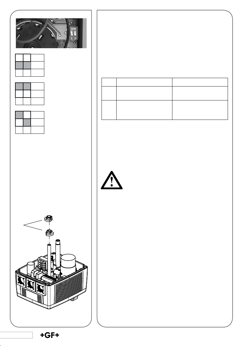
1 2
1 2
1 2
1
In case of malfunc-
ON
tion the actuator
OFF
remains on the
current position
(delivery state)
In case of malfunc-
ON
tion the actuator
OFF
turns to the OPEN
position
In case of
ON
malfunction the
OFF
actuator turns
to the CLOSED
position
S2: «Cl osed», top
S1: «Open», bottom
5.3 DIP switch in case of error
In case of an error the actuator can be set to the CLOSED or
the OPEN position with the help of the DIP switch. The DIP
switches need to be set as follows:
DIP 1 DIP 2
Position of DIP 2 effec-
ON
tive
Actuator remains in the
OFF
current position (DIP 2
Actuator turns to the
OPEN position
Actuator turns to the
CLOSED position
not effective)
(refer to explanation on the left)
6. Setting Up the Actuator
Attention
Check the following before connecting the actuator to the
mains:
• Does the main voltage correspond to the specications given on the type plate
• Has the actuator been connected correctly
(see Section 5.1)
• Fuse ≥ 6 A
Adjustments
If a complete valve is supplied by Georg Fischer, no further
adjustments are required. After installation by the customer
or after repair, the end positions should be checked and
adjusted if necessary.
42
Limit switch allocation
Switch S1 (bottom) opens at “open” position
Switch S2 (top) opens at “closed” position
Procedure
• Set both switching cams (1) to S1 and S2 so that the
rotating angle is less than 90°.
• Let the actuator turn until a limit switch is activated.
• By adjusting the respective switching cam, the end
position can be set since the actuator follows the cam.
Page 8
6.1 Emergency Manual Override
Assembly
1. Pull the crank (1) out of the bracket
2. Remove cover screw (2) with the provided crank (1)
3. Insert the crank in the hexagon shaft in the opening
2
After usage, please screw back on the
screw corer (2) to avoid liquids, humidity or
dust entering the actuator!
Function
Push the crank down to the stop. This activates a micro
switch that disconnects the actuator from the current. When
letting go the crank, the actuator is energized again.
With 9 revolutions, the actuator EA21 turns by 90°
With 27 revolutions the actuator EA31 turns by 90°
With 41 revolutions the actuator EA42 turns by 90°
Direction of rotation
Clockwise = CW = close
Counterclockwise = CCW = open
Note the “open” and “closed” position on
the optical indicator
Disconnect the connector plug.
If that is not possible, after usage pull the
crank rapidly out of the opening. (Actuator
might start turning)
1
43
Page 9
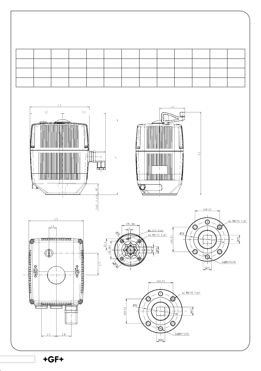
6.2 Dimensional drawings of the Electrical Actuator Type EA 21/31/42
22
L1 L2 L3 L4 L5 L6 L7 L8 L9 H1 H2 H3
150 82.5 108 64.3 122 16 49 33 33 167 20 188.5
EA21
150 82.5 108 64.3 122 16 49 33 33 190 25 211.5
EA31
150 82.5 108 64.3 122 16 49 33 33 208 25 229.5
EA42
EA21/F05 EA31/F07
EA42/F07
44
Page 10
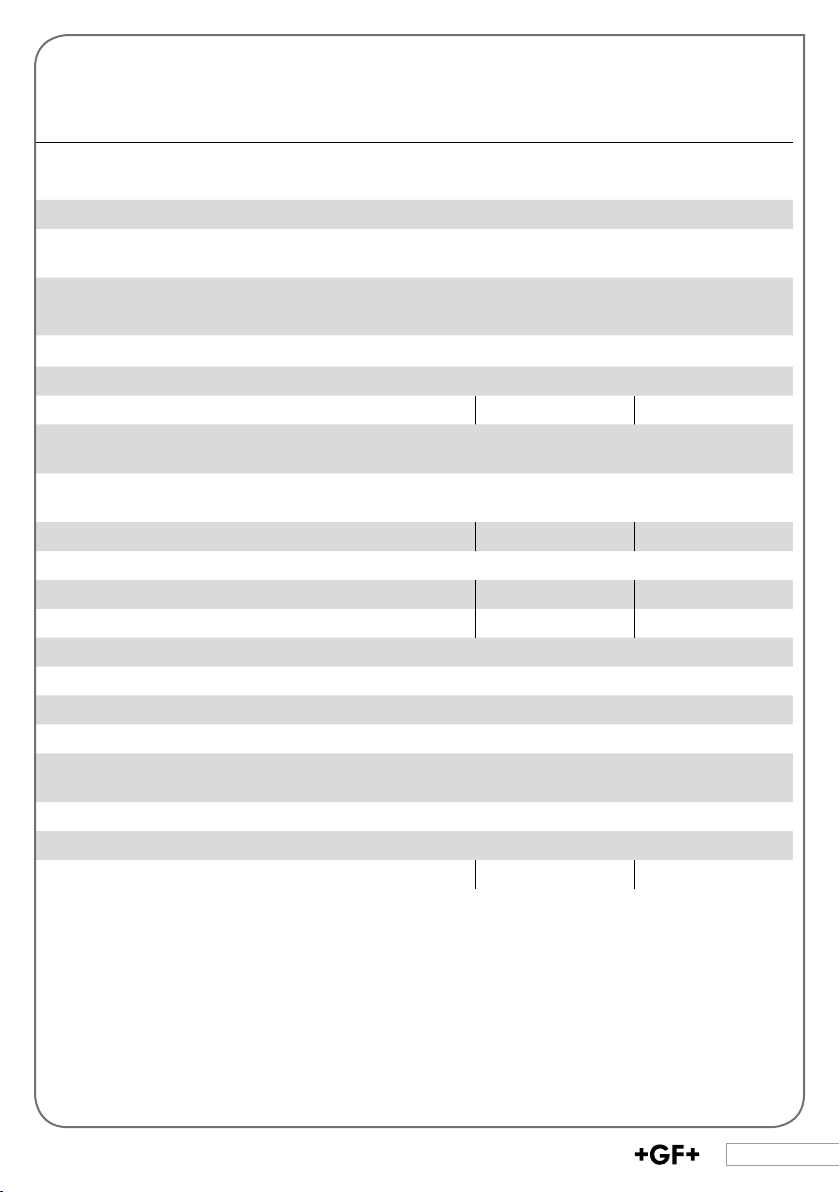
6.3 Technical Specications
EA21 EA31 EA42
Rated voltage 100 – 230V, 50/60 Hz
Rated voltage tolerance
Rated output @ 24V AC/DC
@ 100 – 230V AC
Electric impedance 230V, 100kΩ
24V = /24V, 50/60 Hz
+/- 10%
22 VA
40 VA
32 VA
40 VA
24V, 4.7kΩ
40 VA
60 VA
Altitude over NN (UL /CSA)
Protection class
< 2000m
IP 65 per EN 60529 *(3) UL/CSA: indoors use
Duty cycle 100% (6) 50% 35%
Overload protection current/time-dependent (resetting) *(1)
temperature dependent
Electrical connections Connector plug 3 P+E per DIN EN 175301-803
Cable gland M20 x 1,5 according to ISO 724
Nominal torque Mdn
10 Nm 60 Nm 100 Nm
Actuating angle max. 180°, set to 90°
Control time 5 s / 90° at Mdn 15 s / 90° at Mdn 25 s / 90° at Mdn
Peak torque 20Nm 120 Nm 250 Nm
Ambient temperature -10° to + 50°C (2) -10° to + 50°C (2)
Allowable humidity max. 90% relative humidity, non condensing
Pollution grade (4) 2
Over voltage category (4) II
Housing material PP breglass reinforced, ame retardant,external stainless
steel screws, non-losable
Position indication optical, integrated
Emergency manual override integrated
Flange pattern (5) F05 F07 F07
(1) Overl oad protec tion of the motor i s dimensioned so th at the motor and t he power supp ly board
are pro tected. As s oon as the loa d is in the torque
rang e, the actuato r runs again .
(2) For te mperatur es below -10°C as w ell as
conde nsation, th e heating elem ent no. 198 190
086 sh ould be built i n.
(3) Pro tection ra ting IP 67 for use of c able glands
and ver tical ins tallation
(4) Per E N 61010-1
(5) Per IS O 5211
(6) Reduc ed Duty cy cle for UL cer tication
45
Page 11
Wiring diagram
Heating element kit
7. Mounting and Connecting
Supplementary Kits
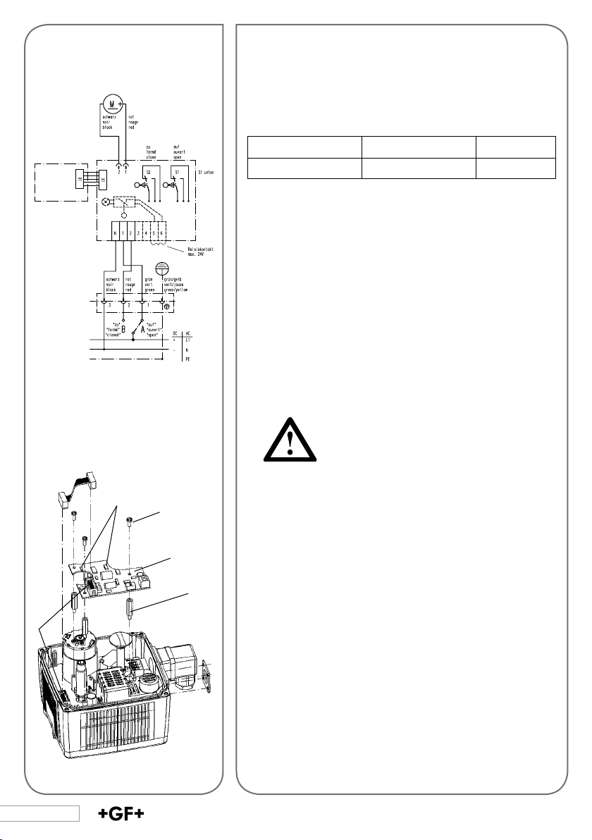
7.1 Heating Element
Description Technical data Code
Heating element 24 V= 199 190 086
The heating element is mounted on the base board and is
connected electrically via a at cable (X1). The temperature
is measured with a temperature sensor, which is mounted
on this element, and between approx. 0 - 5°C the heating
element is switched on.
Mounting the heating element (board)
1. Disconnect the actuator from the supply voltage.
2. Remove actuator cover.
3. Take the board out of its packaging and check for damages.
Do not touch the board itself. Electrostatic
discharge can damage the components.
4
46
LED on =
heating operation
2
4. Screw the three distance bolts (1) into the assembly
bolts. Screw hand-tight.
5. Fasten the board (3) on the distance bolts with the sup-
3
1
plied screws (2).
6. Plug the at cable into the X1 (4) connector.
7. Put the cover back onto the actuator.
8. Reconnect to supply voltage.
The heating element may not heat at temperatures over
+ 5 °C, but in case it is switched on it might heat up to
10-15 °C.
Page 12
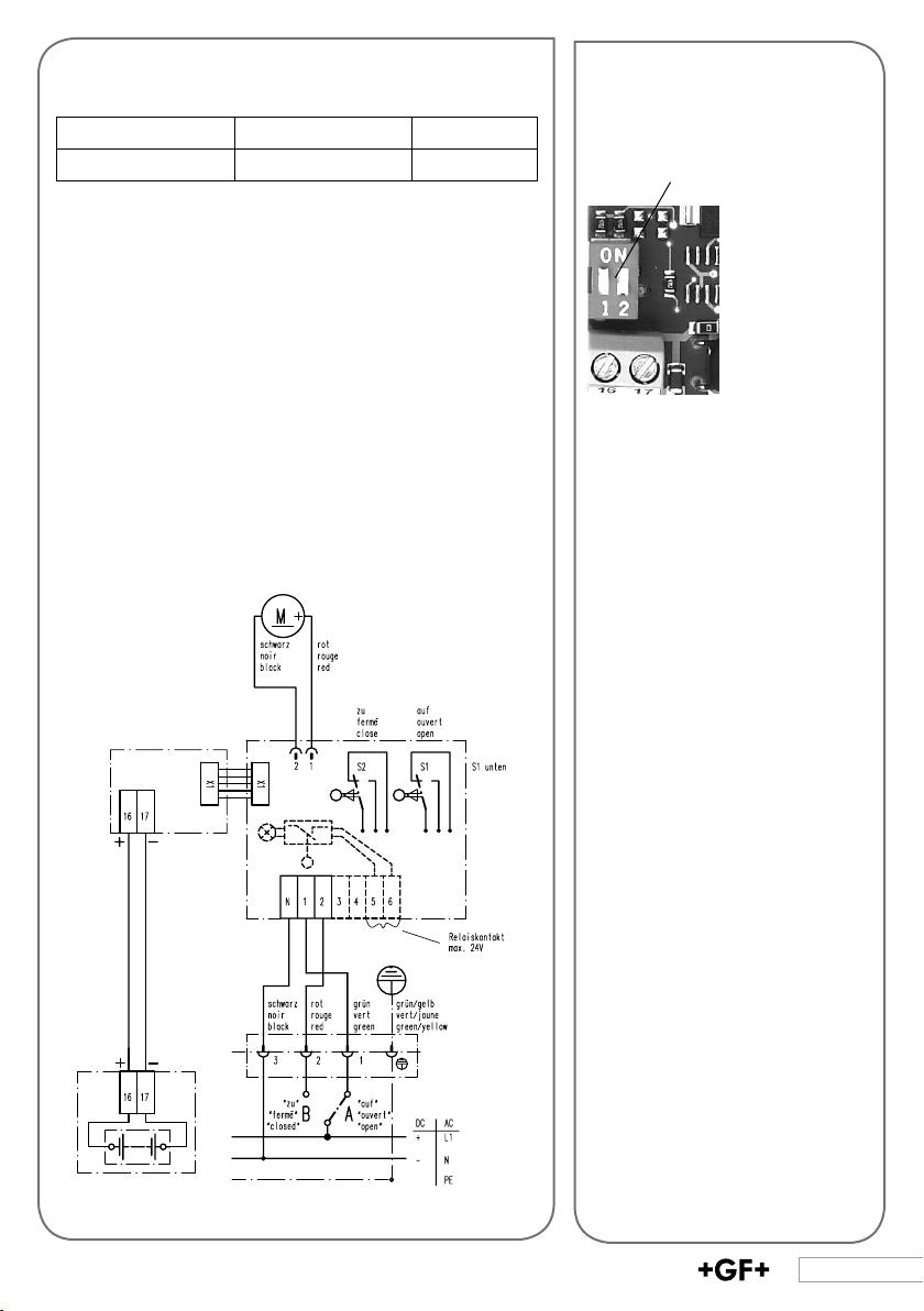
7.2 Fail-safe return
Description Technical data Code
Fail-safe return 24 V= 199 190 085
The fail-safe return unit is mounted on the base board and
is connected electrically via a at cable.
The fail-safe return unit is connected to the batter y via
a two-core wire. If the supply voltage is interrupted, the
electronics will switch to the storage battery automatically
after 5 sec. With the DIP switches (5), the functions “move
to the CLOSED position” or “move to the OPEN position” can
be selected.
Both switches ON: Actuator moves to OPEN
Both switches OFF: Actuator moves to CLOSED
The storage battery is charged continuously. Full charging
takes approximately 15 hours. Expected lifetime approx. 7
years.
DIP sw itch
Wiring diagram
Possible cycles per day:
EA 21 : 10
EA 31 : 04
EA 42 : 02
47
Page 13

Mounting the fail-safe return (board)
1. Disconnect the actuator from the supply voltage.
2. Take the board out of its packaging and check for damages.
Do not touch the board itself. Electrostatic discharge can
damage the components.
3. Screw the three distance bolts (1) into the assembly bolts. Screw hand-
tight.
4. Fasten the board (3) on the distance bolts with the supplied screws (2)
and washers.
5. Plug the at cable into the X1 connector.
6. Reconnect to supply voltage.
LED on
= normal operation / blinks with battery oper ation
2
3
LED on = b atter y operation
4
6
5
1
48
Battery
Rechargeable battery
Connect the battery via the second plug or cable gland to the terminals 16
and 17 (4). (we recommend 2x1.5mm2)
Attention must be given to the polarity. Charge the battery
for at least 15 hours.
In case the fail-safe return and the monitoring print are
installed both together, make sure that the adjustments will
not interfere one another.
Page 14

7.3 Additional Limit Switches
Wiring diagram
Description Technical
data
Kit with 2 additional*
limit switches Ag-Ni
Kit with 2 additional*
limit switches Au
Kit with 2 additional
limit switches NPN
Kit with 2 additional
limit switches PNP
Mounting set for 4 limit
switches
* The switches are wired as openers according to the diagram. It is possible for the customer to convert to closer by
rewiring.
(Terminal 8 > 7 and terminal 10 > 9).
250 V ~, 6 A 199 190 092
30 V =, 100 mA 199 190 093
10-30 V=,
100 mA
10-30 V=,
100 mA
Code
199 190 096
199 190 095
199 190 097
Mounting the limit switches
1. Disconnect the actuator from the supply voltage.
2. Remove the screws from the limit switches S1 and S2.
3. Mount the limit switch kit (1) on S1 and S2 as shown.
B)
B)
4. Tighten with the new, longer screws.
5. Mount the additional switching cams (2) as well as the
spacer rings (3).
1
2
3
49
Page 15

Setting the limit switch position
1. Reconnect the actuator to the supply voltage.
The switch position may only be set with an
extra-low voltage under 50 V.
2. Move the actuator to the two end positions and set the
respective switching points.
The switching cams can be adjusted with a screwdriver
size 2.
3. Disconnect the actuator from the supply voltage.
4. Connect limit switches.
5. Close the actuator with the housing cover and connect to
the supply voltage.
7.3.1 Additional 4 Limit Switches
Analog to the mounting instructions for the 2 additional limit
switches the EA 21/31/42 can be expanded to include 4 limit
switches.
The mounting sequence for the individual parts is equal to
the 2 additional limit switches.
50
For stability purposes additionally the
mounting set for 4 limit switches must also
be used. The fully assembled unit can be
seen in the picture below.
Page 16

7.4 Middle Positioning
Description Technical data Code
Middle positioning 199 190 094
The kit is mounted on the limit switches S1, S2 and serves to
move the actuator to a third position ( e.g. 3-way ball valve
into the middle position).
Wiring diagram
51
Page 17

Mounting the middle positioning kit
1. Disconnect the actuator from the supply voltage.
2. Remove the screws of the limit switches S1 and S2
3. Connect the plug of the kit to the four-pole slot (1).
Make sure that the multipoint socket connector of the plug
ts into the socket board of the four-pole plug.
4. Attach the two switches S3 and S4 of the kit to S1 and S2. When doing
this, switch S3 (assigned to PIN1, 2) must be down and switch S4 (PIN 3,
4) on top. (see wiring diagram).
5. Fasten the two switches S3 and S4 with the longer screws supplied.
S4
S3
(1)
52
Overview on activation
Actuator moves
in position
OPEN 1 S1 CCW*
CLOSED 2 S2 CW**
MIDDLE 3 S3 CCW
* CCW – Counter Clock Wise – G egen Uhr zeigersinn
** CW – Clock Wis e – Im Uhrzeigersin
> Move actuator to position “OPEN” (CCW): Put terminal 1 under current
> Switch S1 is activated.
> Move actuator to position “CLOSED” (CW): Put terminal 2 under current
> Switch S2 is activated.
> Move actuator to middle position (CCW / CW): Put terminal 3 under
current > Switch S3/S4 is activated.
Terminal
under current
Activated
switch
Direction of rotation of the actuator
S4 CW
Page 18

Setting the end positions
Setting the opening angle from 90° to 180°
• Turn switching cam 2 of switch S2 counter clockwise (top view) by 90°.
• Reconnect the actuator to the supply voltage
• Move the actuator into position “CLOSED” (terminal 2 under current)
• Turn cam 2 until reaching the desired position. (see position of the ball)
• Replace the standard position indicator by the new 3-way position indi
cator
Standard position indicator 3-way position indicator
-
Setting the middle position
• Move the actuator to the OPEN position (terminal 1 under current)
• Place the additional switching cam on the shaft. For this, rst remove
the position indicator again and put it back on again in the same position
after wards
• Place cam 3 upon cam 2 (cam 4 still stays on top of the switches)
• Put cam 3 into the same position as cam 2 and turn it clockwise by 90°
• Move actuator to the “middle” position (terminal 3 under current)
• Readjust cam 3 until reaching the desired middle position (see position
of the valve)
• Now Place cam 4 upon cam 3 in the same position as cam 3. Adjust cam
4 after wards. Its corner ank should activate switch S4 (S3 and S4 are
activated, the two nocks of the cams indicate to the opposite direction).
• Close the actuator with the housing cover. The middle position is now
set.
OPEN MIDDLE CLOSED
53
Page 19

BCD switch DIP switch
1 5 2 3 4
7.5 Monitoring print
Description Technical data Code
Monitoring print 199 190 099
The monitoring print is mounted on the base board and is
connected electrically with a at cable. The monitoring print
enables ve functions:
1. Cycle time extension
2. Cycle time monitoring
3. Monitoring a selected maximum number of cycles
4. Monitoring a selected maximum of motor current
5. Position feedback signal 4-20mA (see page 26)
These monitor settings are made via the BCD switches 1 to
4. They are described in the following pages. The switches
must be plugged in order for the function to be active. The
functions work independently of one another. BCD switches
(1 to 4) can be connected individually.
1. Cycle time extention (Vario)
2. Cycle time monitoring
3. Cycle counter
4. Current monitoring
5. Position feedback
Wiring diagram
54
Page 20

Mounting the monitoring print
1. Disconnect the actuator from the supply voltage.
2. Take the board out of the packaging and check for dama-
ges.
Do not touch the board itself. Electrostatic
discharge can damage the components.
3. Screw the three distance bolts (1) into the assembly bolts.
Hand-tighten.
4. Fasten the board (3) to the distance bolts (1) with the
screws (2).
5. Insert the BCD switch (4) for the desired function. Secure
it with the help of the nipple supplied.
6. Select the desired switch setting with a screwdriver.
Monitoring print kit
4
3
2
1
7
2
4
3
1
7. Plug the at cable into the X1 (7) connector.
8. Reconnect to supply voltage.
The board has been connected correctly, when:
1. The LED (9) above the BCD switches blinks green.
2. The LED (6) lights up green.
9 6
8 5
4
3
2
1
1. Cycle time extention (Vario)
2. Cycle time monitoring
3. Cycle counter
4. Current monitoring
5. Position feedback
55
Page 21

Error message
10
If an error occurs, the red LED (8) on the base board lights
up.
In case the monitoring print is installed, the LED (10) on the
BCD switch which selected value has been exceeded will
also light up red.
With all occurring error messages the ready-to-operate
signal will be off.
Eliminating the error message
Check the error cause, if necessar y carry out the appropriate maintenance.
To eliminate the message, activate the reset switch (9) on
8
the base board while the supply voltage is still connected
or briey disconnect the actuator from the mains voltage.
The two LEDs will go out and the actuator is ready to operate again.
The ready-to-operate module can react the
fail-safe mode as well. Resetting the error
message does not reset the cycle counter!
1 2
1 2
1 2
56
In case of malfunc-
ON
tion the actuator
OFF
remains in its
position (delivery
state)
In case of malfunc-
ON
tion the actuator
OFF
moves to the OPEN
position
In case of malfunc-
ON
tion the actuator
OFF
moves to the
CLOSED position
9
DIP switch in case of error
With the help of the DIP switch, the actuator can be moved
to the CLOSED or OPEN position in case of an error. For this,
the DIP switches need to be adjusted as follows:
DIP 1 DIP 2
ON Position of DIP 2
effective
OFF Actuator remains in its
position
Actuator moves to the
OPEN position
Actuator moves to the
CLOSED position
(DIP 2 not effective)
(please refer to example on the left)
Page 22

Cycle time extension (Vario)
Description Technical data Code
Cycle time extension 199 190 080
The cycle time extension increases the cycle time of the
electric actuator. To do this, the actuator rides clocked to
the end positions (OPEN or CLOSED).
The corresponding values are contained in the following
table. These values apply for 90° angle. Cycle time without
BCD: 5s for 90° (EA21); 15s for 90° (EA31); 25s for 90° (EA42)
Switch setting Cycle time monitoring [s]
EA21 EA31 EA42
0 Deli very posi tion 8 20 30
1 12 25 35
2 15 30 40
3 19 35 45
4 25 40 50
5 30 50 55
6 35 60 65
7 35 60 75
The switch positions 8 – 9 have the function of position 7.
The extension of the cycle time is also active in case of failure or reset operation.
57
Page 23

Cycle time monitoring
Description Technical data Code
Cycle time
monitoring
Cycle time monitoring monitors the duration of a pre-set
cycle time of the electric actuator. If the cycle exceeds the
pre-set time, a failure is reported (see error message, page
20). For the corresponding value please refer to the table
below (values are valid for 90° actuation).
Switch setting Cycle time monitoring [s]
EA21 EA31 EA42
0 7 10 15
1 10 D elivery
posit ion
2 15 20 25
3 20 25 Del ivery
4 25 30 35
5 30 35 40 Del ivery
6 35 40 50
7 40 45 60
5 6 8 9
8 45 55 70
9 50 70 85
199 190 082
15 20
30
posit ion
posit ion
1 2
1 2
58
Both switches on ON
ON
- Error message
OFF
without stopping the
actuator
Both switches on OFF
ON
- Error message with
OFF
stopping the actuator
(delivery position)
Cycle counter
Description Technical data Code
Cycle counter 199 190 083
This function allows setting a desired number of cycles. As
soon as the number of cycles exceeds the set value, an error
is reported (see error message, page 20). With the help of
the DIP switch (8) on the monitoring print it can be preset, if
the actuator should keep moving in this case, or if it should
move to its security position and remain there. (refer to
section error message).
Page 24

Switch setting Number of cycles
0 1
1 10.000
2 20.000
3 30.000 (3)
4 40.000 (2)
5 50.000 (1)
6 60.000
7 70.000
8 80.000
9 90.000
Current monitoring
Description Technical data Code
Current
monitoring
This function monitors the motor current. If the motor
current is greater than the pre-set value, a malfunction is
repor ted.
Switch setting Max. motor current/mA
0 200
1 400
2 600 (1)
3 800
4 1.000 (2)
5 1.200
6 1.400 (3)
7 1.600
8 1.800
9 2.000
199 190 081
(1) Delivery position EA21
(2) Delivery position EA31
(3) Delivery position EA42
Reset „Number of Cycles“
Turn the BCD-Switch in the Position O (Position corresponding
to 1 Cycle). Drive the actuator
into CLOSE Position and back to
OPEN Position. The LED lights
up. Press the reset button on the
basic print and the cycle counter
will be cleared. Now the BCD
Switch can be set to the desired
number of cycles again. (refer
to table)
When setting the BCD switches, make sure
that the set function do not block one another.
Example BCD1 cycle timeposition position 3 = 19s
EA21: BCD2 cycle time monitoring position 0 = 7s
59
Page 25

7.6 Position Signalization
Description Technical data Code
Position
signalization
The position signalization enables determining the exact
mechanical position of a valve. Output signal is a current of
4 – 20 mA. (4mA-CLOSED, 20mA-OPEN).
The position signalization can be combined with the positioner or the monitoring print.
The position signalization board is mounted on the limit
switches S1, S2 and is connected electrically to the positioner or the monitoring print via a system cable.
Mounting the position signalization
1. Disconnect the actuator from the supply voltage.
1
2
3
2. Remove the screws of the limit switches S1 and S2.
3. Remove the position indicator (1).
4. Place the position signalization board in the position
shown on S1 and S2 and fasten with the longer screws.
5. Insert the toric magnet (3) so that the notches are on the
top.
Again place the position indicator (1) on the axis in one of
the end positions.
199 190 084
60
6. Connect the position signalization board to the controller or monitoring print via the system cable (2).
Reconnect to the power supply.
The board has been connected correctly when the LED
(4) lights up green.
If the position signalization is used
together with additional limit switches,
the position signalization as to be in
stalled above the limit switches.
Page 26

Setting the position signalization
For the position sensor (4) to recognize the OPEN and
CLOSED positions, a single learning run with 360° must be
done. After the learning run, the OPEN and CLOSED positions are set.
Further learning runs can be done between the end positions (depending on the switching cams S1 and S2).
The way how the jumper is placed on the position signalization determines if the learning run happens with 360° or if it
happens between the end positions.
Jumper connects both PINs: learning run 360°
Jumper doesn’t connect the PINs: learning run bet
ween the end positions
When position signalization is mounted ex
factory, a learning run with 360° has been
already done. In this case the jumper is
placed on only one PIN. When the position
signalization is mounted by the customer a
360° learning run has to be done. Therefore
the two PINs need to be connected by the
jumper.
Subsequent modications on the switching
cams requires a new learning run.
7
4
5
6
Learning run 360° (Position signalization
kit subsequently installed)
It is necessary to separate the actuator from
the valve, to avoid damage to the valve. Before doing the learning run set the jumper so
it connects the two PINs. Complete learning
run. Then reset the jumper to its original
position and remount the actuator.
Doing a learning run
Press the button (5) on the board for ca. 2s. (The LED (6) will
go out briey. As soon as the LED lights up again, release
the button). The actuator will do a learning run with several
longer pauses.
61
Page 27

During this run, the LED (6) will blink. While the LED (6) is blinking, the
actuator is in the learning mode. The learning run is only nished when the
LED lights continuously.
7
If the position signalization is combined with the monitoring print, the
output signal 4 – 20 mA can be processed on the terminals 18, 19 (7) on the
board of the monitoring print. (4 mA > CLOSED / 20 mA > OPEN).
If the position signalization is connected to the positioner, the latter will
process the signal.
7.7 Positioner
Description Technical data Code
Positioner type PE 25 199 190 100
The positioner type PE 25 controls a user-dened valve position proportional to a given set value. This can be 0-10V or 4-20mA.
Power supply needs to be galvanically isolated.
62
The return of the valve position (actual value) is realized with the position
signalization.
The control parameters are pre-set ex factor y and do not need to be changed.
Page 28

Signal conguration
The four DIP switches on the controller print serve for the
conguration of the signals.
DIP switch:
ON
OFF
S1 S2 S 3 S4
Switch combination
Signal type S1 S2
0-10 V OFF OFF
4-20 mA ON ON
S3: ON: input inverted
OFF: input not inverted
S4: ON: use S3L Master
OFF: use S3L Slave
Example:
Set signal value 4 – 20 mA, not inverted, use S3L Slave
ON
OFF
S1 S2 S 3 S4
DIP switch
LED‘s
63
Page 29

Description Technical data Code
Positioner type PE 25 galvanic isolated 199 190 101
The positioner type PE 25 controls a user-dened valve position proportional to a given set value. This can be 0-10V or 4-20mA.
The return of the valve position (actual value) is realized with the position
signalization. The control parameters are pre-set ex factory and do not
need to be changed.
64
The return of the valve position (actual value) is realized with the position
signalization.
The control parameters are pre-set ex factor y and do not need to be changed.
Page 30

Signal conguration
The four DIP switches on each of the three switch blocks
on the controller print serve for the conguration of the
signals.
DIP Schalter Block 1 - 3:
ON
OFF
S1 S2 S 3 S4
Switch combination
DIP switch
Block 1
S1 S2 S 3 S4
DIP switch
Block 2
Signal type S1 S2
0-10 V OFF OFF
4-20 mA ON ON
S3: ON: input inverted
OFF: input not inverted
S4: ON: use S3L Master
OFF: use S3L Slave
DIP switch
Block 3
S1 S2 S 3 S4
Example:
Set signal value 4 – 20 mA,
not inverted, use S3L Slave
DIP Switch Block 1
All switches must
ON
be set to OFF
OFF
S1 must be
ON
set to ON
OFF
S2-S4 must be
set to OFF
S1 S2 S 3 S4
DIP Switch Block 2DIP Switch Block 3
ON
OFF
LED‘s
65
Page 31

Mounting the positioner
1. Disconnect the actuator from the supply
voltage.
2. Take the controller board out of the packaging and
check for damages.
Do not touch the board itself. Electrostatic
discharge can damage the components.
3. Place the board vertically on the back side of the base
board on plug X1. (see page 47)
Make sure that the board is inserted exac
tly in the guides at the side.
Setting the position signalization see Section 9.6
Connecting the positioner
For the positioner to receive the set value signal, connect
the terminals of the set value inputs 20 to 23 for the corresponding values. (see table below) Cable cross-sectional
area max. 1.5mm
2.
EA 21 mit montiertem Stellungsregler und Positionserfassung.
66
Mind the conguration of the set value (see signal conguration):
Terminal assignment Positioner 199 190 100:
20 SET value input current
21 SET value input voltage
22 -
23 SET value input ground
30 Position signalization signal
31 Position signalization ground
Page 32

Terminal assignment Positioner 199 190 101:
27 SET value input current / voltage
28 Output 12 V DC
29 SET value input ground
30 Position signalization signal
31 Position signalization ground
Mind the conguration of the set value
The 4 – 20 mA current signal at the terminals 30, 31 can be
evaluated, if necessar y.
(4 mA: CLOSED; 20 mA: OPEN)
When the set value and the position indicator have been
connected, reconnect the actuator to the supply voltage (see
wiring diagram).
The positioner has been connected correctly, when the
green LEDs 1,2, and 4 light up green.
If the LED 3 lights red, the controller is not working (see
LED combination).
Check the connections if necessar y and make sure the
poling of the set input is correct.
LED combination
Colour
LED
green green red green
1 2 3 4
After the positioner is correctly connected, do a learning
run.
67
Page 33

4
7
Setting the position signalization
For the position sensor (4) to recognize the OPEN and
CLOSED positions, a single learning run with 360° must
5
6
be done. After the learning run, the OPEN and CLOSED
positions are set.
Further learning runs can be done between the end posi-
tions (depending on the switching cams S1 and S2).
The way how the jumper is placed on the position signaliza-
tion determines if the learning run happens with 360° or if it
happens between the end positions.
Jumper (7) connects both PINs: learning run 360°
Jumper doesn’t connect the PINs: learning run between
the end positions
When position signalization is mounted ex
factory, a learning run with 360° has been
already done. In this case the jumper is
placed on only one PIN. When the position
signalization is mounted by the customer a
360° learning run has to be done. Therefore
the two PINs need to be connected by the
jumper.
Subsequent modications on the switching
cams requires a new learning run.
68
Learning run 360° (Position signalization
kit subsequently installed)
It is necessary to separate the actuator from
the valve, to avoid damage to the valve.
Before doing the learning run set the jumper so it connects
the two PINs. Complete learning run. Then reset the jumper
to its original position and remount the actuator.
Doing a learning run
Press the button (5) on the board for ca. 2s. (The LED (6) will
go out briey. As soon as the LED lights up again, release
the button). The actuator will do a learning run.
During this run, the LED (6) will blink. While the LED (6) is
blinking, the actuator is in the learning mode. The learning
run is only nished correctly when the LED lights continuously.
Page 34

69
Page 35

8. TROUBLESHOOTING
Problem Possible causes Remedy
Motor does not run no mains voltage available error at customer side
(terminals 1,2,3)
internal wiring error check wiring of actuator
switching cams S1 and S2 see point 6
set incorrectly
motor blocked
Motor only runs in limit switch defective replace limit switch
one direction
Overload protection reacts
(self-resetting)
Valve does not close or
open correctly not adjustedt
torque of valve too high clean and lubricate valve
duty cycle too high increase cycle time
switching cams S1 and/or S2 see point 6
use emergency manual override,
check the valve
reduce ambient temperature
For ser vice please contact the specialist at your Georg Fischer sales company.
In case an end position is not reached, the actuator shuts off automatically after
2 minutes and reports error message.
70
Page 36

Ordering Information
Description Code
Actuator EA21 100–230 V~ 198 150 182
Actuator EA21 24 V=/~ 198 150 183
Actuator EA31 100–230 V~ 198 150 184
Actuator EA31 24 V=/~ 198 150 185
Actuator EA42 100–230 V~ 198 150 186
Actuator EA42 24 V=/~ 198 150 187
Limit switch kit Ag-Ni 199 190 092
Limit switch kit Au 199 190 093
Limit switch kit Middle Position 199 190 094
Limit switch kit PNP 199 190 095
Limit switch kit NPN 199 190 096
Mounting set for 4 limit switches 199 190 097
Fail-safe return incl. battery kit 199 190 085
Heating element 199 190 086
Heating element + fail-safe return incl. battery kit 199 190 087
Monitoring print 199 190 099
Cycle time extension 199 190 080
Cycle time monitoring 199 190 082
Cycle counter 199 190 083
Motor current monitoring
Position signalization 199 190 084
Positioner PE 25 199 190 100
Positioner PE 25 galvanic isolated 199 190 101
Testing adaptor kit for RS 232 inter face 198 151 426
Battery kit (spare) 198 151 317
Crank 198 151 307
Cover screw kit
Kit of plugs 198 000 502
Adaptor Set for F05 SW14/11 198 000 587
Adaptor SW14 for F05 198 204 057
Reduction SW11 for F05 198 803 145
199 190 081
198 000 503
71
Page 37

Notizen/Notice/Note
72
Page 38

Notizen/Notice/Note
73
Page 39

700.278.045
GMST 5886/1/4a (5.07)
© Georg Fischer Piping Systems Ltd
CH-8201 Schaffhausen/Switzerland, 2006
Printed in Switzerland
 Loading...