

Page 1
Instruction Manual
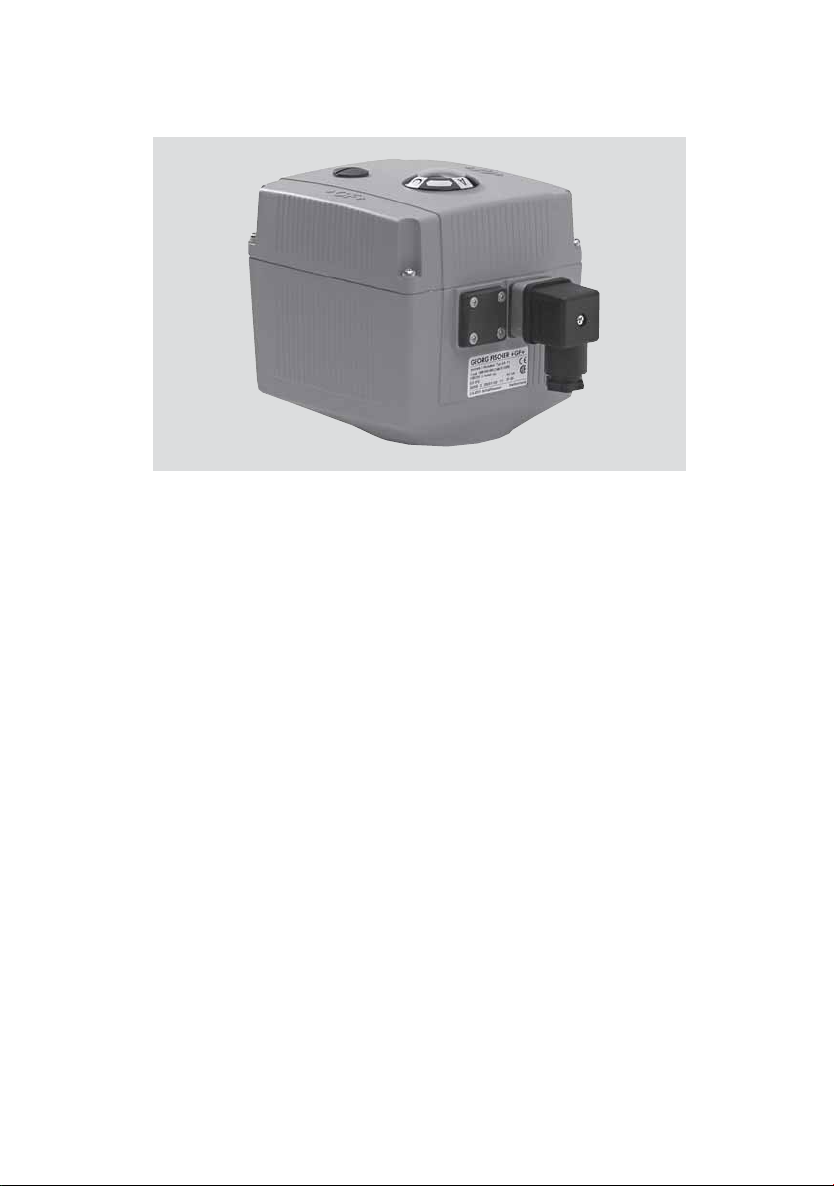
Electrical Actuator Unit
Type EA ¢1
¥ ‡
Page 2

The technical data is not
binding and not an expressly
warranted characteristic of the
goods. It is subject to change.
Please consult our General
Conditions of Supply.
58
¥ ‡
Page 3

Table of Contents
Page
1. Introduction/General Information 60
2. Manufacturer‘s Declaration 60
3. Intended Use 61
4. Safety Tips 62
4.1 Due Care Required of the Operator
4.2 Special Hazards
4.3 Transport and Storage
5. Actuator Design 64
5.1 Wiring Diagram for Standard Version
6. Valve Design 66
6.1 Mounting on the Ball Valve ¢07
6.2 Overview of Ball Valve System
Type ¢07
7. Setting Up the Actuator/Valve 70
7.1 Emergency Manual Override
8. Technical Specifications for EA ¢1 72
9. Mounting and Connecting 73
the Supplementary Kits
9.1 Heating Element
9.2 Fail-safe Return
9.3 Additional Limit Switches
10. Fastening Plate 82
11. Troubleshooting 83
12. Subcomponents/Spare Parts 84
¥ ‡
59
Page 4
¢. Introduction
This instruction manual contains all the pertinent
information on the design, installation and operation of the electrical actuator type EA 11 .
General Information
Hazard notices
Hazard notices are used in this manual to warn you
of possible injuries or damages to property. Please
read and abide by these warnings at all times!
Warning symbols
Danger
Warning
Caution
Meaning
Imminent acute danger!
Failure to comply could result in death
or extremely serious injury.
Possible acute danger!
Failure to comply could result in
serious injury.
Dangerous situation!
Failure to comply could lead to injury
or damage to property.
2. EC Manufacturer‘s Declaration
The manufacturer, Georg Fischer Piping Systems
Ltd, CH-8201 Schaffhausen, declares that the
electrical actuator EA 11 is not a ready-to-use
machine in the sense of the EC Machine Directive
and cannot therefore meet all the requirements of
this directive.
60
¥ ‡
Page 5
Operation of these actuators is prohibited until
conformity of the entire system into which the
valve and the actuator have been installed is
established according to the EC Directives listed
below.
Applicable EC Directives:
72/23 EEC EC Low Voltage Directive
89/336 EEC EC Directive on Electromagnetic
Compatibility
Modifications to the actuator which have an
effect on the technical data given in this instruction manual and its intended use, i.e. significantly alter the actuator, render this
manufacturer‘s declaration null and void.
3. Intended Use
Warning
When mounted on a valve and connected to a
system control, the purpose of this actuator is to
ł actuate valves with 90° pivoting (ball valves and
butterfly valves),
ł indicate the previously calibrated end positions
of the valve via electrical signal to the system
control (accessory), and
ł provided that the actuator data corresponds to
the electrical control and the valve and
ł in case of interruption in the supply voltage,
warrant that the actuator/valve remains in the
current position. Please use emergency manual
override or install fail-safe return.
The actuator is not intended for uses other than
those listed here. If the instructions contained in this
manual are not observed, the manufacturer is
excluded from all liability for the above mentioned
products.
¥ ‡
Warning
61
Page 6
Warning
4. Safety Tips
4.1 Due care required of the operator
The actuator described herein was designed and
manufactured with consideration to the respective
harmonized European standards. It corresponds to
the latest technology and the technical specifications contained under Section 8.
Safety on the job can, however, only be realized if
the operator warrants that
ł the actuator is only used as indicated under
Section 3,
ł he is familiar with this instruction manual and the
manual of the corresponding valve and adheres
to the instructions contained therein and
ł he has taken the necessary measures against
electrostatic influence.
4.2 Special hazards
62
Warning
Under normal conditions, the actuator may only
be operated with the cover closed.
If work is performed on the actuator with the
cover removed, the supply and control voltage
must first be disconnected. Adjustments, which
need to be done in the energized state, should
be carried out with special insulated tools.
In addition, the operating instructions of the
manual valve must be observed. They are an
integral component of this manual.
¥ ‡
Page 7

4.3 Transport and storage
The actuators must be handled, transported and
stored with care. Please note the following points:
ł The actuators should be transported and/or
stored in their original unopened packaging.
ł The actuators must be protected from harmful
physical influences such as dust, heat (humidity).
ł It is important that the connections are neither
damaged by mechanical nor thermal influences.
ł Prior to installation, the actuators should be in-
spected for transport damages. Damaged actu-
ators must not be installed.
Warning
¥ ‡
63
Page 8
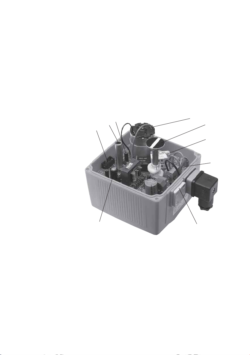
5. Actuator Design
The standard version of the EA 11 electrical
actuator consists of the following elements:
gear unit, direct current motor, electrical board,
and components for end position limiting.
For special applications, the actuator can be
equipped additionally with various supplementary
kits (see Section 9).
/
)
V
$
&
1 Limit switches S1 and S2
2 Direct current motor
3 Optical position indicator
4 Plug for accessories
5 Terminal strip for external connections
max. ¢.5 mm
2
6 Electrical supply unit, without protection
against accidental contact
7 Shaft for emergency manual override
8 Connections for DIN plug or
cable gland
9 Assembly bolt for accessories
§
!
%
(
64
¥ ‡
Page 9
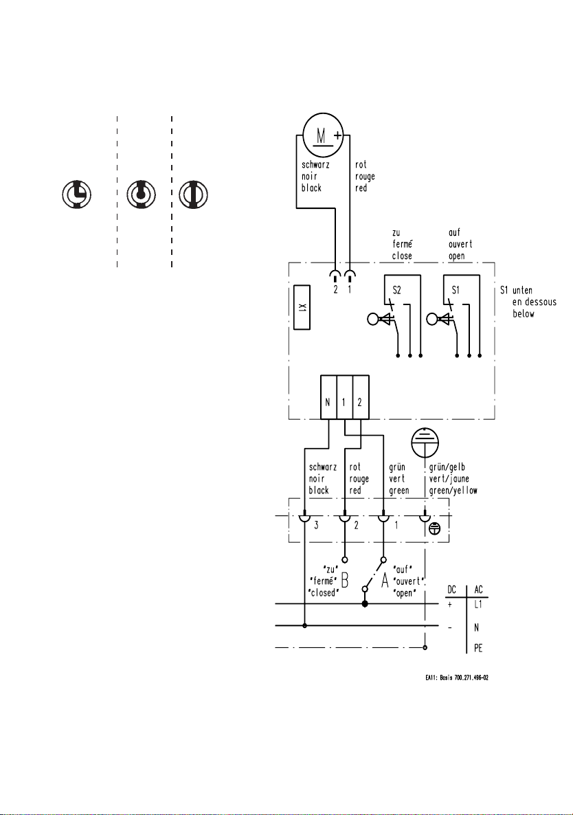
5.1 Wiring Diagram for Standard Version
Position indicator
2/2-way3/2-way
horizontal
A
B
B–C
A–C
vertical
A
C
B
B–C
A–C
A
C
B
C
A–B
C
closed
open
Installation note
If the actuator is connected
direct to the power-supply,
it is necessary to install a
switch-disconnector between
the actuator and the powersupply (do not disconnect the
earthcable).
To avoid water flowing into
the actuator it is necessary
that the cable insertion ist not
upturned.
¥ ‡
65
Page 10
6. Valve Design
The EA ¢1 electrical actuator can be mounted on
ball valves type 546, DN10–50, by using the correct coupling piece and selecting a suitable adapter plate with clamps.
The actuators are supplied ex works in the «open»
position. See Section 6.¢ for the individual assembly
components required for the ball valve type ¢07.
Both end positions in the actuator have been preset
in the factory. It is necessary to readjust these after
installation at the customer (see Section 7).
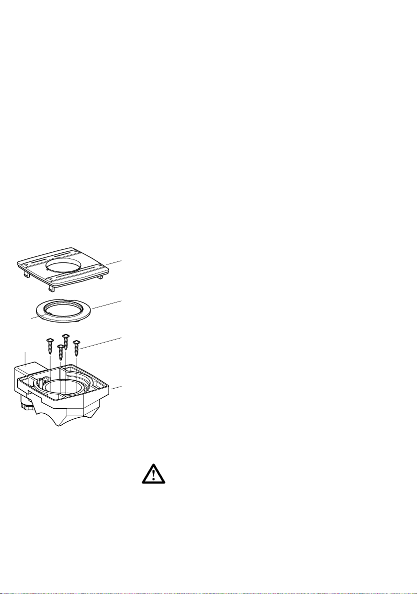
How to assemble (see Fig. 6.1)
3a
close
open
Screw the adapter plate with the fixed clamps
2
tightly onto the actuator (note the cam positions).
3
Mount the multifunctional module on the ball valve.
1 Housing
2 Housing cover
3 Indexing disk* with switching cams 3a
4
5
4 Screws
5 Connector plug 3P + E per DIN EN
175301-803* (formerly DIN 43650)
1
* only for MF module version with pre-assembled
microswitches
Remove housing cover (2).
The MF module can be mounted on the ball
valve type 546 in the opened or closed
position.
66
¥ ‡
Page 11

Spigot is asymmetrical.
The spigot position must be idential with one of the
two illustrations.
A Stem position for closed ball valve
B Stem position for open ball valve
Place the MF module on the ball valve
Make sure the contours match!
Note the square (a) and round (b) contours as well
as the position of the asymmetrical recesses (c) of
the stem.
Tighten the 4 pre-assembled screws (Torx).
The MF module is now firmly connected with the
ball valve.
Insert the coupling and the coupling piece* in the
multifunctional module.
Fasten the actuator with the adapter plate to the
multifunctional housing using the provided clamps.
*coupling piece only for DN10–25
Actuator and valve must have the same position, «open» or «closed».
¥ ‡
67
Page 12

Actuator
Type EA ¢1
Coupling piece
Adapter plate
PT-Schr KA 4x¢6
Clamp
Allen screws
Coupling
6.1 Ball Valve Type ¢07
Screws
Multifunctional module
(without microswitches)
Ball valve type 546
68
¥ ‡
Page 13

6.2 Overview of Ball Valve System
Type ¢07
1 Actuator type EA ¢1
2 Coupling piece DN10–25
3 Adapter plate DN10–50
4 Multifunctional module DN10–50
5 Ball valve type 546 DN10–50
1
2
3
4
DN 10/155DN 20
Note: Screw saving
The actuator fixing screws are assured with «Locitite 243» or equivalent.
Note: Mounting of coupling and coupling piece
First plug the coupling piece into the actuator. Then fix the adapter plate
with four screws on the actuator. Next push the coupling into the coupling piece.
The coupling with the mounted coupling piece does not fit through the
hole of the adapter plate!
2
3
4
DN 25
5
5
3
4
DN 32
5
DN 40
5
3
4
DN50
5
¥ ‡
69
Page 14

7. Setting Up the Actuator
Attention
Check the following before connecting the actuator
to the mains:
ł Does the mains voltage correspond to the speci-
fications given on the typeplate
ł Has the actuator been connected correctly
(see Section 5.1)
Adjustments
If a complete valve is supplied by Georg Fischer,
no further adjustments are required.
After installation by the customer or after repair
work, the end positions should be checked and if
necessary adjusted.
Limit switch allocation
Switch S1 (bottom) opens at «open» position
Switch S2 (top) opens at «closed» position
Procedure
Set both switching cams (1) to S1* and S2* so that
the rotating angle is less than 90°.
Let the actuator turn until a limit switch is activated.
By adjusting the respective switching cam, the end
position can be set since the actuator follows the
cam.
70
* S1: «open», bottom
S2: «closed», top
!
¥ ‡
Page 15

7.1 Emergency Manual Override
Assembly and function
Assembly
Pull the crank (1) out of the retainer
Remove cover screw (2) with the crank (1)
Insert the crank in the hexagon shaft* under the
opening
V
* see illustration, page 60, no. 7
Function
Push the crank down to the stop.
With nine revolutions, the ball is rotated by 90° .
Direction of rotation:
Clockwise = CW = close
Counterclockwise = CCW = open
Note the «open» and «closed» position
on the optical indicator.
Disconnect the connector plug.
If that is not possible, pull the crank
rapidly out of the opening.
!
¥ ‡
71
Page 16

8. Technical Specifications
Actuator EA ¢1
Rated voltage 100–230 V, 50/60 Hz
24 V =/24 V, 50/60 Hz
Rated voltage tolerance w 10%
Rated output 22 VA at 24 V AC/DC
40 VA at 100–230 V AC
Electric impedance 230V, 100k
24V, 4k7
Altitude l 2000m
Protection class IP 65 per EN 60529
3)
UL/CSA: Indoor use
Duty cycle 40% at 25 °C / ¢5 min
Overload protection current/time dependent
(resetting)
1)
Electrical connections Connector plug 3 P+E per
DIN EN 175301-803
(formerly DIN 43650)
additional cable entry point
for PG ¢1
Control time 5 s / 90° at Mdn
Actuating angle max. 270°, set to 90°
Nominal torque 10 Nm
Peak torque 20 Nm
Ambient temperature –10° to +45 °C
Allowable humidity max. 80% up to 31 °C
Pollutiongrade
Overvoltage-category
5)
5)
2
II
2)
4)
Housing materials PP fiberglass reinforced,
flame retardant,
external stainless steel screws
Position indicator optical, integrated
Emergency manual override integrated
72
1)
Overload protection of the motor is dimensioned so that the motor
and the power supply board are protected. As soon as the load is
in the torque range, the actuator runs again.
2)
For temperatures below –10 °C as well as condensation, the
heating element no. 198 ¢90 086 should be built in (see Section 9.1).
3)
Protection rating IP67 for use of cable glands and vertical
installation.
4)
Linear decreasing to 50% relative humidity with 40 °C
5)
Per EN 6¢0¢0-¢
¥ ‡
Page 17

9. Mounting and Connecting
Supplementary Kits
9.1 Heating element
Description Technical data Code
Heating element 24 V= 199 190 086
Wiring diagram
The heating element is mounted on the base board
and is connected electrically via a flat cable (X1).
The temperature is measured with a temperature
sensor, which is mounted on this element, and
between approx. 0–5 °C the heating element is
switched on or off, respectively.
¥ ‡
73
Page 18

LED shines
= heating operation
Heating element kit
LED shines
= normal operation
74
¥ ‡
Page 19

Mounting the heating element (board)
Disconnect the actuator from the supply voltage.
Take the board out of its packaging and
check for damages.
Do not touch the board itself. Electrostatic
discharge can damage the components.
Screw the three distance bolts (1) into the
assembly bolts.
Screw hand-tight.
Fasten the board (3) to the distance bolts
with the screws (2).
Plug the flat cable into the X1 connector.
Reconnect to supply voltage.
The heating element may not heat at temperatures over +5 °C.
!
!
§
V
¥ ‡
75
Page 20

9.2 Fail-safe Return
Description Technical data Code
Fail-safe return 24 V= 199 190 085
Wiring diagram
OPEN
CLOSE
76
The fail-safe return unit is mounted on the base
board and is connected electrically via a flat cable.
If the supply voltage is interrupted, the electronics
will switch to the storage battery automatically
after 5 sec. With a touch control, the function «Go
to the CLOSED or OPEN position» can be selected.
Position ¢/2: CLOSED, position ON: OPEN
(always both, see at left). The storage battery is
charged continuously.
Full recharging takes approximately ¢5 hours.
¥ ‡
Page 21

Fail-safe return kit
LED shines
= normal operation
LED shines
= accu operation
¥ ‡
77
Page 22

!
$
!
§
Mounting the fail-safe return (board)
Disconnect the actuator from the supply voltage.
Take the board out of its packaging and
check for damages.
Do not touch the board itself. Electrostatic
discharge can damage the components.
V
Screw the three distance bolts (1) into the
assembly bolts.
Screw hand-tight.
Fasten the board (3) to the distance bolts
with the screws (2).
Plug the flat cable into the X1 connector.
Reconnect to supply voltage.
LxWxH ¢86x80x55
78
Rechargeable battery
Connect the battery via the second plug or cable
gland to the terminals ¢6 and ¢7 (4).
Attention must be given to the polarity.
Charge the battery for at least ¢2 hours.
¥ ‡
Page 23

9.3 Additional 2 Limit Switches
Description Technical data Code
Kit with 2 additional 250 V p, 6 A 199 190 092
limit switches Ag, Ni
If the limit switch kit is mounted in the factory, the
switches are wired as opener according to the
diagram. It is possible for the customer to convert to
closer by rewiring.
(8 . 7 and ¢0 . 9).
¥ ‡
79
Page 24

Limit switches kit
80
¥ ‡
Page 25

Mounting the limit switches
Disconnect the device from the supply
voltage.
Remove the screws from the limit switch S2 and S1.
Mount the limit switch kit (1) on S1 and S2 as
shown.
Tighten with the new, longer screws.
Mount the additional switching cams (2) as well as
the spacer rings.
Setting the limit switch position
Reconnect to the supply voltage.
The switching cams can be adjusted with a screwdriver size 2.
An instrument (e.g. ohm meter) must be used
for setting the switching position.
!
V
Move the actuator to the two end positions and set
the respective switching points.
Connect limit switches (disconnect the device from
the supply voltage).
Close the actuator with the housing cover and
connect to the supply voltage.
¥ ‡
81
Page 26

¢0. Fastening Plate
With the fastening plate for the ball valve type 546,
forces are absorbed which could occur during
valve operation (e.g. initial breakaway torque). In
implementing the fastening plate, working forces
are not transmitted to the piping system.
In piping systems which are subject to temperature
fluctuations, longitudinal or bending forces occur if
thermal expansion is hindered. So as not to impair
valve functioning, these forces must be absorbed
by the appropriate fixed points
the valve.
The fastening plate is available in two sizes for the
dimension range DN 10 to DN 50. Two screws to
fasten on the ball valve are included in the scope
of delivery.
Measurement d ¢6–32 d 40–63
L 106 149
B 48 54
H 20 20
L1 92 134
L2 62 104
L3 31 52
L4 41 62
L5 25 45
H1 14 14
H2 24 24
D 6.5 8.5
Fastening
screws M6x14 M8x18
in front of or behind
DN ¢5–25 DN 32–50
82
¥ ‡
Page 27

¢¢. Troubleshooting
Problem Possible causes Remedy
Motor does not run No mains voltage Error at customer
Motor only runs in Change-over relay Replace base
one direction does not work board
Overload protection Friction torque of Clean and lubricate
reacts (self re- valve too high valve
setting)
Valve does not close Switching cams S1 See Point 7
or open correctly and/or S2 not
(Kl 1, 2, 3) side
Internal wiring Check wiring of
error actuator
Switching cams S1 See Point 4
and S2 incorrectly set
Motor blocked Use emergency
manual override,
check valve,
replace motor
Motor defective Replace motor
Duty cycle too Increase cycle time
high
Reduce ambient
temperature
adjusted
For service please contact the specialist at your
Georg Fischer sales company.
¥ ‡
83
Page 28

¢2. Subassemblies/Spare Parts
Description Code
Actuator EA¢1 100–230 V~ 198 150 180
Actuator EA¢1 24 V=/~ 198 150 181
Base circuit board 100–230 V~ 198 140 000
Base circuit board 24 V=/~ 198 140 001
Limit switch kit Ag, Ni 199 190 092
Fail-safe return with battery 199 190 085
Heating element 199 190 086
Heating element + fail-safe return with battery 199 190 087
Battery kit 198 151 317
Plug complete 198 000 502
Crank 198 151 307
Cover Screw kit 198 000 503
Multifunctional module without limit switches
(empty)
Dimensions Code
DN 10/15 167 482 680
DN 20/25 167 482 681
DN 32/40 167 482 682
DN 50 167 482 683
84
Adapter plate incl. coupling
Dimensions Code
DN 10/15 198 150 556
DN 20/25 198 150 557
DN 32/40 198 150 558
DN 50 198 150 559
Ball valve type 546 see separate datasheet
¥ ‡
Page 29

Notes
¥ ‡
85
Page 30

86
¥ ‡
Page 31

¥ ‡
87
Page 32

¥ ‡
Piping Systems
A Georg Fischer Rohrleitungssysteme GmbH, Sandgasse 16, 3130 Herzogenburg
Tel. +43(0)2782/856 43-0, Fax +43(0)2782/856 64, office@georgfischer.at, www.georgfischer.at
AUS George Fischer Pty Ltd, 186–190 Kingsgrove Road, Kingsgrove NSW 2008, Tel. +61(0)2/95 54 39 77, Fax +61(0)2/95 02 25 61
sales@georgefischer.com.au, www.georgefischer.com.au
B/L Georg Fischer NV/SA, Digue du Canal 109-¢¢¢ — Vaartdijk 109-¢¢¢, 1070 Bruxelles/Brüssel
Tél. +32(0)2/556 40 20, Fax +32(0)2/524 34 26, info.be@be.piping.georgfischer.com, www.georgfischer.be
BR George Fischer Ltda, Av. das Nações Unidas 21689, 04795-100 São Paulo, Brasil,
Tel. +55(0)11/5687 1311, Fax +55(0)11/5687 6009
CH Georg Fischer Rohrleitungssysteme (Schweiz) AG, Amsler-Laffon-Strasse ¢, Postfach, 8201 Schaffhausen
Tel. +41(0)52 631 30 26, Fax +41(0)52 631 28 97, info@rohrleitungssysteme.georgfischer.ch, www.piping.georgfischer.ch
CHINA Georg Fischer Piping Systems Ltd Shanghai, No. 2Ý8 Kang Qiao Dong Rd., Shanghai 201319
Tel. +86(0)2¢/58 13 33 33, Fax +86(0)2¢/58 13 33 66, info@cn.piping.georgfischer.com, www.cn.piping.georgfischer.com
D Georg Fischer GmbH, Daimlerstraße 6, 73095 Albershausen, Tel. +49(0)7161/302-0, Fax +49(0)7161/3 0 2 111
info@georgfischer.de, www.rls.georgfischer.de
Georg Fischer DEKA GmbH, Kreuzstrasse 22, 35232 Dautphetal-Mornshausen
Tel. +49(0)6468/915-0, Fax +49(0)6468/915 221/222, info@dekapipe.de, www.dekapipe.de
DK/IS Georg Fischer A/S, Rugvænget 30, 2630 Taastrup, Tel. +45 70 22 19 75, Fax +45 70 22 19 76
info@dk.piping.georgfischer.com, www.georgfischer.dk
E Georg Fischer S.A., Alcalá, 85, 2
info@georgfischer.es, www.georgfischer.es
F George Fischer S.A.S., 105–1¢3, rue Charles Michels, 93208 Saint-Denis Cedex 1
Tél. +33(0)1/49 22 ¢3 4¢, Fax +33(0)¢/49 22 ¢3 00, info@georgefischer.fr, www.georgefischer.fr
GB George Fischer Sales Limited, Paradise Way, Coventry, CV2 2ST, Tel. +44(0)2476/535 535, Fax +44(0)2476/530 450
info@georgefischer.co.uk, www.georgefischer.co.uk
GR Georg Fischer S.p.A., Athens Branch, 101, 3rd September Str., 10434 Athen
Tel. +30(0)1/882 0491, Fax +30(0)1/881 0291, info@piping-georgfischer.gr
I Georg Fischer S.p.A., Via Sondrio 1, 20063 Cernusco S/N (MI), Tel. +3902/921 861, Fax +3902/921 407 85-6
office@piping.georgfischer.it, www.georgfischer.it
ID George Fischer Representative Office, c/o Wisma Aria, 3rd Floor, Jl. H.O.S. Cokroaminoto 81, Jakarta 10310, Indonesia
Tel. +62(0)21/391 48 62, Fax +62(0)21/391 48 63
IND George Fischer Piping Systems Ltd, India Branch Office, Solitaire Corporate Park, 532, Building No. 5, 3rd Floor, Chakala
Ghatkopar Link Road, Andheri (E), 400 093 Mumbai, Tel. +91(0)22/820 2362, Fax +91(0)22/820 2462,
branchoffice@georgefischer.net
J Georg Fischer Ltd, 13–8, Nanbanaka 1-chome, Naniwa-ku, 556-0011 Osaka
Tel. +81(0)6/6635 2691, Fax +81(0)6/6635 2696, info@georgfischer.jp, www.georgfischer.jp
N Georg Fischer AS, Rudsletta 97, ¢35¢ Rud, Tel. +47(0)67 18 29 00, Fax +47(0)67 13 92 92
info@no.piping.georgfischer.com, www.georgfischer.no
NL Georg Fischer N.V., Postbus 35-8160, 8161 PA Epe, Tel. +31(0)578/678222, Fax +31(0)578/621768
info.vgnl@nl.piping.georgfischer.com, www.georgfischer.nl
PL Georg Fischer Sp. z o.o., ul. Radiowa 1A, 01-485 Warszawa, Tel. +48(0)22/638 91 39, Fax +48(0)22/638 00 94
www.georgfischer.pl
RO Georg Fischer Rohrleitungssysteme AG, Rep. Office Romania, 11 Barbu Delavrancea, 70000 Bucharest - Sector 1
Tel. +40(0)1/222 91 36, Fax +40(0)1/222 91 77, office@georgfischer.ro
S/FIN Georg Fischer AB, Box113, 12523 Älvsjö-Stockholm, Tel. +46(0)8/506 77 500, Fax +46(0)8/749 23 70
info@georgfischer.se, www.georgfischer.se
SGP George Fischer Pte Ltd, ¢5 Kaki Bukit Road 2, KB Warehouse Complex, 4¢7 845 Singapore
Tel. +65(0)67 47 06 ¢¢, Fax +65(0)67 47 05 77, info@georgefischer.com.sg, www.georgefischer.com.sg
USA George Fischer Inc., 2882 Dow Avenue, Tustin, CA 92780-7258 Tel. +1(714) 731 88 00, Toll Free 800/854 40 90
Fax +1(714) 7 3¢ 62 01, info@us.piping.georgefischer.com, www.us.piping.georgefischer.com
Export Georg Fischer Rohrleitungssysteme AG, Ebnatstrasse ¢¢¢, Postfach, CH-820¢ Schaffhausen, Tel. +41(0)52 63¢ ¢¢ ¢¢
Fax +41(0)52 63¢ 28 93/631 28 58, export@piping.georgfischer.com, www.piping.georgfischer.com
198.151.118
Fi 5746/¢,2,4 (7.05) © Georg Fischer Rohrleitungssysteme AG, CH-820Ý Schaffhausen/Schweiz, 2004 Printed in Switzerland
a
, 28009 Madrid, Tel. +34(0)9¢/781 98 90, Fax +34(0)9¢/426 08 23,
 Loading...