

Page 1
GF Piping Systems
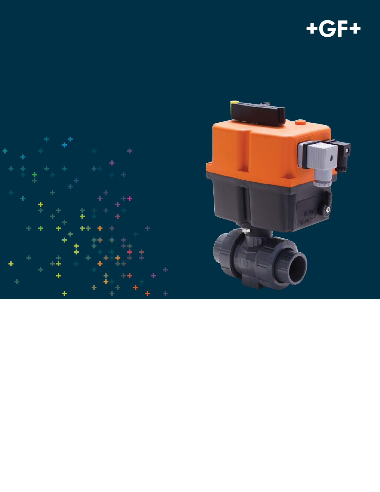
Electrically Actuated Ball Valve
Type 104
General
• Size: ½”–2”
• Material: PVC, CPVC, ABS
• Seat: PTFE
• Seals: EPDM or FPM
• End Connection: Solvent cement socket, threaded
• Actuator Housing: Glass-fi lled PP
• Voltage: 110 VAC, 220 VAC, 24 VDC
• Duty cycle: 75%
• Limit Switches: Two SPST 5A
Optional Features
• Voltage: 12VAC, 12VDC, or 24VAC
• End Connection: Flanged
Key Certifi cations
• NSF 61: PVC and CPVC
Specifi cation
The Type 104 Ball Valve shall be true union and utilize a fl oating ball
design. The actuator shall be single voltage with a manual override.
Two position switches for feedback shall be standard. The ball shall
be fully molded and full port with two way blocking capability. The
stem shall be blowout proof, utilizing a double o-ring seal and a predetermined break point opposite the media side of the stem seals.
The seat carrier shall be adjustable and reverse threaded. The handle shall double as a seat carrier adjustment or removal tool. The
valve nut threads shall be of buttress type. Ball seats shall have an
elastomeric backing o-ring and all elastomeric seals shall be of like
material. ANSI fl anged versions shall meet ANSI B16.5 150lb standards. All valves shall be tested in accordance to ISO9393 and designed to ISO16136 standards. All valves shall be manufactured under ISO9001 for Quality and ISO14001 for Environmental Management.
Following assembly, every valve shall be tested and certifi ed bubble
tight exceeding Class VI standards.
Page 2
Technical Data
EA 04
Nominal torque Mdn 14.8 ft-lb
Peak torque 18.4 ft-lb
Control time 7 seconds/90º ±10% without load
Actuating angle 90°–270°
L/W/H (Actuator only) 7.0"/4.1"/5.2"
Housing materials Polyamide
Position indicator Optical, integrated
Emergency manual override Integrated, standard
Rated voltage +5% 110 VAC, 50/60 Hz
Consumption at peak torque +/- 5% 110 VAC: 0.15 A - 33 W
Duty cycle 75% at 77°F/15 min
Protection class IP 65
Power connector plug 3 P+ E per DIN EN 175301-03
Limit switch connector plug DIN 3337 (mini DIN)
Weight 3.8 Pounds
Limit switches 2 SPDT Micro, 5A 250V
Ambient temperature -4° – 158°F
Important Note: Some residual voltage may be present on the closed terminal when the valve is in the open state and on the open terminal when in the closed
state. For position indication the auxiliary limit switches should be used. The power terminals should not be used for position indication.
220 VAC, 50/60 Hz
24 VDC, 50/60 Hz
220 VAC: 0.15 A - 33 W
24 VDC: 0.55 A - 13.2 W
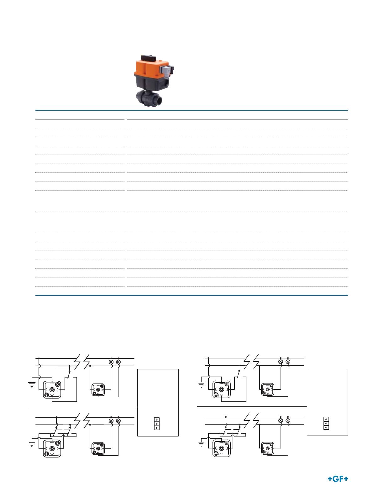
Wiring Diagrams
SCHEMATIC DIAGRAM / ELECTRIC WIRING
N
VAC
L
OPEN
CLOSE
21
3
SCHEMATIC DIAGRAM / ELECTRIC WIRING
-
VDC
+
OPEN
1
2
CLOSE
2
SCHEMATIC DIAGRAM / ELECTRIC WIRING
N
CLOSE
1
3
CLOSE
1
3
OPEN
ACTUATOR
INTERNAL
OPEN
CONFIGURATION
SELECT
JUMPER
AC or DC
IN PCB
AC
DC
R20
2
2
VAC
L
OPEN
CLOSE
1
-
VDC
+
OPEN
1
2
3
SCHEMATIC DIAGRAM / ELECTRIC WIRING
CLOSE
2
CLOSE
1
3
CLOSE
1
3
OPEN
ACTUATOR
INTERNAL
OPEN
CONFIGURATION
SELECT
JUMPER
AC or DC
IN PCB
AC
DC
R20
2
2
Page 3

0
Pressure Temperature Curves
The following graphs are based on a 25 year lifetime water or similar media application
PVC
240
225
210
195
180
165
150
135
120
105
90
Pressure (psi)
75
60
45
30
15
0
20 40 60 80 100 120 140 160
Threaded/Flanged
Socket
Temperature (°F)
ABS
165
150
135
120
105
90
75
60
Pressure (psi)
45
30
15
0
-60 -40 -20 0 20 40 60 80 100 120 140 160
Temperature (°F)
CPVC
240
225
210
195
180
165
150
135
120
105
90
Pressure (psi)
75
60
45
30
15
0
20 40 60 80 100 120 140 160 180
Threaded/Flanged
Temperature (°F)
Socket
Flow
The following information is based on water applications at 68º F
Pressure Loss
10
1
0.1
.01
1 10 100 1000 10000
3/8"
1/2"
3/4"
1"
Flowrate (GPM)
1-1/4"
1-1/2"
2"
2-1/2"
3"
4"
Cv Value
Size (inch) d (mm) Cv (gal/min)
½ 20 12.9
¾ 25 24.5
1 32 49.0
1¼ 40 70.0
1½ 50 112.0
2 63 217.1
3
Page 4

Dimensions
Socket/threaded
Flanged
All materials
All materials
Inch D H H1 H2 H3 L1 L2 L3 L4 M
½ 1.97 6.61 1.06 0.47 5.7 1.9 5.2 2.2 0.98 M6
¾ 2.28 6.8 1.18 0.47 5.7 1.9 5.2 2.2 0.98 M6
1 2.68 6.82 1.42 0.47 5.7 1.9 5.2 2.2 0.98 M6
1¼ 3.31 6.98 1.73 0.59 5.7 1.9 5.2 2.2 1.77 M8
1½ 3.82 7 2.01 0.59 5.7 1.9 5.2 2.2 1.77 M8
2 4.88 7.25 2.52 0.59 5.7 1.9 5.2 2.2 1.77 M8
PVC/CPVC
Socket Threaded Flanged
Inch
½ 4.13 2.4 3.86 2.56 5.87 3.5 2.38 0.5 0.57
¾ 4.76 2.76 4.37 2.92 6.5 3.88 2.75 0.5 0.58
1 5.24 2.99 5 3.23 7.24 4.25 3.13 0.5 0.66
1¼ 6.06 3.54 5.79 3.85 8.11 4.63 3.5 0.5 0.69
1½ 6.46 3.7 6.18 4.33 8.7 5 3.88 0.5 0.76
2 7.2 4.21 7.2 5.31 9.88 6 4.75 0.63 0.82
LzLzLD1D4D5R
ABS
d (mm)
20 3.74 2.52
25 4.33 2.83
32 4.84 3.11
40 5.57 3.7
50 6.18 3.74
63 7.2 4.21
Socket
Lz
GF Piping Systems
Tel. (714) 731-8800, Toll Free (800) 854-4090, Fax (714) 731-6201
us.ps@georgfi scher.com, www.gfpiping.com
#1334-60 (3/15)
© 2015 Georg Fischer LLC
Printed in USA
 Loading...