


6SUNSHINE
User and Installation Guide
6SUNSHINE
User and Installation Guide
READ THIS WARNING BEFORE USING THE GEONAV
WARNING
THE ELECTRONIC CHART IS AN AID TO NAVIGATION
DESIGNED TO FACILITATE THE USE OF AUTHORIZED GOVERNMENT CHARTS, NOT TO REPLACE THEM. ONLY OFFICIAL GOVERNMENT CHARTS AND NOTICES
TO MARINERS CONTAIN ALL INFORMATION NEEDED FOR THE SAFETY OF NAVIGATION AND, AS ALWAYS,
THE CAPTAIN IS RESPONSIBLE FOR THEIR PROPER USE.
The use of the GEONAV implies knowledge and acceptance of this warning by the user.
NOTE: The technical characteristics and functions described in this manual are subject to change as a result of improvements or changes to the product.

Introduction |
4 |
INTRODUCTION
The GEONAV is a chart plotter that displays your boat’s current position with respect to an electronic chart.
The unit can be optionally equipped with a built-in GPS receiver that can track up to 12 satellites simultaneously and be interfaced with:
•An external GPS
•A depth sounder
•An autopilot
By using a GEONAV and a NAVIONICS electronic chart, you will never get lost even in bad weather conditions such as fog, rain or dark because your plotter will always display where you are and where your are heading to.
The ROUTE function will allow you to plan a trip, MARKERS will allow you to mark points of interest whereas the TRACK function will allow you to record your actual route. Thanks to the unlimited capacity of the new CompactFlash™ cartridges - that can also be used on PCs as personal hard disks - the instrument can store a large amount of route, track and marker data.
NAVIONICS GOLD CHARTS are available for all the most popular boating areas and can be used in addition to official paper charts to obtain additional information, such as the availability of port services, as well as tides and currents data. NAVIONICS electronic charts are available worldwide from authorized NAVIONICS dealers.
Should new functions be available in the future, it will be possible to update the GEONAV internal software at any NAVIONICS dealer.
GPS inside model
Characteristics
5
CHARACTERISTICS
General characteristics
•Compact chart plotter with optional built-in GPS receiver and antenna
•12-channel internal GPS (optional)
•Satellite acquisition time: 2 minutes (cold)
15 minutes first fix (with internal GPS)
•GOTO function (Port, Nearest Service, Marker, Lat/Lon)
•External GPS interface via NMEA 0183
•Depth sounder interface via NMEA 0183
•Display of depth and water temperature data (if interfaced with an echosounder)
•Autopilot interface via NMEA 0183
•Chart Rotation (head-up display)
•Screen Amplifier™ function
•Autozoom™ function
•Overzoom™ function
•8 marker shapes, 8-character name
•Reverse route function
•Selectable depth units (meters, feet and fathoms)
•Cartography with port services and Tides and Currents data
•16 zoom levels
•Heading vector
•CompactFlash™ cartridge
•Storage of routes, tracks and markers in separate files on CompactFlash™ cartridges
•Built-in world map
•Splash-proof
•Weight: 1 kg
Electrical characteristics
•Input voltage: 9.8VDC to 18 VDC with protection against reverse polarity and overvoltage
•Power consumption: 10 W
English |
English |
Characteristics |
6 |
|
7 |
•Operating temperature: 0° to +60° C, humidity 93%
•Storage temperature: -20°C to +70°C, humidity 93%
•Color LCD, TFT 5.6”, sunlight visible
•Adjustable backlight and contrast
•Backlight keypad
•Pixel resolution: 240 x 320
•32-bit RISC processor
Memory characteristics
•Up to 20 waypoints per route
•Up to 500 trackpoints
•Up to 99 markers per group
•Number of routes, tracks and markers: unlimited, depending on the size of the CompactFlash™ used
Interface characteristics
•Standard NMEA 0183 sentences
-from the position sensor:
GLL, VTG, GGA, RMC, GSV, ZDA, RMA, GSA
-from the depth sounder: DBT, MTW
-to the autopilot:
APA, APB, XTE, RMB, BWC, GLL, VTG
If received from the GPS, the following sentences are transmitted:
GGA, RMC, ZDA
Accessories
•Bracket for fixed installation
•Gasket and drilling template for panel mounting
•Data cable for connection to external GPS, depth sounder and autopilot
•User’s manual
•Carrying case
English |
English |

Installation and Precautions |
8 |
INSTALLATION AND PRECAUTIONS
To avoid electromagnetic interference, the GEONAV must be positioned at least 0.35 meters away from magnetic compasses or flux-gate sensors, such as those used on autopilots and remote electronic compasses.
The GEONAV is water resistant, but not waterproof. It is essential that the rubber cover on the right side of the unit is firmly inserted into the cartridge slot; the rubber cover should be removed only when the CompactFlash™ has to be inserted or replaced and, in this case, the unit must be perfectly dry.
NOTE: Any damage caused by the presence of water inside the cartridge slot, due to the cover missing or incorrectly replaced, is specifically excluded from the warranty.
Cleaning
It is recommended that you use a non-alcoholic product to clean the glass, since alcoholic products may damage the glass surface or make it opaque.
Installation
The GEONAV allows using either the built-in antenna for outdoor installation or an external GPS antenna for indoor use.
NOTE: At start-up, the plotter will select the internal GPS by default.
•Internal GPS (if available): For the best reception of satellites, mount your unit in an open area to allow the built-in antenna to have the best sky visibility. If the instrument is installed so as to allow full horizon visibility, the best performance will be ensured.
•External GPS: Instead of a built-in antenna, you can use an external GPS. To connect the GEONAV to an external antenna, use the data cable provided with the unit (see the
Connections Section).
9
•Autopilot: To connect the GEONAV to an autopilot, use the data cable provided with the unit (see the Connections Section).
•Depth sounder: To connect the GEONAV to a depth sounder, use the data cable provided with the unit (see the Connections Section).
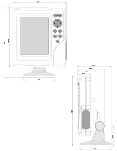
Fixed mounting
The plotter can be mounted on any surface using the mounting bracket provided with the unit (see figure).
Use 4 flat-head screws (5mm) to fix the bracket to the desired mounting surface. Since the bracket does not allow any left or right rotation, make sure that the unit is properly installed for the best view angle.
Panel mounting
Locate the area where the GEONAV is to be installed, then use the drilling template supplied with the plotter to properly cut holes and sockets out of the instrument’s panel.
The neoprene adhesive gasket supplied must be applied to the GEONAV rear side to avoid moisture penetration and to reduce vibrations.
Mounting screws must be 4 mm in diameter and maximum 5 mm in length, plus the thickness of the panel. Do not exceed tightening the screws, in order to avoid damaging the screw seats.
English |
English |

Connections |
|
10 |
|
|
CONNECTIONS |
|
|
Power supply and data cable |
|
||
1. |
Power supply |
|
|
|
red wire |
+VDC |
pin 1 |
|
black wire |
GND |
pin 2 |
2. |
Data input ext. GPS |
|
|
|
brown wire |
ext. GPS in + |
pin 3 |
|
yellow wire |
ext. GPS in - |
pin 4 |
3. |
Data output |
|
|
|
violet wire |
Autopilot out + pin 5 |
|
|
white wire |
Autopilot out - |
pin 6 |
4. |
Data input depth sounder |
|
|
|
blue wire |
DS in + |
pin 7 |
|
green wire |
DS in - |
pin 8 |
|
SHIELD |
|
pin 9 |
If sent by the autopilot, the following NMEA messages are transmitted to external devices: GGA - RMC - ZDA
The GEONAV will add the following messages: APA - APB - XTE - RMB - BWC - GLL - VTG
The data cable is supplied together with the GEONAV plotter.
WARNING: Once the installation is completed, always make sure that all wires are properly connected since wrong connections may damage the unit.
Cartridge Installation
11
CARTRIDGE INSTALLATION
Installing the CompactFlash™
Remove the rubber cap from the cartridge slot located in the right-hand side of the plotter.
Insert the cartridge into the appropriate slot, with the label side (side with a small arrow) backwards and push it.
Replace the cap exercising firm pressure and check that it is perfectly closed, in order to avoid any water infiltration.
NOTE: Make sure of inserting the cartridge correctly. Should you try to insert the wrong side of the cartridge, full insertion into the slot is hampered. Any further attempt to force the cartridge into the slot may damage the cartridge or the plotter. This kind of damage is not covered by the warranty.
Removing the CompactFlash™
Make sure that the plotter is perfectly dry.
Remove the rubber cap from the cartridge slot located in the right-hand side of the plotter, then extract the cartridge.
English |
English |

Cartridge Installation |
12 |
WARNING: The rubber cover should be removed only when inserting or replacing the cartridge.
WARNING: Always use CompactFlash™ cartridges certified by Navionics. The use of non-certified cartridges may result in improper operation of the unit.
The CompactFlash™ cartridges can be used as a mass-storage with any PC computer, so can be the cartridge used by the plotter. However, the plotter needs to find some free space in the cartridge in order to work properly. Prior to use a new cartridge, always make sure that there are at least 2.5MB of free space.
WARNING: Be careful when handling the cartridge files by using the PC. Windows allows deleting and moving files easily, therefore pay attention when using Windows
Explorer not to erase the content of the \NAVIONIC and \GEONAV folders. Damaging the files stored in such directories may result in loss of data or improper operation of the unit.
Keyboard |
13 |
|
KEYBOARD
ZOOM+/ZOOM-
Selects the chart range.
ENTER
Enters a waypoint or a marker, or confirms a selection from the menu.
PAGE
•Navigation mode: Turns navigation data pages.
•Cursor mode:
Allows switching from Cursor mode to Navigation mode.
GOTO
Allows plotting a route toward a manual cursor position, desired marker, port, nearest port service or specified position (lat/ lon).
CLR
•Navigation mode: Deletes the current route.
•Cursor mode: Deletes the last waypoint or the marker pointed by the cursor.
CURSOR
•Moves the manual cursor across the screen.
•Allows switching from Navigation mode to Cursor mode.
•Allows selecting from the options in the menu /submenu.
•At start-up, allows adjusting the screen contrast.
PWR
•Switches the GEONAV on / off.
•Allows adjusting the screen backlight.
•Allows adjusting the screen contrast.
English |
English |

Diagnostic |
14 |
|
|
|
|
DIAGNOSTIC
The GEONAV features a diagnostic program to verify its correct performance, once installed, and to detect problems that may occur during the use of the unit.
To access the diagnostic program, keep pressed any key but CLR, while pressing the PWR key.
The GEONAV will switch on and carry out automatically a test of the whole system; as soon as the memory test is completed, the program will test the LCD, the CompactFlash™ card and the keyboard. Press ENTER to run one test, CLR to skip to the next one. To exit from the keyboard test, press CLR twice.
Once the keyboard test is completed, the diagnostic program allows checking the messages received from the GPS through the NMEA 0183 port. Hold the ENTER key pressed to freeze the messages on the screen, then release it to keep on displaying the new messages sent by the GPS. To test channel 2 (depth sounder or wind instrument), press GOTO. Press CLR to quit.
After the keyboard, the diagnostic program will test the internal GPS (if available) and the backlight. Press ENTER to run one test, CLR to skip to the next one.
Once terminated all tests, press ENTER to re-boot the unit.
WARNING: The internal memory can be cleared by pressing simultaneously the PWR and CLR keys. This operation will delete all the settings stored in the GEONAV and restore factory settings.
NOTE: In case of damaged cartridge or abnormal power spikes, the unit might lock, requiring a power shutdown to restart. In that case, the unit can be turned off without the need of detaching the power, by simply pressing the GOTO, PAGE and CLEAR keys at the same time. This function is useful if the unit is panel mounted or flush mounted and the power switch cannot be easily accessed.
NAVIONICS Electronic Charts |
15 |
|
NAVIONICS ELECTRONIC CHARTS
The GEONAV includes a built-in world map that allows zooming from 4,096 down to 512NM. Additional cartography details relative to a specific area of navigation are available from the CompactFlash™ cartridges storing NAVIONICS GOLD CHARTS.
To display chart boundaries, press PAGE until the menu bar appears, select SETUP, CHART BOUNDARIES, then select ON/OFF to enable/disable the boundaries of the charts stored in the cartridge. A small square will locate the area covered by the cartridge installed.
Increasing/decreasing the chart range
Press the -ZOOM+ key.
Displaying depth and safety contours, geographical names, spot soundings and light sectors
Press PAGE to display the menu, select SETUP and enable the option desired (Depth Cont., Safety Cont., Spot Soundings, Names or Light Sectors) by using the CURSOR key.
Converting depth values into the units set
Press PAGE to display the menu, select SETUP, DEPTH UNITS and then set the unit desired to meters, feet or fathoms.
The GEONAV will convert all the depth values in the unit selected, making them appear like those reported in the official nautical charts (see the figure).
English |
English |
 Loading...