

GEONAV 4C User Manual [fr]
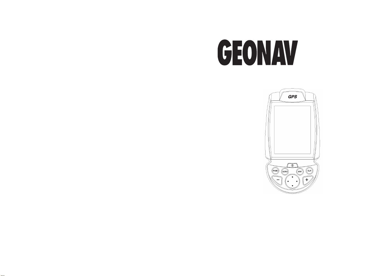
User and Installation Guide
C
4
Manuale d’uso e d’installazione
Manuel d’emploi et d’installation
Bedienungsanleitung und Installationshinweise

4
C
User and Installation Guide

READ THIS WARNING BEFORE USING THE GEONAV
WARNING
THE ELECTRONIC CHART IS AN AID TO NAVIGATION
DESIGNED TO FACILITATE THE USE OF AUTHORIZED
GOVERNMENT CHARTS, NOT TO REPLACE THEM.
ONL Y OFFICIAL GOVERNMENT CHARTS AND NOTICES
TO MARINERS CONTAIN ALL INFORMATION NEEDED
FOR THE SAFETY OF NAVIGATION AND, AS ALWAYS,
THE CAPTAIN IS RESPONSIBLE FOR THEIR PROPER
USE.
The use of the GEONA V implies knowledge and acceptance of this warning by the user.
NOTE: The technical characteristics and functions described in this manual are
subject to change as a result of improvements or changes to the product.

Introduction
4
5
INTRODUCTION
The GEONAV 4C is a handheld chartplotter that displays your
boat’s current position with respect to an electronic chart.
The unit is equipped with a built-in GPS receiver that can
track up to 12 satellites simultaneously and be interfaced with:
• An external GPS
• A depth sounder
• An autopilot
The unit can be installed onboard, interfaced with the NMEA
instruments and - at the same time - work as a portable instrument, thanks to four AA alkaline cells or rechargeable batteries.
The unit is also equipped with a built-in battery charger that
starts operating automatically when the unit is powered. Totally waterproof (IPX7), the unit is equipped with a daylight
visible, color TFT display.
By using a GEONAV 4C and a NAVIONICS Gold electronic
chart, you will never get lost even at night, and in case of bad
weather or reduced visibility because your plotter will always
display where you are and where your are heading for.
The ROUTE function will allow you to plan a trip, MARKERS
will allow you to mark points of interest whereas the TRACK
function will allow you to record your actual route. Thanks to
the unlimited capacity of the new CompactFlash™ cartridges that can also be used on PCs as personal hard disks - the
instrument can store a large amount of route, track and marker
data.
charts to obtain additional information, such as the availability of port services, as well as tides and currents data.
NAVIONICS electronic charts are available worldwide from
authorized NAVIONICS dealers.
NAVIONICS GOLD CHARTS are available for all the most popular boating areas and can be used in addition to official paper
EnglishEnglish

Characteristics
6
7
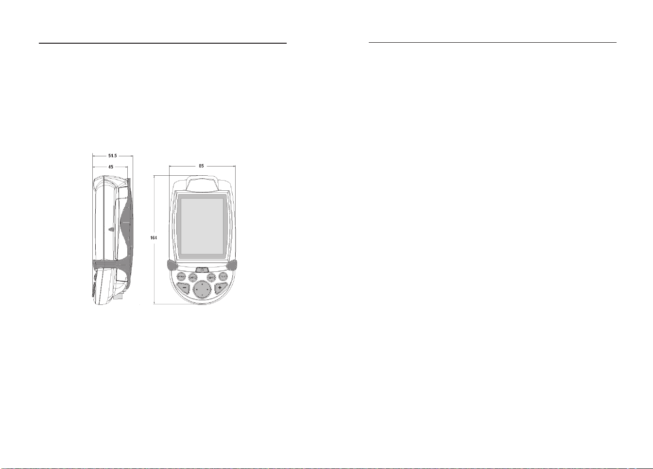
CHARACTERISTICS
General characteristics
• Portable chart plotter with built-in GPS receiver and antenna
• 12-channel internal GPS
• Satellite acquisition time:
2 minutes (cold)
15 minutes first fix
• GOTO function (Port, Nearest Service, Marker, Lat/Lon)
• External GPS or depth sounder interface via NMEA 0183
• Display of depth and water temperature data (if interfaced
with an echosounder)
• Autopilot interface via NMEA 0183
• Chart Rotation (head-up display)
• Screen Amplifier™ function
• Autozoom™ function
• Overzoom™ function
• Easy View™ function
• 8 marker shapes, 8-character name
• Reverse route function
• Selectable depth units (meters, feet and fathoms)
• Cartography with port services and Tides and Currents
data
• 16 zoom levels
• Heading vector
• CompactFlash™ cartridge
• Storage of routes, tracks and markers in separate files on
CompactFlash™ cartridges
• Built-in world map
• Waterproof (IPX7)
• Weight: 450 g., batteries included
• Built-in battery charger (for rechargeable batteries only; see
par. Battery Pack)
• Power consumption: 2.2 W
• Operating temperature: -20° to +70° C, with 12Vdc external power supply. The range is reduced with battery sup-
ply, depending on the type of battery used. Humidity
93%
• Storage temperature: -20°C to +70°C, with 12Vdc external
power supply. The range is reduced with battery sup-
ply, depending on the type of battery used. Humidity
93%
• Color LCD, transflective, TFT 4”, sunlight visible
• Adjustable backlight and contrast
• Backlight keypad
• Pixel resolution: 240 x 320
• ARM9 RISC processor
Memory characteristics
• Up to 20 waypoints per route
• Up to 500 trackpoints
• Up to 99 markers per group
• Number of routes, tracks and markers: unlimited, depending on the size of the CompactFlash™ used
Interface characteristics
• Standard NMEA 0183 sentences
- from the position sensor:
GLL, VTG, GGA, RMC, GSV, ZDA, RMA, GSA
- from the depth sounder:
DBT, MTW
- to the autopilot:
APA, APB, XTE, RMB, BWC, GLL, VTG
Electrical characteristics
• Input voltage: 9.8 VDC to 18 VDC with protection against
reverse polarity and overvoltage
• Battery pack: 4 alkaline or rechargeable batteries (AA)
If received from the GPS, the following sentences are transmitted:
GGA, RMC, ZDA
EnglishEnglish
Characteristics
8
Installation and Precautions
9
Accessories
• Bracket for fixed installation
• Power supply cable with car lighter plug
• User’s manual
INSTALLATION AND PRECAUTIONS
To avoid electromagnetic interference, the GEONAV must be
positioned at least 0.35 meters away from magnetic compasses
or flux-gate sensors, such as those used on autopilots and
remote electronic compasses.
The GEONAV is totally waterproof (IPX7) and weatherproof. It
is essential that the battery pack on the unit’s rear side is
firmly inserted and tightly screwed and that the battery pack
is removed only when the CompactFlash™ or batteries need
replacing. Always make sure that, during the replacement operations, the unit is perfectly dry.
NOTE: Any damage caused by the presence of water inside the unit, due to the lack
or incorrect installation of the battery pack, is specifically excluded from the warranty.
Cleaning
It is recommended that you use a nonalcoholic product to clean
the glass, since alcoholic products may damage the glass surface
or make it opaque.
Installation
The GEONAV allows using either the built-in antenna for outdoor
installation or an external GPS antenna for indoor use.
NOTE: At start-up, the plotter will select the internal GPS by default.
• Internal GPS: For the best reception of satellites, mount your
unit in an open area to allow the built-in antenna to have
the best sky visibility. If the instrument is installed so as
to allow full horizon visibility, the best performance will
be ensured.
• External GPS: Instead of a built-in antenna, you can use an
external GPS. To connect the GEONAV to an external antenna, use the optional NMEA data cable (see the Connec-
tions Section).
EnglishEnglish
Installation and Precautions
10
Connections
11
• Autopilot: To connect the GEONAV to an autopilot, use the
optional NMEA data cable (see the Connections Section).
• Depth sounder: To connect the GEONAV to a depth sounder,
use the optional NMEA data cable (see the Connections Sec-
tion).
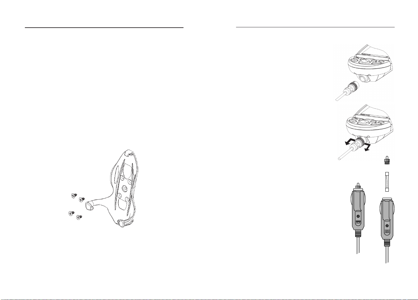
Fixed mounting
The plotter can be mounted on any surface using the mounting bracket provided with the unit (see figure).
Use 4 countersunk head screws (4mm) to fix the bracket to
the desired mounting surface. Since the bracket does not allow any left or right rotation, make sure that the unit is properly installed for the best view angle.
CONNECTIONS
Power supply
The GEONAV can be powered by using the appropriate power supply
cable with car lighter plug or the
built-in battery pack.
Install the power supply cable with
the connector in the position shown
in the figure, then exert a light pressure until clicking.
To remove the cable, extract the ring
nut without rotating it.
When the cable is disconnected, make
sure that the connector is protected
by the appropriate rubber cap.
External power supply
The car lighter adapter has a little
lamp (LED) that goes on if the car is correctly providing power to the bracket.
If the lamp is off:
• check that the 12V voltage is available
from the lighter plug;
• open the adapter and check the fuse.
If the fuse is broken, replace it with a fuse
having the same electrical characteristics.
DO NOT USE ANY BYPASS CIRCUIT.
fuse
LED
The fuse ensures that the special protection circuit inside the plotter works properly in case of accidental short-circuit, polarity inversion and overvoltage.
EnglishEnglish

Connections
12
13
When removing the lighter adapter, connections are the following:
red (or white) +(+12V)
black - (ground)
Battery pack
The battery pack of the GEONAV allows
you to use it as a portable unit. Use 4
alkaline cells or rechargeable batteries,
AA size (if possible, high-capacity batteries, 2000mAh or higher).
Make sure that the unit is off and dry
when replacing the batteries.
To access the battery slot, loosen the locking screws by means of a coin or the round
side of a key, as shown in the figure.
Extract the battery pack, flip it over and
loosen the cover locking screws.
Remove the cover and insert the batteries according to the polarity indicated.
Make sure that the “Battery type” selector located in the cartridge slot is positioned correctly, according to the type
of battery used (“Rechargeable” position,
for rechargeable batteries; “Alkaline” position, for alkaline batteries).
To change the selection, move the small
lever by means of a sharp object.
WARNING: All the units are supplied with the battery
selector set to “Alkaline”. When using alkaline batteries, the selector has to be set to “Alkaline”. You are
warned NEVER to use alkaline-type batteries if the
selector is set to “Rechargeable”. In this case the unit
can be seriously damaged. This kind of damage is not
covered by the warranty. When using rechargeable
batteries, the selector can be set either to
“Rechargeable” or to “Alkaline”. However
the battery charge function is active on condition that the selector is set to “Rechargeable”. The misplacement of the selector may
cause the batteries to break, the corrosive
liquid to leak out and, consequently, the unit
to be damaged. This kind of damage is not
covered by the warranty.
Check that the contacts in the battery
pack are clean and dry.
Before reassembling the battery pack,
make sure that the rubber gasket in the
slot and the rubber O-rings tightening
the locking screws are clean and in the
correct position.
The misplacement of the gaskets, together with any presence
of sand, saline residues or dirt, may be detrimental to the
tightness of the battery slot since it allows moisture to penetrate into the unit and damage the electronic inner components. This kind of damage is not covered by the warranty.
Reassemble the battery pack carrying out the disassembly operations in reverse order.
Should the battery pack not fit, or fit with difficulty in its
seat, check that the CompactFlash™ is correctly inserted.
The partial extraction of the CompactFlash™ blocks the insertion of the battery pack.
The unit can be powered by the batteries only or connected to
an external power supply. When the unit is powered by the
power supply cable, the inner batteries - if they are of rechargeable type - are fully recharged, after which the inner
battery charger is automatically disabled and the batteries disconnected in order to keep their charge.
EnglishEnglish
Connections
14
Cartridge Installation
15
The full charge cycle of a battery set totally discharged requires at least two hours, depending on the battery type and
status.
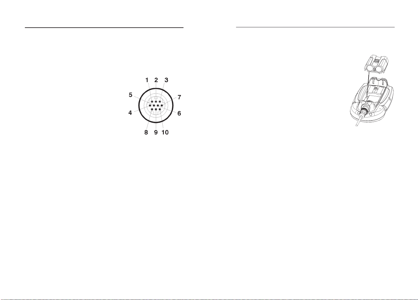
Connections of power supply and data cable
Power supply
1 +VDC
2 GND
Data input ext. GPS
3 ext. GPS in +
4 ext. GPS in -
Data output
5 Autopilot out +
6 Autopilot out -
Audio output
7 Audio out +
8 Audio out -
USB
9 USB D +
10 USB D -
If sent by the autopilot, the following NMEA messages are
transmitted to external devices: GGA - RMC - ZDA
The GEONAV will add the following messages: APA - APB XTE - RMB - BWC - GLL - VTG
The data cable is optional.
WARNING: Once the installation is completed, always make sure that all wires are
properly connected since wrong connections may damage the unit.
USB cable
The GEONAV can be connected to a Personal Computer by
using the optional USB cable. In this case, the unit can use
the internal batteries only, and cannot be powered by the external power.
CARTRIDGE INSTALLATION
Installing the CompactFlash™
Remove the battery pack (see par. “Battery
Pack”).
Insert the cartridge into the appropriate
slot, with the label side (side with a small
arrow) backwards and push it.
Replace the battery pack as described in
the paragraph “Battery Pack” and check
that it is perfectly closed, in order to avoid
any water infiltration.
Removing the CompactFlash™
Make sure that the plotter is switched off and perfectly dry.
Remove the battery pack, then extract the cartridge.
WARNING: Always use CompactFlash™ cartridges certified by Navionics. The
use of non-certified cartridges may result in improper operation of the unit.
The CompactFlash™ cartridges can be used as a mass-storage
with any PC computer, so can be the cartridge used by the
plotter. However, the plotter needs to find some free space in
the cartridge in order to work properly. Prior to use a new
cartridge, always make sure that there are at least 2.5MB of
free space.
WARNING: Be careful when handling the cartridge files by using the PC. Windows
allows deleting and moving files easily, therefore pay attention when using Windows
Explorer not to erase the content of the \NAVIONIC and \GEONAV folders. Damaging
the files stored in such directories may result in loss of data or improper operation of
the unit.
EnglishEnglish
Keyboard
16
Diagnostic
17
KEYBOARD
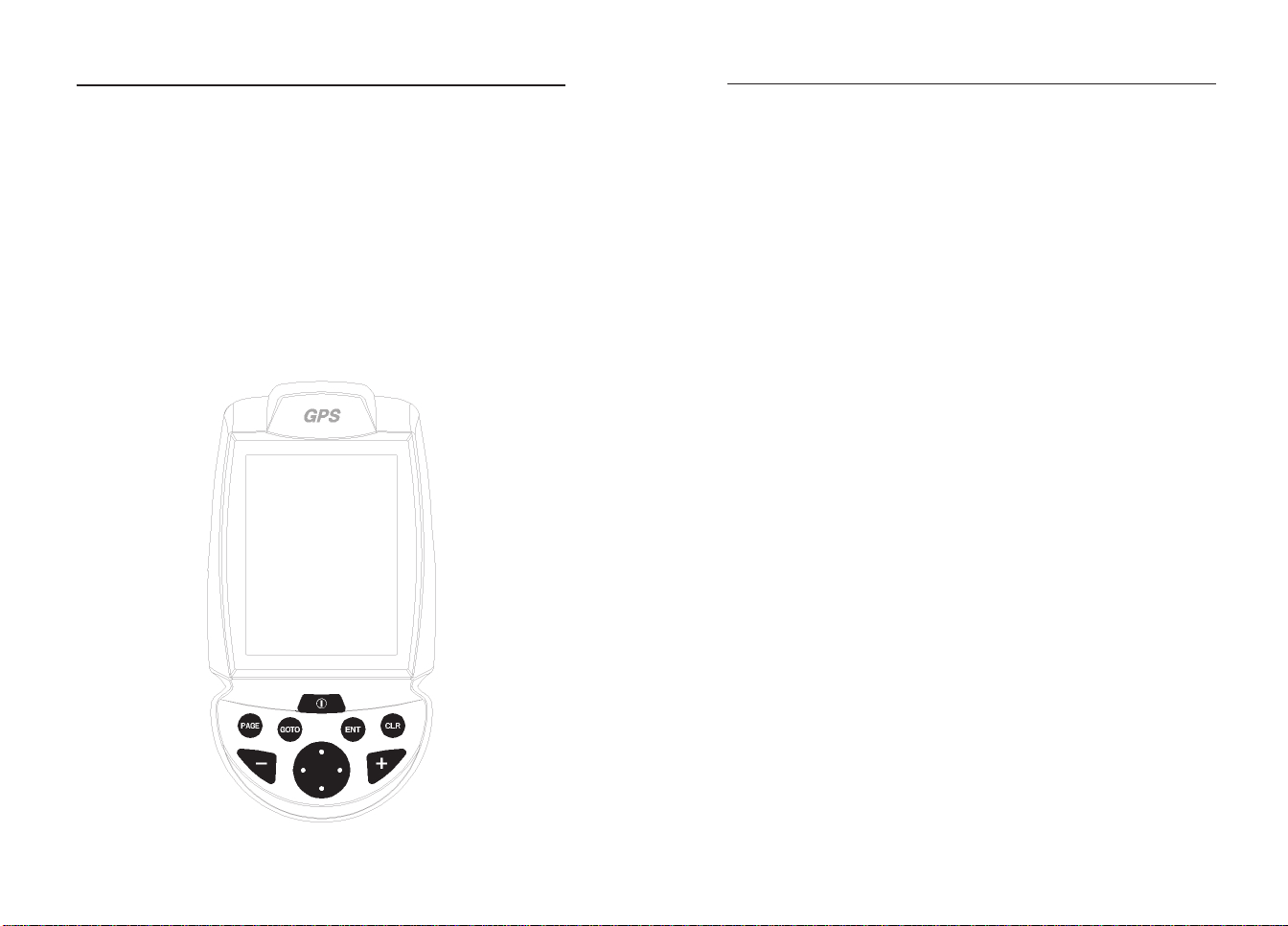
ZOOM+/ZOOM-
Selects the chart range.
ENTER
Enters a waypoint or a
marker, or confirms a selection from the menu.
PAGE
• Navigation mode:
Turns navigation data
pages.
• Cursor mode:
Allows switching from
Cursor mode to Navigation mode.
GOTO
Allows plotting a route toward a manual cursor position, desired marker, port,
nearest port service or
specified position (lat/lon).
CLR
• Navigation mode:
Deletes the current
route.
• Cursor mode:
Deletes the last
waypoint or the marker
pointed by the cursor.
CURSOR
• Moves the manual cursor across the screen.
• Allows switching from
Navigation mode to Cursor mode.
• Allows selecting from
the options in the menu
/submenu.
• At start-up, allows
adjusting the screen contrast.
PWR
• Switches the GEONAV
on / off.
• Allows adjusting the
screen backlight.
• Allows adjusting the
screen contrast.
DIAGNOSTIC
The GEONAV features a diagnostic program to verify its correct performance, once installed, and detect problems that
may occur during the use of the unit.
To access the diagnostic program, hold the ENTER key pressed,
while pressing the PWR key.
The GEONAV will switch on and execute automatically the
diagnostic program. After displaying the system’s software
releases, it will start carrying out the memory test.
As soon as the memory test is completed, the program will
test the NMEA 0183 port, the CompactFlash™, the external
GPS device, the keyboard, the backlight, the LCD and the
audio output. Press ENTER to run each test or CLR to skip to the
next test.
When testing the NMEA 0183 port, hold the ENTER key pressed
to freeze on the screen the messages sent by the GPS device
or the depth sounder, then release it to keep on displaying
any new message.
When testing the keyboard, press CLR twice to exit.
Once terminated all tests, press ENTER to re-boot the unit.
WARNING: The internal memory can be cleared by pressing simultaneously the
PWR and CLR keys while holding the CLR key pressed until the “Erase backup
procedure” message pops up. Press CLR to cancel the operation, or ENTER to
confirm it. This operation will delete all the settings stored in the GEONAV and restore
factory settings.
NOTE: In case of damaged cartridge or abnormal power spikes, the unit might lock,
requiring a power shutdown to restart. In that case, the unit can be turned off without
the need of detaching the power or the batteries, but by simply holding the PWR key
pressed for more than 9 seconds.
EnglishEnglish
NAVIONICS Electronic Charts
18
19
NAVIONICS ELECTRONIC CHARTS
The GEONAV includes a built-in world map that allows zooming from 4,096 down to 512NM. Additional cartography details relative to a specific area of navigation are available from
the CompactFlash™ cartridges storing NAVIONICS GOLD
CHARTS.
To display chart boundaries, press PAGE until the menu bar
appears, select SETUP, CHART BOUNDARIES, then select
ON/OFF to enable/disable the boundaries of the charts stored
in the cartridge. A small square will locate the area covered by
the cartridge installed.
Increasing/decreasing the chart range
Press the -ZOOM+ key.
Displaying depth and safety contours,
geographical names, spot soundings
and light sectors
Press PAGE to display the menu,
select SETUP and enable the
option desired (Depth Cont.,
Safety Cont., Spot Soundings,
Names or Light Sectors) by using the CURSOR key.
Converting depth values into the units
set
Press PAGE to display the menu,
select SETUP, DEPTH UNITS
and then set the unit desired to
meters, feet or fathoms.
Displaying abbreviated navaid characteristics
Position the manual cursor on
the navaid symbol.
A window will show the abbreviated characteristics relative to
the navaid selected.
Description of abbreviated navaid characteristics:
ABBREVIATIONS FOR LIGHT ABBREVIATIONS FOR COLOR
AL alternating AM amber
F fixed B black
FLL fixed and flashing BL blue
FL (...) group flashing G green
FL single flashing OR orange
IQ interrupted quick R red
OC single-occulting VL violet
OC (...) composite group occulting W white
Q continuous group Y yellow
ABBREVIATION FOR PERIOD ABBREVIATION FOR RANGE
..S xx seconds ..M xx nautical miles
Displaying object attributes
Move the manual cursor on top of an object on the chart, then
press GOTO and select INFO. A window will show the description of all the objects present on the chart at the cursor position. Select one object from this window and press ENTER to
show all of the object attributes.
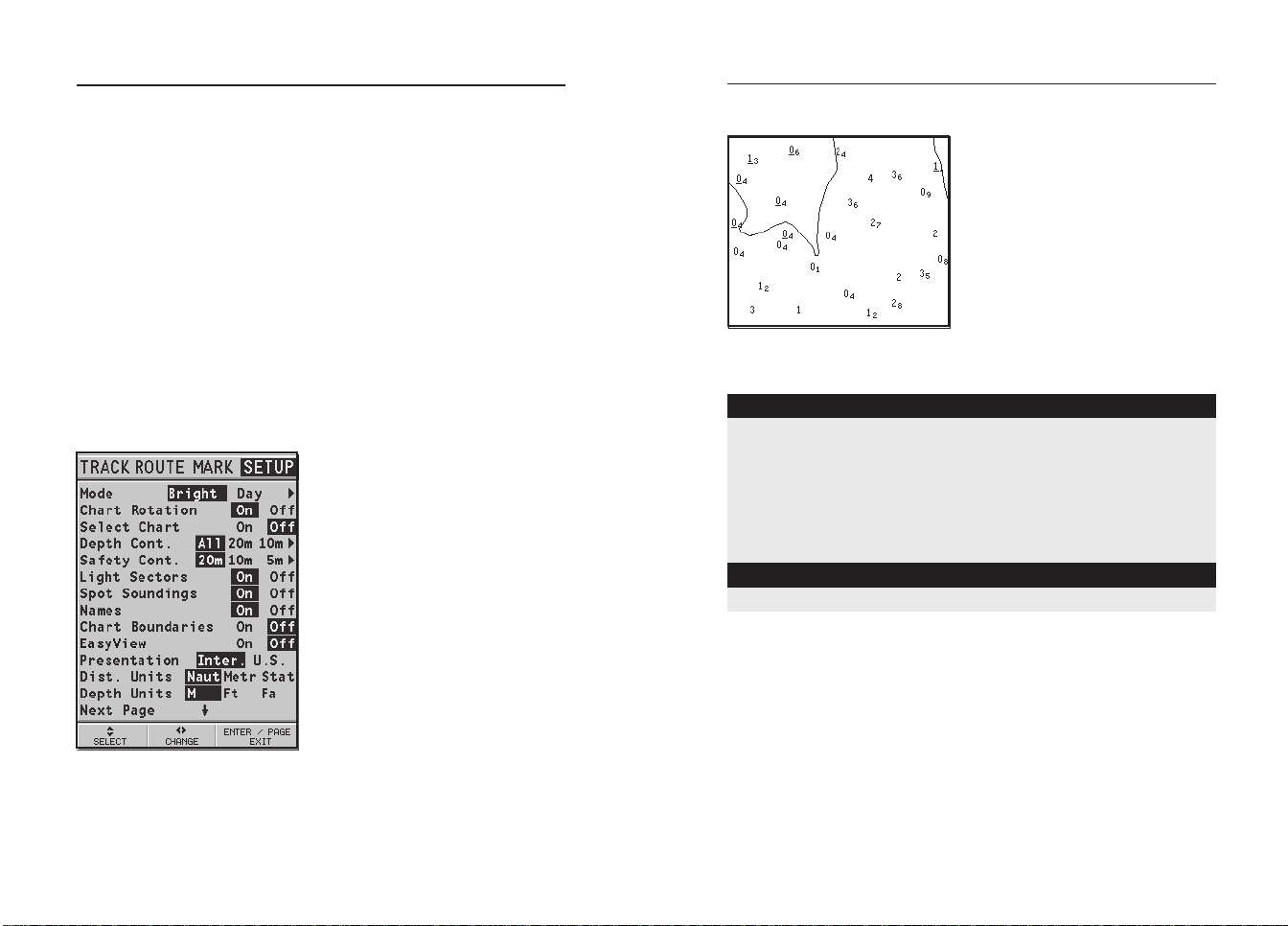
The GEONAV will convert all the depth values in the unit
selected, making them appear like those reported in the official nautical charts (see the figure).
The objects that can be queried include depth contours, depth
areas, point objects (lights, navaids, landmarks, etc.), land
areas, spot soundings, coastlines, rocks, wrecks and in general any symbol present on the chart.
EnglishEnglish
NAVIONICS Electronic Charts
20
21
Changing chart symbols
The symbols used to represent the objects on the chart (buoys,
lights, landmarks, etc.), as well as chart colors, can be selected between paper-chart International or US styles.
Press PAGE to display the menu, select SETUP, then move the
cursor to the next page and select PRESENTATION (INTER. or
US).
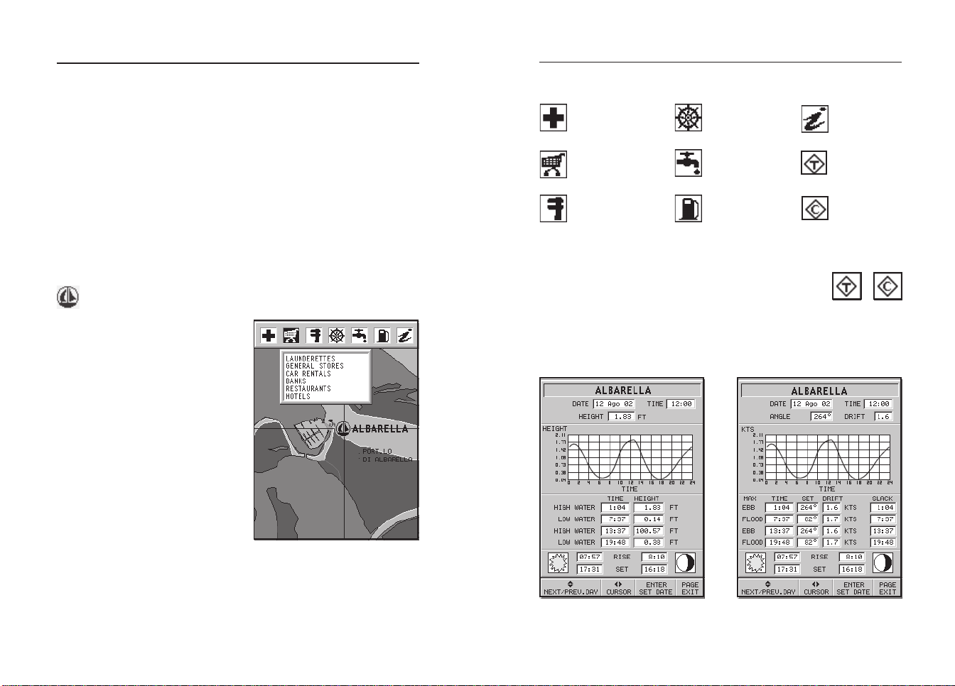
Displaying port services
NOTE: This function is available only with the NAVIONICS cartridges containing the
Port Services feature.
This symbol identifies a port providing services.
Zoom down to 1 NM, position the
manual cursor on the icon (sailing boat) relative to the selected
marina.
By pressing ENTER, a window
will list all the services available
in that port.
Select the desired icon by using
the CURSOR key.
Port services are identified by the
icons shown in the table on the
following page.
Health and first aid
services
T ourist services and
shops
Customer services
Water
Information
and port
authorities
Tide station
Engine, boat,
electronic and
Fuel
Current station
other repairs
Displaying Tides and Currents data
Position the cursor on the icon of a Tide or Current station, then press ENTER.
A graph will show the tide rate or the tidal stream relevant to
the station selected, as measured during the current day.
The number and the type of service available will depend on
the NAVIONICS cartridge installed.
EnglishEnglish
Graphic Items
22
23
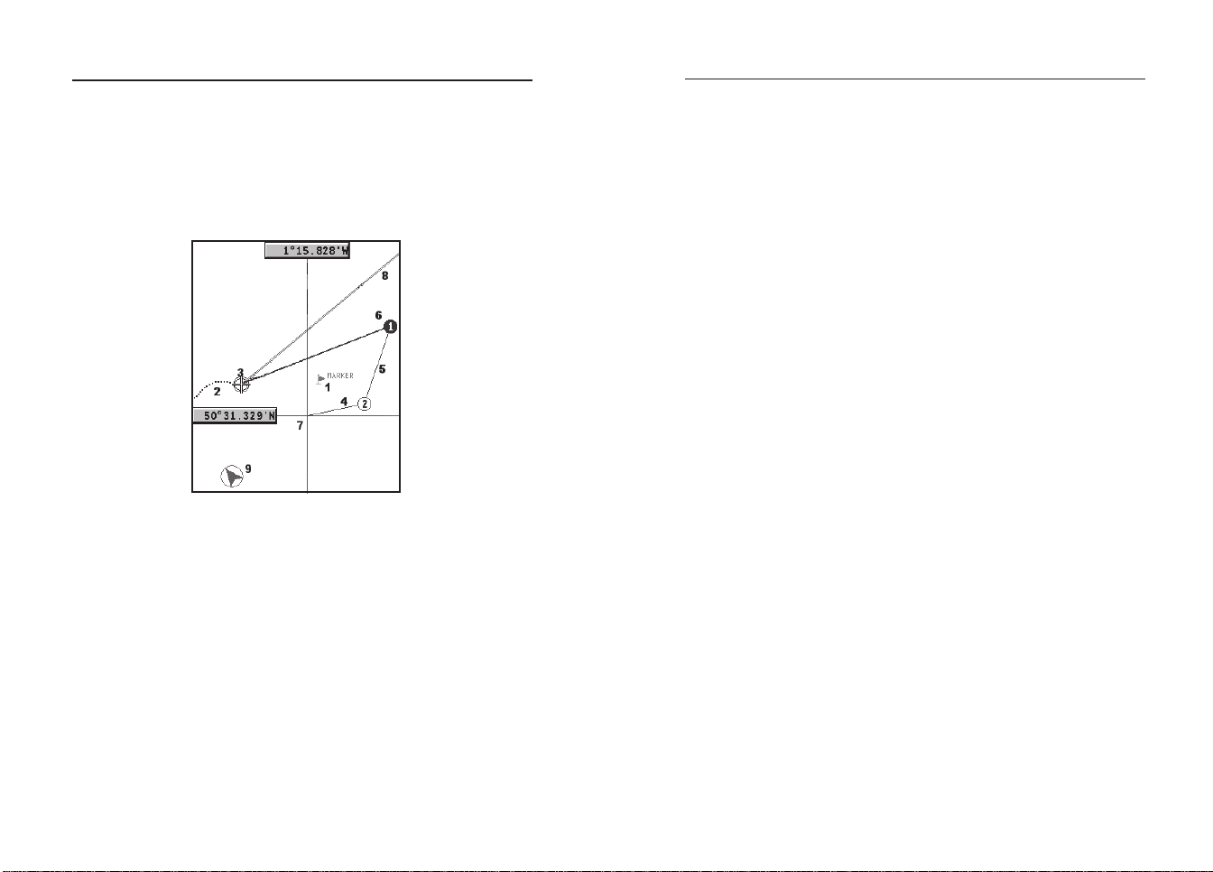
GRAPHIC ITEMS
Besides chart data, the GEONAV displays some graphic items useful during navigation.
The figure below shows some of these items.
1 - Marker
Indicates a point of interest associated with a symbol and a name.
2 - Track segment
Recording of the track actually followed by the boat; the track is
displayed as a dashed line.
3 - Boat’s position
Boat’s position according to the data received from the GPS receiver.
To delete this band, press the PAGE key and switch to Navigation mode.
5 - Route leg
Part of route between two waypoints.
6 - Waypoint
Waypoints are identified by a circle and a number. The route starting point is marked by the “X” symbol. The target waypoint is identified by a filled circle, whereas the route leg currently followed is
identified by a thicker line.
7 - Cursor
Indicates the position expressed in geographical coordinates (latitude and longitude).
It is displayed when the plotter is in Cursor mode.
8 - Heading vector
Indicates graphically the boat’s current route.
9 – North indicator
Indicates the north direction when the Chart Rotation function is enabled.
4 - Rubber band
Line joining the last waypoint entered to the manual cursor, or the
boat’s position to the manual cursor when no waypoint has been
entered.
EnglishEnglish
Functional Characteristics
24
25
FUNCTIONAL CHARACTERISTICS
This chapter describes some of the most important functions
of the GEONAV, as well as the terms most commonly used in
this document.
Switching on/Switching off the unit
To switch the GEONAV on, press the PWR key. To switch it
off, keep the PWR key pressed for more than 1 second.
Internal or external GPS
To make the installation easy, the GEONAV can use either its
own internal GPS receiver or an external receiver, depending
on where the unit is to be installed (indoor or outdoor).
To select the internal/external GPS, press PAGE to display the
menu, select SETUP, then GPS INT or GPS EXT.
Depth sounder
When in depth sounder mode, the GEONAV displays the navigation window in the screen upper part, and, in the bottom part, the
sea depth in graphic form.
The depth value can be expressed in meters (selected by default),
feet and fathoms; press PAGE to display the menu, select SETUP
and then DEPTH UNITS (M/FT/FA).
Navigation mode (Automatic)
The GEONAV enters the Navigation mode as soon as the internal
or external GPS receiver transmits a valid fix; when in Navigation
mode:
• The manual cursor is not displayed
• The depth sounder window can be accessed
This mode is also called automatic because the unit automatically selects the chart scale and updates the boat’s position on
the screen.
Cursor mode (Manual)
When in Cursor mode, the manual cursor is displayed. It is
possible to edit a route, insert or delete markers, display navaid
information etc., but it is not possible to gain access to the
depth sounder window. By pressing one of the four arrows in
the CURSOR key, the unit switches from Navigation to Cursor
mode, and the screen is centered in relation to the manual
cursor. To return to Navigation mode press PAGE.
Chart rotation
Charts are traditionally displayed in
north-up mode. This, however, does not
correspond to reality. For example,
when traveling southwards, the chart
shows, on the right side of the boat,
what is actually located on the left side,
and vice versa.
The Chart Rotation function allows rotating the electronic chart displayed according to the plotted route (COG Course Over Ground) as detected by the
GPS receiver. Since the COG value varies continuously, a filter has been inserted to prevent the chart from bouncing.
To activate the Chart Rotation function,
press PAGE to display the menu, select
SETUP, then CHART ROTATION and
ON. A message will prompt the user to
select the requested maximum range before activating the chart rotation.
The northern direction will be indicated by the symbol .
Autozoom
With the Autozoom function the
GEONAV will always display automati-
Without rotation
With rotation
EnglishEnglish
Functional Characteristics
26
27
cally the boat’s position and the target waypoint at the best
To activate the Autozoom function, press ZOOM+ until the
“AUTOZOOM ? ENTER = YES” message is displayed.
To deactivate the Autozoom function, press the ZOOM key once.
When the GEONAV is turned on, and if at least one waypoint
has been previously entered, the Autozoom function is automatically activated.
Screen Amplifier
This function automatically redraws the chart according to
the boat’s course, to maintain 2/3rds of the screen ahead of
the boat, provided that the boat’s
speed is greater than 3 knots.
This function will be activated
only if no waypoint has been
previously inserted.
Overzoom
The Overzoom function allows
the chart scale to expand anywhere up to 1/4 NM. The
Overzoom does not provide any
additional chart detail, but improves only the readability of the
existing information, thus acting as a magnifying glass.
When the Overzoom is activated,
the unit will warn the user by
available chart range. As the boat
approaches the target waypoint,
the unit will automatically zoom
in. Once the waypoint is passed,
the unit will select the best range
to display the boat’s position and
the following waypoint.
Without screen amplifier
With screen amplifier
replacing RANGE with OVZ (blinking) within the navigation
window.
To activate/deactivate the Overzoom function, press PAGE un-
til the menu bar is displayed, then select SETUP, OVERZOOM
and ON/OFF.
Position calibration
Most position sensors have intrinsic errors that make the boat’s
position incorrect (from few meters to several hundred meters)
with respect to the background display of the chart.
This error is caused by the principle at the root of the satellite-derived position system.
The position calibration allows the user to manually correct
the position error present in all GPS. Press PAGE until the
menu bar is displayed, select SETUP, CALIBRATION and then
ON.
A message will prompt the user to move the cursor to the boat’s
true position by using the CURSOR key. Press ENTER to move
the GPS boat’s position to the point indicated by the cursor.
This operation will save the calibration for use in future calculations.
NOTE: When the calibration is activated, the coordinates will be marked by (*).
To cancel calibration, press PAGE until the menu bar is displayed, select SETUP, CALIBRATION and then OFF.
Local time
By this function the user can enter local time instead of the
Greenwich time (GMT) supplied by the GPS receiver.
To enter local time, press PAGE until the menu bar is displayed, select SETUP, SET TIME and then LOCAL.
A window will allow entering local time by using the CURSOR
key. Press ENTER to confirm the operation.
EnglishEnglish

Functional Characteristics
28
29
To cancel local time, press PAGE until the menu bar is displayed, select SETUP, SET TIME and then GMT.
Chart presentation
This function allows the user to select the symbols and colors
of chart presentation between International mode and US mode.
To change the chart presentation mode, press PAGE to display
the menu, select SETUP, PRESENTATION and then choose
the option desired.
Display mode
The chart color can be selected among three predefined modes:
BRIGHT (bright light), DAY (normal light) and NIGHT (poor
light).
Press PAGE to display the menu, select SETUP, MODE and
then choose the option desired.
Depth contours
This function allows the user to select the display of depth
contours; the options available are:
OFF: no depth contour displayed
5m: display of contours only with depths up to 5 meters
10m: display of contours only with depths up to 10 meters
20m: display of contours only with depths up to 20 meters
ALL: all depth contours are displayed
Safety contours
This function allows the user to display the depth areas corresponding to the safety contour desired. The options available are:
OFF: no depth area displayed
2m : areas with depths up to 2 meters in dark blue
5m : areas with depths up to 2 meters in dark blue, up to 5
meters in blue
10m: areas with depths up to 5 meters in dark blue, up to
10 meters in blue
20m: areas with depths up to 10 meters in dark blue, up to
20 meters in blue
The areas whose depths are over the limit set, and therefore
navigable under safety conditions, will be displayed in white.
Dryline areas are always displayed in green.
NOTE: The mentioned colors are those used in the DAY mode. In NIGHT mode, the
areas with depths over the limit set, and therefore navigable under safety conditions,
are in black, whereas the colors below the limit are dark blue for higher depths and
blue for lower depths (e.g., 5m: areas with depths up to 2m displayed in blue, up to
5m in dark blue).
Chart loading
At start-up, the list of the NAVIONICS electronic charts stored
in the cartridge is shown, provided that a CompactFlash™
cartridge has been inserted.
Select the chart desired by CURSOR, then confirm by ENTER.
Each time the unit is switched on, the latest chart used will
be loaded. To load another chart stored in the CompactFlash™.
press PAGE to display the menu, select SETUP and then SELECT CHART.
Contrast/Brightness
Press the PWR key to display the CONTRAST/LIGHT window. To switch from one option to the other and to adjust the
contrast/brightness level, press CURSOR. Press the PAGE key
to exit.
Easy View mode
The GEONAV allows doubling the visibility of the electronic
chart. Once the Easy View mode has been enabled, the chart
will be magnified.
EnglishEnglish

Functional Characteristics
30
Getting Started
31
Battery management
When the unit is powered by the batteries, a battery-shaped
icon shown in the upper left corner of the screen displays
their charge status. The icon shows when the batteries are
being recharged, provided that the unit is on.
To increase the life of the battery charge, it is possible to set
the automatic switching off of the backlight and screen by
selecting SETUP, and then BATTERY SAVING.
If no unit’s key is pressed during the time interval set, the
backlight and the screen will switch off automatically. As soon
as any key is pressed, the unit will automatically switch on
again.
Keyboard lock
To lock the keyboard, press the “+” and “-” keys simultaneously.
To restore the keyboard operation, press again the “+” and “-”
keys.
GETTING STARTED
We recommend that you use the GEONAV intuitively, since
no damage will be caused by pressing an incorrect button.
Make sure that the unit is powered,
insert a CompactFlash™ cartridge and
then press PWR.
At start-up, the last chart used will be
loaded by default. If the chart is not
found, the list of NAVIONICS charts
stored into the CompactFlash™ cartridge will be displayed. Select the desired chart by the CURSOR key, then
confirm by pressing ENTER.
A message will warn the user that electronic nautical charts
do not replace official government charts.
Press the PWR key to turn the display backlight on and adjust
brightness by the CURSOR key; press PAGE to continue.
The Satellite window will show the configuration of the satellites in use.
As soon as the GPS receiver has obtained a valid fix (it can
take a few minutes), the boat’s position and the relevant area
will be displayed at the best scale available.
The default language is English. To change the language, press
PAGE to display the menu, then select SETUP, LANGUAGE
and the desired language by the CURSOR key.
The line, or vector, starting from the boat indicates the boat’s
direction, to be ignored if the boat is stationary.
The window situated in the lower part of the screen will
display the boat’s speed, route and chart scale.
EnglishEnglish
Getting Started
32
33
The GEONAV is in Navigation
mode; by pressing the CURSOR
key, it is possible to switch to
Cursor mode (editing mode). The
cursor geographical position is
shown by two windows.
To plot a route starting from the
boat’s position, move the cursor
to the position desired, and press
ENTER to insert a waypoint at the
cursor’s position, that will be indicated by a circle containing the
number 1.
The windows will show distance, bearing and the time to
reach the target waypoint.
Press the PAGE key to go back to
Navigation mode.
To add more waypoints, press
CURSOR and repeat the operations
described above.
As new waypoints are added, the
numbering will increase progressively.
In case of error, waypoints can
be deleted by pressing the CLR key
(Cursor mode), starting from the
last entered.
To go back to Navigation mode,
press PAGE.
If an autopilot is connected to the GEONAV, the plotted route
is automatically followed as soon as the Navigation mode is
enabled.
NOTE: The cursor can be moved to the desired position by using the GOTO function
as well. See the GOTO Section for more details.
EnglishEnglish
Operating Modes
34
Satellite Window
35
OPERATING MODES
The GEONAV can operate in two different modes, Cursor and
Navigation, each giving access to different functions.
CURSOR MODE
When the GEONAV is in Cursor mode, the crosshair cursor is
displayed. The CURSOR key allow browsing through the electronic chart, as well as editing or creating the route. See the
Route Section for more details.
To enter the Cursor mode, press the CURSOR key.
NAVIGATION MODE
In Navigation mode, the boat’s position icon replaces the
crosshair cursor and several data windows can be accessed.
To enter the Navigation mode, press the PAGE key repeatedly.
As the fix is valid, the windows sequence is the following:
SATELLITE > NAVIGATION > MENU > DEPTH SOUNDER > TRIP >
LAT/LON > INFO > RUNWAY
The Depth Sounder window is displayed provided that data
is received from a depth sounder.
The Info window is displayed provided that a NAVIONICS
cartridge featuring Tides and Currents data is active (see the
Info Window Section).
SATELLITE WINDOW
NOTE: If a NAVIONICS cartridge with the Tides and Currents feature has been
inserted, the Satellite window will disappear as soon as a valid fix is obtained and be
replaced by the Info window.
At start-up the satellite window
displays how many and which
satellites are tracked by the GPS
receiver.
The outer circle represents the
horizon, the inner one identifies
a 45° elevation with respect to
the horizon, and the central
circle points to the zenith.
The small squares with numbers
show the satellites available. The
numbers of differential satellites,
if any, are displayed from bottom to top.
As soon as the satellite is tracked by the GPS receiver, the
square turns red. The bars displayed on the left identify the
signal quality; the longer the bar, the higher the signal quality.
On the left of each bar, two digits indicate numerically the
signal/noise ratio.
Additional information:
• Day, month, year, local or Greenwich time (at the first
start-up the GEONAV is initialized to Greenwich Time).
• Boat’s position (lat/lon) (or the latest valid fix if the GPS
receiver is still searching for satellites).
• Data on the current satellite situation (number and fix).
EnglishEnglish
Satellite Window
36
Navigation Window
37
• SOG, COG and altitude.
The latitude and longitude values relevant to the boat’s position are displayed as soon as three satellites are tracked and a
2D fix (two dimensions) is available.
The altitude value is available only if four satellites are tracked
and a 3D fix is obtained.
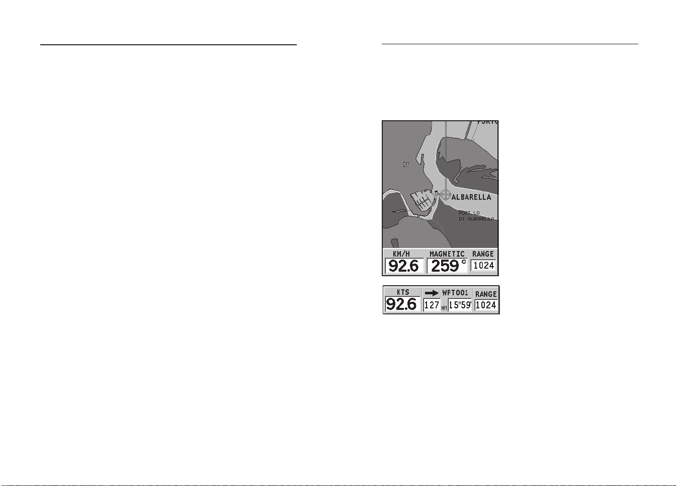
As soon as a valid fix is available, the GEONAV will automatically switch to Navigation mode and display the boat’s position at the best chart range available; the window at the bottom of the screen will indicate the boat’s course and speed.
NAVIGATION WINDOW
This window is activated automatically as soon as the GPS
receiver has obtained the boat’s position (FIX OK).
If no route is present, speed,
course and chart range are displayed at the bottom of the
screen.
By using the ZOOM key, the chart
detail level can be increased,
thus accessing NAVIONICS chart
data.
If a route has been inserted, the
screen will display the following data:
• Boat’s speed
• Distance from the target
waypoint
• Estimated time of arrival at
the target waypoint
• Chart range
EnglishEnglish
Menu
38
Depth Sounder Window
39
MENU
The menu bar, displayed at the top of the screen, allows selecting
from the following options:
TRACK: To activate/deactivate the track function and to save,
recall and delete the track saved.
ROUTE: To delete, reverse, store, recall a route and display
route information.
MARK: To delete, store and recall markers.
SETUP: To activate/deactivate the plotter’s setup.
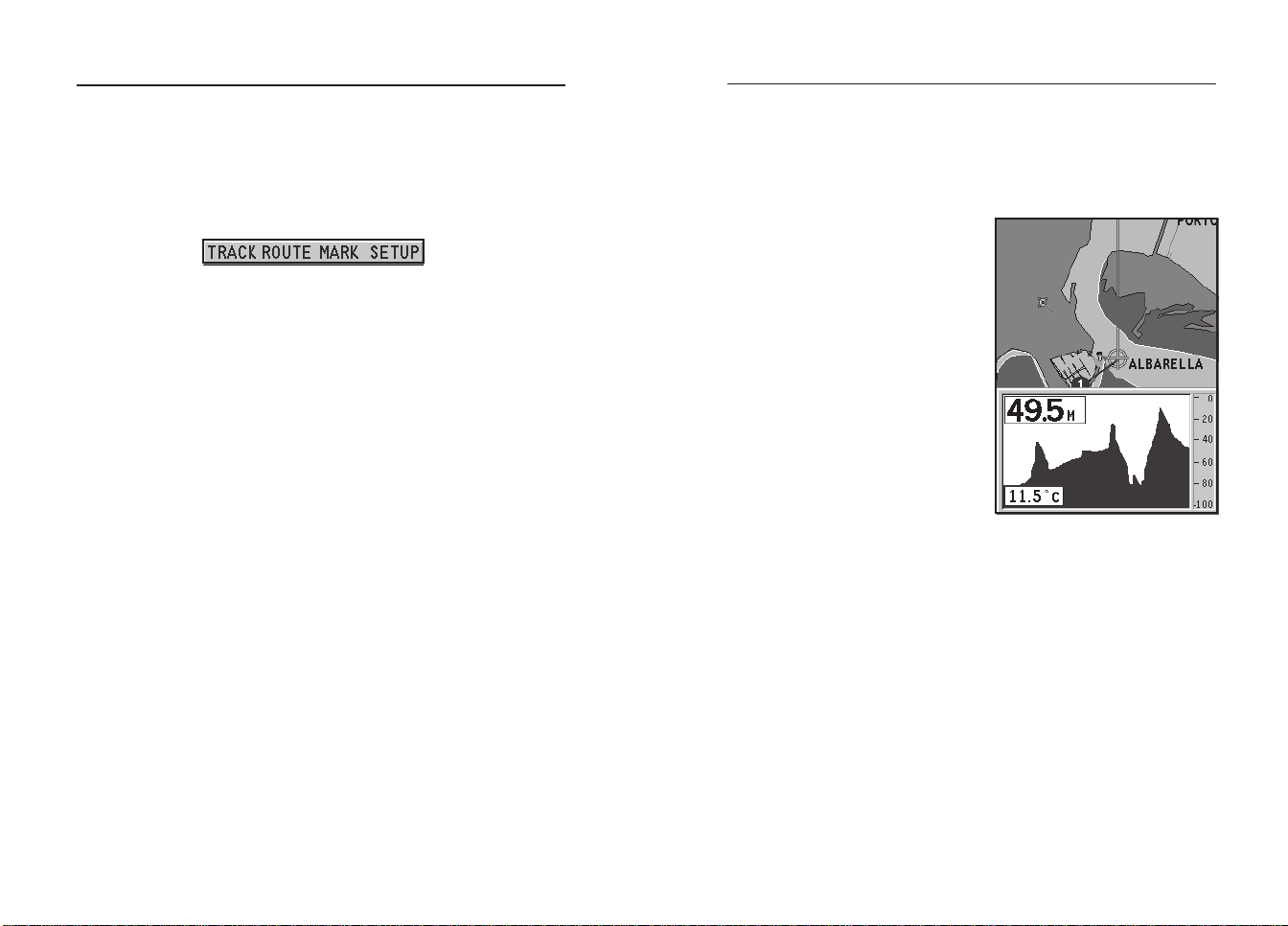
DEPTH SOUNDER WINDOW
A depth sensor can be interfaced with the GEONAV via NMEA.
In this case, the GEONAV auto-
matically enables the depth
sounder function, displaying a
graph of sea depth.
The depth scale, whose unit can
be selected from the menu in
meters, feet or fathoms, will
change automatically to show
deeper or shallower water.
In Navigation mode, press PAGE
until the depth sounder window
appears.
The window will display the following data:
• Water depth
• Depth scale
• Water temperature (if available)
When navigating in waters deeper than sounder access range or if
the boat’s speed is too high for depth sounding, data acquisition
will be interrupted and the number replaced by “—”.
To deactivate the depth sounder window, press PAGE.
EnglishEnglish
Info Window
40
Trip Window
41
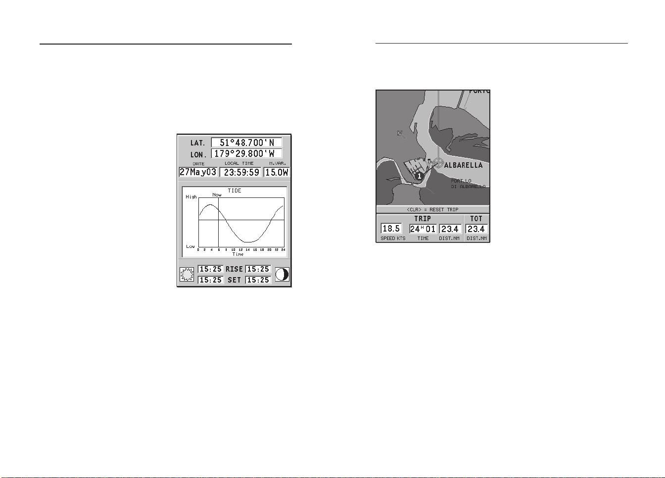
INFO WINDOW
When a NAVIONICS cartridge featuring Tides and Currents
data is present, this window displays further information,
besides the forecast data supplied by selecting the Tides and
Currents station.
The following data is displayed:
• Latitude and longitude at the
current boat’s position
• Current time and date
• Value of magnetic variation
received by the GPS
• Dawn and sunset time
• Moonrise and moonset time
• Moon phase
• Graph of estimated tide level
with respect to the current
position
WARNING: Unlike the graph displayed at a T&C station position (accessible through
the GOTO function, or by positioning the cursor on the Tides and Currents station
symbol) which is as accurate as supplied by hydrographic offices, this graph shows
estimated data, being the result of interpolation between the two Tides and Currents
stations nearest to the point of interest. The accuracy of the estimate may vary,
depending on the coast type, the distance to the nearest stations, and other geographical features.
TRIP WINDOW
The trip window shows the data
relating to the route followed and,
in particular:
• Average speed
• Time elapsed from departure
• Partial distance covered
• Total distance covered
To reset partial counters before
starting a new journey, press CLR.
EnglishEnglish
Runway Window
42
Lat/Lon Window
43
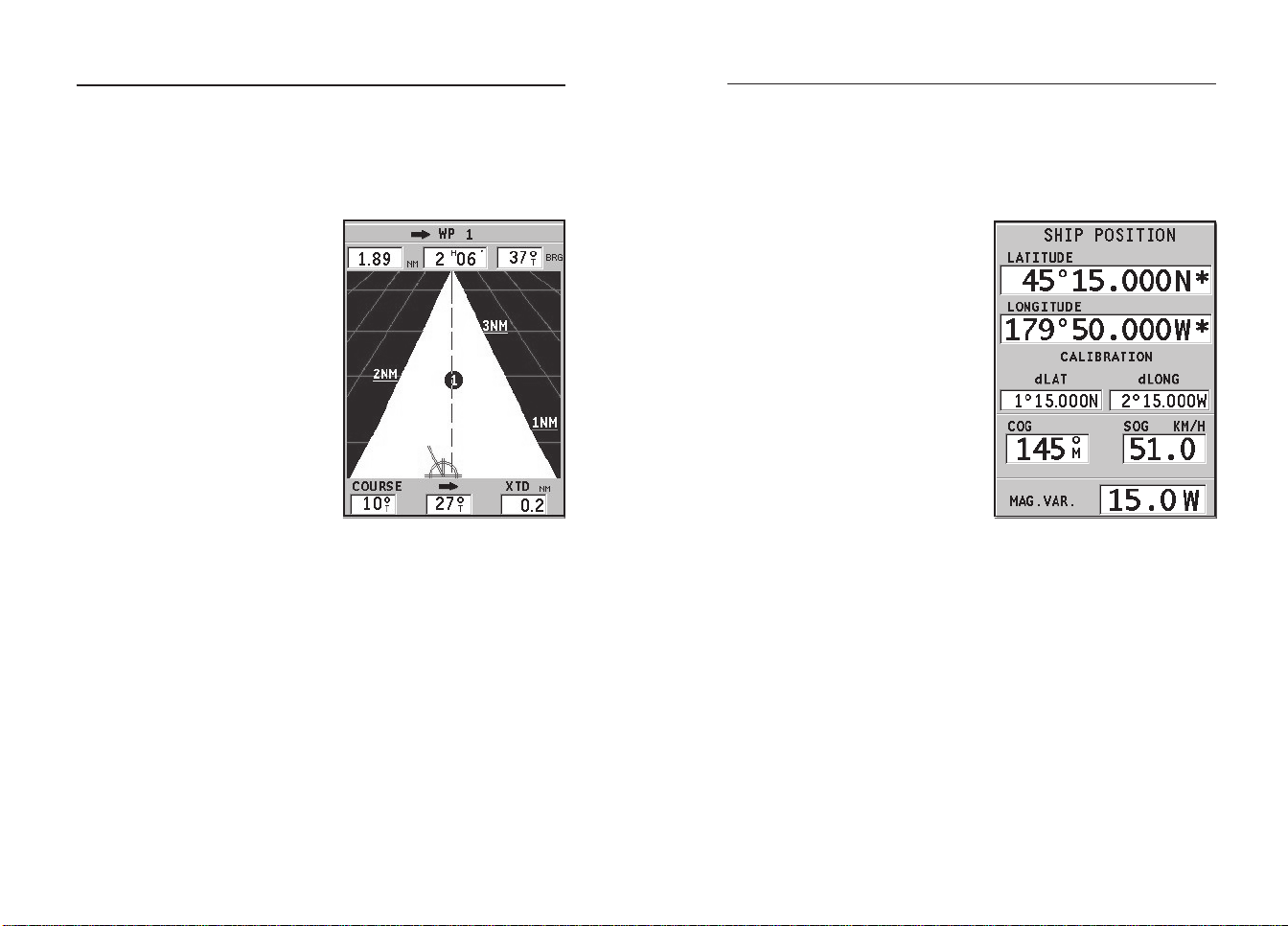
RUNWAY WINDOW
This window displays the following information on the target
waypoint:
• Name of the target waypoint
• Distance from the target
waypoint
• Estimated time of arrival to
the target waypoint
• Bearing
• Course
• Steering angle
• XTD (right/left distance from
the planned route)
The graph shows the boat’s position with respect to the route.
When the XTD goes up to the
limit of 2 NM, the boat symbol
will reach the right or left side
of the runway.
NOTE: This window is available in Navigation mode only.
LAT/LON WINDOW
This window displays the following information on the boat’s
current position:
• Geographical coordinates
(latitude/longitude)
• The position correction applied to the latitude and longitude (option SETUP, CALIBRATION)
• Magnetic variation value received by the GPS
• Course (COG)
• Speed (SOG)
NOTE: This window is available in Navigation mode only.
EnglishEnglish

Route
44
45
ROUTE
EDITING A ROUTE (CURSOR MODE)
Creating a waypoint
Using the CURSOR key, move the cursor on the position desired and press ENTER to insert a waypoint.
To enter further waypoints, move the cursor and press ENTER.
The new waypoint will be appended to the existing route.
Up to 20 waypoints per route can be entered by using the
GOTO function as well (see the GOTO Section).
Deleting the last waypoint
Press CLR. If the last waypoint is out of screen, the “DELETE
WP? ENTER = YES” message will be displayed.
Press ENTER to confirm the deletion.
Deleting a waypoint
Use the CURSOR key to position the cursor on the waypoint to
delete and press CLR.
Deleting all waypoints in a route
Press the CLR key repeatedly until the “NO WP PRESENT”
message is displayed.
Moving a waypoint
Position the cursor exactly on the waypoint to move; press
ENTER to capture the waypoint, then move the waypoint to the
position desired and confirm the operation by pressing ENTER.
it more easily from the other route legs. A window will also
show the leg captured.
Move the manual cursor to the position desired, insert the
new waypoint and confirm by pressing ENTER.
EDITING A ROUTE (NAVIGATION MODE)
If the manual cursor is displayed, press the PAGE key to enter
Navigation mode.
Changing the target waypoint
Use the “Route to a waypoint” function (see the GOTO Section).
WARNING: The route will be modified and the new target waypoint selected will be
the first waypoint in the route.
Deleting all waypoints
Press the CLR key to show the “DELETE ROUTE? ENTER =
YES” message. Press the ENTER key to confirm the deletion or
another key to exit.
FUNCTIONS IN THE ROUTE MENU
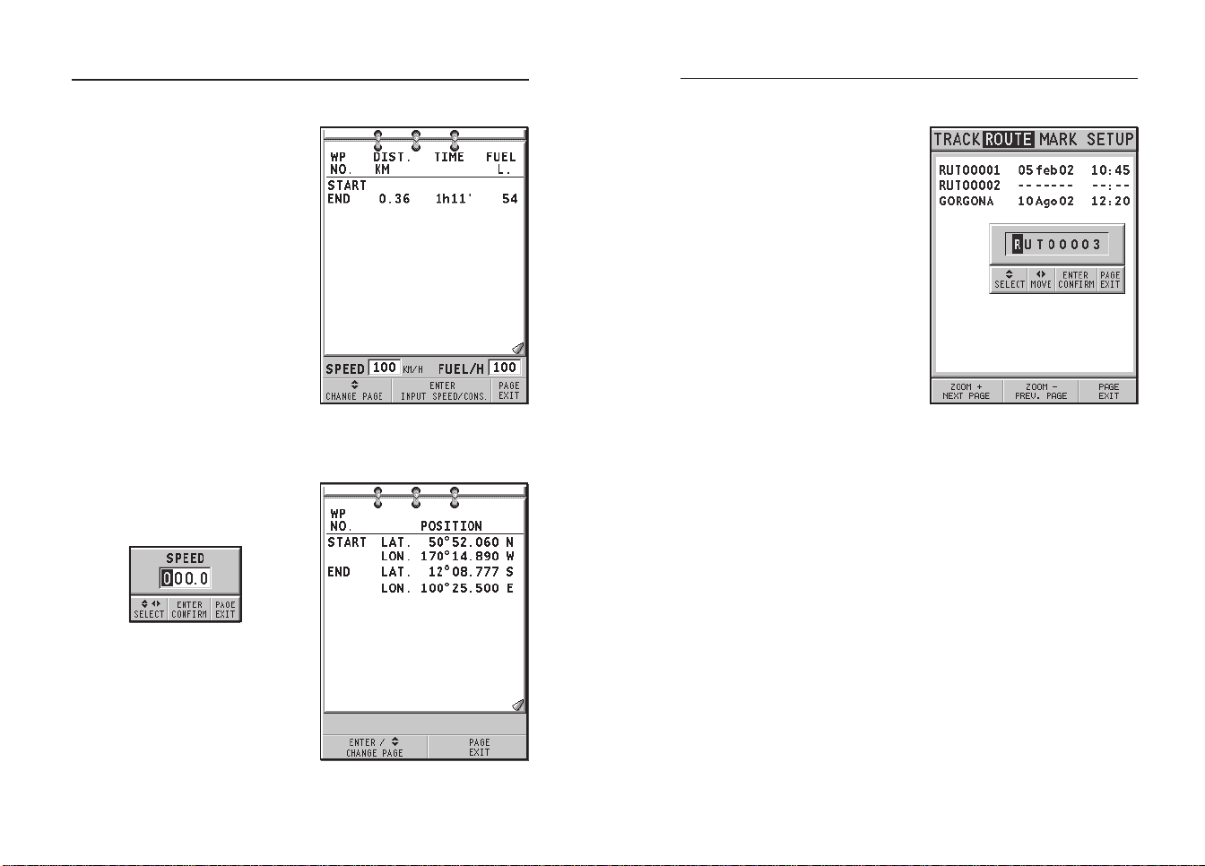
Route Info
Route information is displayed in two pages; the first shows
general route information, whereas the second contains the
geographical coordinates of all waypoints.
Press the PAGE key repeatedly to display the menu bar, select
ROUTE, INFO and then press ENTER.
A window will show the following information:
WP NO.: Waypoint ID
Inserting a new waypoint in a route
Position the cursor exactly on the route leg to edit and press
ENTER to capture the leg.
Once captured, the leg will show a thicker line to distinguish
DISTANCE: Distance from START to current waypoint
TIME: Estimated time from START to current waypoint
FUEL: Estimated fuel consumption (liters)
EnglishEnglish
Route
46
47
The time to arrive to the waypoint
and fuel consumption are displayed provided that estimated
speed and fuel consumption values have been entered (see the
Entering speed and fuel consumption data Section).
To switch to the next page
showing the geographical coordinates of each waypoint, use
the CURSOR key. Go back to the
previous page by using CURSOR
or press the PAGE key to exit.
WP NO.: Waypoint ID
POSITION: Waypoint latitude and longitude
Entering speed and fuel consumption data
This piece of information is used
to calculate the values displayed
in the ROUTE INFO window.
Press the PAGE key to display the
menu, select ROUTE, INFO and
press ENTER.
Enter the data required and confirm by pressing ENTER.
Storing a route in the CompactFlash™
Press the PAGE key to display the
menu, select ROUTE, STORE
and press ENTER. To change the
default name and to confirm the
operation, use the CURSOR key.
The “ROUTE STORED” message
will confirm that the route has
been stored correctly. Once
stored, the route will disappear
from the screen.
Recalling a route from the
CompactFlash™
Press the PAGE key to display the
menu, select ROUTE, RECALL
and press ENTER to open the route catalog; select the route by
the CURSOR key and then press ENTER to confirm, or PAGE to
exit.
The route recalled will be displayed, the Autozoom function
automatically enabled and a window will allow selecting the
target waypoint.
Deleting a route
Press the PAGE key to display the menu, select ROUTE, DELETE and press ENTER to confirm.
The catalog that lists the routes stored in the CompactFlash™
will show the CURRENT item indicating the route currently
displayed. Select the route to delete by the CURSOR key, then
press ENTER to confirm.
By selecting CURRENT, the route currently displayed will be
deleted; the route can also be deleted by pressing the CLR key
while in Navigation mode.
EnglishEnglish

Route
48
Track
49
Reversing a route
Press the PAGE key to display the menu, select ROUTE and
then REVERSE (if no route is currently displayed, the “NO
ROUTE PRESENT” message is displayed).
The waypoint order will be automatically reversed allowing
navigation in the opposite direction. To display information
on the new route, select the ROUTE/INFO option.
TRACK
The Track function allows recording the track actually followed by the boat. The Track function can be enabled and
disabled several times during navigation.
Starting a track
To enable the Track function, press the PAGE key to display
the menu bar, select TRACK, START and press ENTER to confirm. A small circle on the boat’s position will indicate the
track starting point.
Stopping a track
To disable the Track function, press the PAGE key to display
the menu bar, select TRACK, STOP and press ENTER to confirm.
Storing a track in the CompactFlash™
Press the PAGE key to display the menu bar, select TRACK,
STORE and press ENTER to confirm. To change the default file
name and confirm the operation, use the CURSOR key.
The “TRACK STORED” message will confirm that the track
has been stored correctly. Once stored, the track will disappear from the screen.
Each time a track is stored in the CompactFlash™, the plotter’s
memory is cleared and the indicator of memory used in the
TRACK menu is reset to 0%.
Recalling a track from the CompactFlash™
Press the PAGE key to display the menu bar, select TRACK and
then RECALL to open the track catalog.
Select the track desired, then press ENTER to confirm the operation or PAGE to exit.
EnglishEnglish

Track
50
Marker
51
Deleting a track
Press the PAGE key to display the menu, select TRACK, DELETE and press ENTER to confirm.
The catalog that lists the tracks stored in the CompactFlash™
will show the CURRENT item indicating the track currently
displayed.
Select the track to delete by the CURSOR key, then press ENTER
to confirm. By selecting CURRENT, the track currently displayed will be deleted.
MARKER
Markers are used to identify points of interest to which names
and symbols can be assigned.
NOTE: Marker names are displayed starting from the 32 NM chart range.
CURSOR MODE
Inserting a marker
Move the cursor to the position desired
and hold the ENTER key pressed for more
than 2 seconds. A window will display
the symbol and a name automatically assigned to the marker.
Use the CURSOR key to change the marker symbol (8 symbols
available) and name (max. 8 characters) according to the type
of marker to store (e.g., fishing spots, wrecks, rocks, etc.).
Press ENTER to confirm the insertion.
NOTE: The cursor can be moved to the desired position also by using most of the
GOTO functions. See the GOTO Section for further details.
Changing a marker name/symbol
Position the cursor on the marker desired and press ENTER; a
window will display the symbol and the name previously assigned to the marker selected. Use the CURSOR key to change
the marker name and symbol. Press ENTER to confirm the operation.
Deleting a marker
Position the cursor on the marker to delete and press CLR.
NAVIGATION MODE
Inserting a marker
Press the ENTER key to insert a marker at the boat’s position. A
window will display the symbol and the name automatically
EnglishEnglish
Marker
52
Setup
53
assigned to the marker; to change the marker symbol and name
according to the type of marker to store (e.g., fishing spots,
submerged wrecks, rocks, etc.), use the CURSOR key. Press
ENTER to confirm the insertion.
Route to a marker
See the GOTO functions.
MAIN MENU
Storing a set of markers in the CompactFlash™
Press the PAGE key to display the menu, select MARKER, then
STORE and press ENTER. Use the CURSOR key to change the
default name and confirm.
The “MRK. STORED” message will confirm that markers have
been stored correctly. Once stored, markers will disappear
from the screen.
Each time a set of markers is stored in the CompactFlash™,
the plotter memory is cleared and the indicator of the markers
available is reset to the maximum value.
Recalling a set of markers from the CompactFlash™
Press the PAGE key to display the menu, select MARKER and
then RECALL to open the marker catalog.
Use the CURSOR key to select the set desired and confirm, or
press PAGE to exit.
Deleting a set of markers
Press the PAGE key to display the menu, select MARKER, DELETE and press ENTER to confirm.
The catalog that lists the sets of markers stored in the
CompactFlash™ will show the CURRENT item indicating the
set currently displayed.
Use the CURSOR key to select the set of markers to delete and
to confirm. When selecting CURRENT, the set of markers currently displayed will be deleted.
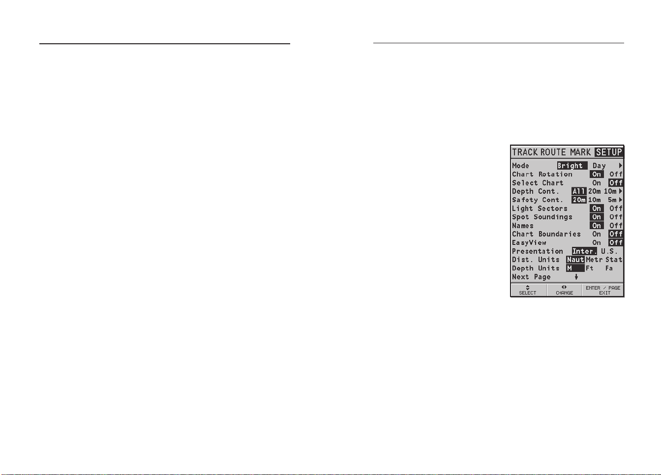
SETUP
The SETUP menu allows setting the available options.
To access the SETUP menu, press PAGE repeatedly to display
the menu, select the SETUP item, then use the CURSOR key to
browse through the options and change the settings.
• Mode (BRIGHT/DAY/NIGHT)
Selects the colors suitable for
the environment.
• Chart Rotation (ON/OFF)
Enables / disables the Chart
Rotation function.
• Select Chart (ON/OFF)
Selects the chart to load from
the CompactFlash™.
• Depth Contours (ALL/5m/
10m/20m/OFF)
Selects the display of depth
contours.
• Safety Contours (OFF/2m/
5m/10m/20m)
Enables the display of the
areas corresponding to the
depth safety contour.
• Light Sectors (ON/OFF)
Enables / disables the display of light sectors.
• Spot Soundings (ON/OFF)
Enables / disables the display of depth point values.
• Names (ON/OFF)
Enables / disables the display of geographical names.
• Chart Boundaries (ON/OFF)
Enables / disables the display of chart boundaries.
• Easy View (ON/OFF)
Enables / disables the Chart Magnification function.
• Presentation (INTER./U.S.)
Selects the symbols and colors of chart presentation.
EnglishEnglish
Setup
54
Goto
55
• Distance Units (NAUT/
METR/STAT)
Selects distance units.
• Depth Units (M/FT/FA)
Selects depth units.
• Set Time (LOCAL/GMT)
Enters local time.
• Calibration (ON/OFF)
Sets the boat’s position received by the GPS.
• GPS (EXT/INT/DIFF)
Selects the built-in GPS, the
external antenna or the builtin GPS with the reception of differential satellites (if available).
• Bearings (TRUE/MAG)
Sets the magnetic mode for all bearings.
• Overzoom (ON/OFF)
Enables / disables the Overzoom function.
• Start USB (ON/OFF)
Enables / disables the connection with the USB port of a
PC (see the USB Connection Section for further information).
• Battery Saving (ON/OFF)
Sets the automatic switching off time for the backlight and
screen, in order to reduce the battery consumption.
• Language (EN/FR/ES/DE/DK/IT/SV/NL/SU/NO/GR)
Selects the language.
GOTO
The GOTO function allows creating a route or changing the
target waypoint in the current route.
Route to a waypoint
Press the GOTO key, select WPT and press ENTER to open the
GOTO Waypoint window. Choose a waypoint, press ENTER to
confirm or PAGE to exit.
As the GEONAV will plot a new route, the waypoint selected
will become the first waypoint in the route, whereas previous
waypoints will be deleted. This function is available in Navigation mode only.
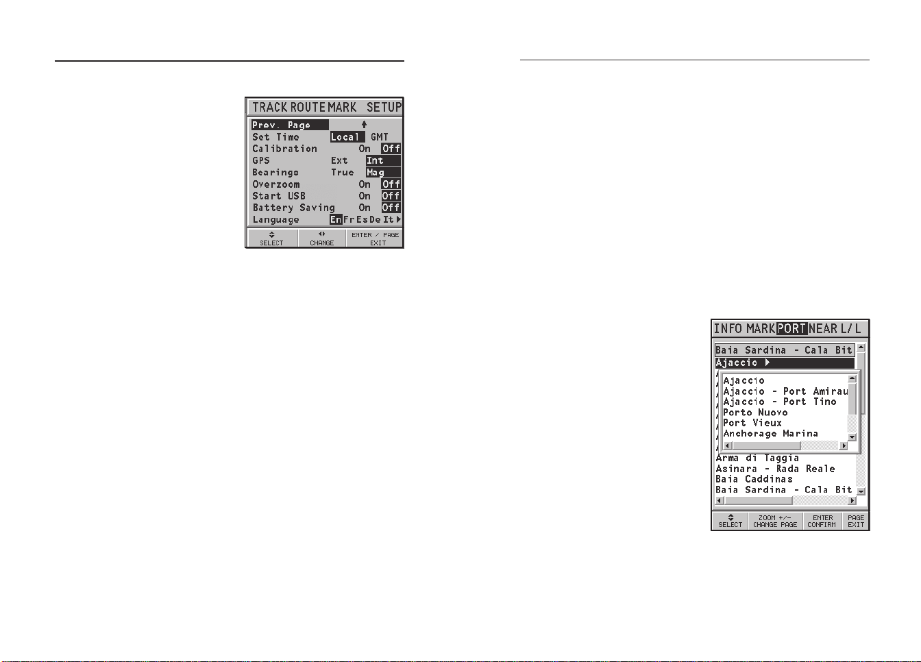
Route to a port
Press GOTO and select PORT by
the CURSOR key. Choose the desired port (the latest 8 ports used
will be highlighted) from the
catalog displayed, then press
ENTER to confirm. To scroll the
list of ports quickly, press ZOOM.
If a port features secondary landing places, its name will show a
small arrow at the end.
By selecting the port name, another window will pop up. By
pressing CURSOR (right), it will
be possible to select the secondary landing place by CURSOR.
To go back to the list of the main
ports, press CURSOR (left), CLR or
PAGE.
Once the desired port has been selected, the GEONAV will
EnglishEnglish

Goto
56
57
insert a waypoint in the port position and append the new leg
to the existing route (if no route is available, the new waypoint
will be connected to the boat’s position).
Press the PAGE key to go back to Navigation mode and enable
automatically the Autozoom function.
Route to a marker
Press GOTO and select MARK by
the CURSOR key. The catalog displayed will list the symbol, the
name and the insertion date/
time of each marker.
By using CURSOR, choose the desired marker (the latest 8 markers used will be highlighted) from
the catalog displayed, then press
ENTER to confirm.
Once the desired marker has
been selected, the GEONAV will
insert a waypoint at the marker
position and append the new leg
to the existing route (if no route
is available, the new waypoint
will be connected to the boat’s
position).
Press the PAGE key to go back to Navigation mode and enable
automatically the Autozoom function.
NOTE: To delete a single marker, select it from the GOTO Marker list and press the
CLR key.
Press GOTO, select NEAR by CURSOR, choose the desired service
and press ENTER to confirm, or
CLR to cancel the operation.
The GEONAV will show the three
destinations closest to the boat’s
position (if in Navigation mode),
or to the cursor’s position (if in
Cursor mode), and position automatically on the closest destination (flashing).
Select one port at a time by using
the CURSOR key; a window will
show the distance and the time
to arrive (estimated on the boat’s
current speed). Press ENTER to
confirm the selection.
The GEONAV will insert a waypoint in the port selected, delete automatically the existing route (if in Navigation mode), or
append the waypoint to the existing route (if in Cursor mode),
then go back to Navigation mode and enable automatically the
Autozoom function.
Route to a point (Lat/Lon)
Press GOTO and select L/L by the CURSOR key. Enter the geographical coordinates desired and confirm by pressing ENTER.
The GEONAV will move the manual cursor to the position
selected; insert a waypoint or a marker.
Tide or current forecast at the nearest survey station
Route to the nearest service
NOTE: This option is available only with the NAVIONICS cartridges containing the
Port Services features. It allows finding and heading for the nearest port featuring the
service desired.
NOTE: This function is available only with the NAVIONICS cartridges containing
Tides and Currents data.
EnglishEnglish
 Loading...